Transcription
Stair lightingcontrollerRGBSTX-1793STX-1793 controller is used for dynamiccolor (RGB) lighting of the stairs. The backlightis switched on with the subsequent steps, depending on the motion directions: ascending ordescending while changing the color of lighting.The controller is adapted to control the RGB LED strips arranged in stair steps and possibly thestaircase handrails.The controller has three programs of color changing: in the first program each stage is lit with adifferent color; in second program color at all steps is the same, but changes smoothly when the stepsare turned on, lights on and off. The last program is fixed and immutable (there can be selected oneof the 7 colors) or will change to another color at every turning on the light of the stairs.When you press the button (eg at the bottom of the stairs), illumination lights up step by stepfrom bottom to top. After lighting up the entire staircase the light is stable for a short period, and thenlighting of the staircase goes from the lower to the upper level, sequentially step by step.Depending on the setting parameters of the controller, the light of the stairs can fade out to zeroor to a minimum value (allowing to illuminate the stairs for better presentation, or climb them easily inthe dark - without turning on a full light - especially important for children!). When you press the topbutton, the stairs are lighted from top to bottom and turned off also in the same direction.In case when another person steps on the stairs, the controller switches on full illumination ofstairs and extinguish them after a set period of time.Lights can be turned on by pressing directly button on the wall, connected to the controller orby the use of additional sensor (infrared, motion, pressure, etc.) to detect when the person stepson the stairs.The controller can support up to 20 steps. It can also control lighting of handrail (max. 2).Number of supported points of light (usually it is the amount of stairs) and the number ofilluminated handrails, are set at the factory and cannot be changed by the user.Other parameters of the controller can be set by the user. These are mainly: time intervals between lightening succesive stairs steps, or time after which steps will be faded out. Additionally, therecan be set up ways of colour change, their brightness and other detailed settings of the controller.1www.stairslight.com
SpecificationsMaximum number of illuminated stairs — 20Quantity of illuminated handrails — 2Voltage — 12VDimensions: length — 14cm (5,5’’), width — 9cm (3,5’’), height — 7 cm (2,75’’)Mounting on T-35 rail — the width of 8 modules.Output capacity — up to 5ARunning — by shorting the input to ground (negative power supply)The number of steps and number of handrails supported by the controller is set at thefactory — when ordering, please give the following information:Stairs backlight type (LED strips or LED lights)Quantity of illuminated handrails (1 or 2),Type of motion sensor (230V or 12V, please link to the sensor to be ordered).If you have problems determining the amount and type of light points or sensors, please contact us.InstallationDriver Installation should be done by the person having advanced skills in the field of electricalengineering, preferably a specialist with permission. Connecting the controller must be strictly carriedout with the power off!AC driver and LEDs should be stabilized with adequate current capacity dependent on theamount and length of the used LED strips or 12V LED light. Do not use a power supply (type12) from halogens — the controller will be damaged immediately! The controller is designed fora voltage of 12V DC (stabilized). Maximum current per output is 5A. Do not exceed this value.The first step is to connect the lights to the driver and press button TOP on the case of controller.The controller should start lighting up the steps one by one. If there is no effect or steps are lightingup in a different way, you should check again carefully how to connect LED lighting.Then it is recommended to adjust the sensor response to the movement without connecting themto the controller inputs. Be sure to first set the sensor pulse time (TIME) to extreme minimum and itshould not be changed during adjustment, and the sensitivity (range) also at the minimum - but thisparameter can be adjusted. In some sensors, there should be disabled or properly adjusted supportfunction (called triggering). Only after obtaining the proper operation of the sensors, they can beconnected to the controller.After connecting the sensor, if only the first step is lighted, or the entire staircase is lighted, thismeans that the sensor pulse time exceeds 20 seconds, or is short-circuited. The sensor should beimmediately disconnected from the controller and replaced operating properly.Only after obtaining the proper light animation, you can begin to connect the motion sensor. Besure to pre-set the operating time of sensors for extreme minimum and sensitivity (range) also atthe minimum value. With some sensors, there should be disabled or switched triggering function.The last step is time intervals adjustment. The best way is to do it after a few days of using thestairs in order to determine as accurately as possible the necessary changes. We recommend youto not adjust the parameters for no particular reason.2www.stairslight.com
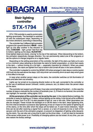
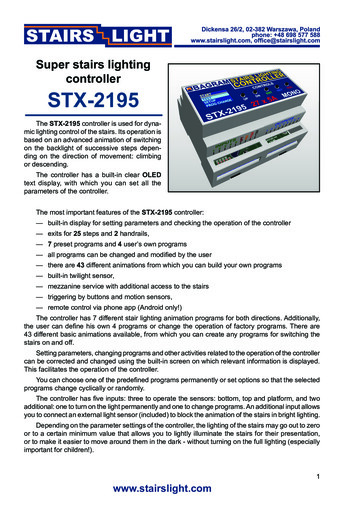
LED LightingSTX-1793 może sterować podświetleniem zrealizowanym wyłącznie za pomocą taśm LED RGB.Taśmy LED na ogół montowane są pod stopniem, a podświetlenie poręczy w pochwycie (świecą wdół). Podłączenie elementów oświetlających do sterownika pokazują kolejne rysunki.Diagram: LED RGB strip connected to the controllerNOTE: Arrangement of points R, G i B on the stripmay vary from shown above!The diagram above shows the connection of the controller to the staircase consisting of 20 stepsand two handrails. Output 1 is connected to the plus ( ) RGB strip from the first, the bottom stepof the stairs, output 2 to the plus ( ) RGB another (higher) step of the stairs, etc. The output 20 isconnected to the plus ( ) RGB strip at last step of the stairs. The output 21 is connected, lookingfrom the bottom of the stairs, to the right handrail (running up), and the output 22 to the left handrail(running down) . Points R, G and B LED strip should be connected properly to each other, ie, all thepoints of R together, all the points of G together and all points B together. Then just set up collectionpoints should be connected to the respective outputs RGB controller.If the staircase is smaller and there is no illuminated handrails, for example you can use exit No.20 for ceiling lighting above the stairs (of course, if you have one). However, there must be used LEDelements with 12V power. Do not connect the lighting powered from 230V!3www.stairslight.com
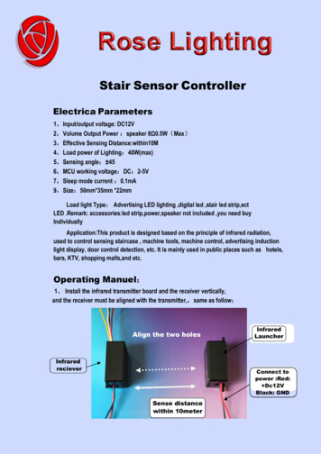
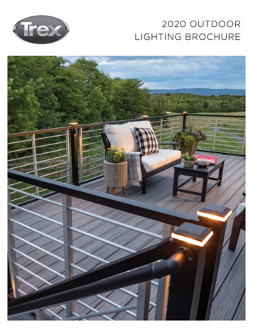
The next picture shows a solution where the exit No. 20 is connected to three 12V LED lightsplaced on the ceiling above the stairs. The driver will be turning it on with the first step and turn off afterabout 2 seconds from the extinction of the last step. Of course, you can use any other light sourcewith the voltage of 12V, depending on the design of the stairs, in place of ceiling lamps.Diagram: Ceiling lightingWhen designing the connections between the controller and LED points, please include yourcurrent flowing in the circuit and select the appropriate type of wiring. Plus supply line for 12V LEDstrips or LED lights should have a much larger cross-section than the cables between the controllerand the LED strips.ATTENTION! You cannot connect the AC to 5V plus ( ) and minus (-) outputs. These contacts are used for low-voltage power sensors.Installation must be carried out very carefully and securely to avoid loosening of wires or shortcircuits between them. LED strip wires should be soldered. We do not recommend using specialsockets and plugs, because after a while, due to the movements of the stairs, they are loose andmay lose contact.4www.stairslight.com
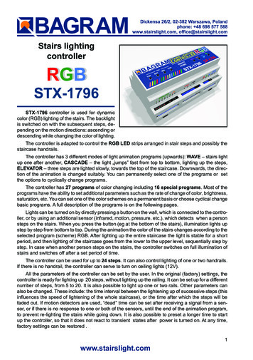
ControlDriver inputs are working on a short to ground. Connecting random mechanical button (notswitch) will run the controller after a short press. One end of the button should be connected to thecontroller input, and the other to ground (minus of 12V). All previous diagrams show this solution.You can also run the driver with other elements or devices, including motion sensors. Motionsensors are found in two versions: the 230V voltage and the voltage of 5 or 12V. Do not connect thesensor directly to the input of the driver, because, especially in the case of 230V sensors, it will cause(at best) incorrect working of the controller, and at worst it can be completely damaged.Before mounting the sensors, please set their parameters. The most important is the length ofthe impulse (time of starting the sensor), which should be set to a minimum and should not exceed15 seconds (preferably about 1-5 seconds — this should be checked before purchase). The secondparameter possible to set on the sensor is its sensitivity and range. This parameter should be setexperimentally in order to enable steady and in the right time.In some sensors you can choose from various modes of operation. Please turn off triggeringmode, because in this mode, the sensor provides the impulse continuously when a person is withinits range - and the impulse becomes too long as for the requirements of the controller.Sensors operating at 230V network require the use of transmitters to separate the 230V circuitfrom the controller inputs. LV Sensors will almost certainly need a special adapter matching thesensor signal to requirements of the controller. The following diagrams and descriptions explain howto connect the most common types of sensors. If you need to use a different type of sensor, pleasecontact the manufacturer to agree on how to connect the sensor.Motion sensors with a voltage of 230 VMotion sensor for 110-230V - CRN 5491A typical motion sensor (230V)is a standard size module and isconnected to the installation box.It has regulatory elements (time,sensitivity, etc.) and usually threecontacts for wires. Two are pluggedinto a 230V network, and the thirdwire is used to power the receiver(the lamp) and is marked with anappropriate symbol. Before installing the sensor, carefully read theinstructions.Some motion sensors have a built-in additional twilight sensor. Depending on the sensitivitysettings it can be inactive in strong light. Thus, illumination of the stairs does not turn on during theday. However, this may cause problems - if it rains, the twilight sensor will lighten the stairs. By adjusting the sensitivity, you can try to prevent this. We can recommend our 230V sensor CRN-5491,modified to work with our controller:.The next diagram is one of a typical motion sensor (230V) connected to the controller. Relaysmust be used! Relay coil voltage must be set at 230V, because this voltage is supplied from themotion sensor. Connect input 1 or 2 and (-) of 12V to the contacts of the relay NO (normally open)and CO (common),. We recommend the assembly to be done very carefully. If the connections aremade erroneously, the controller will be damaged.5www.stairslight.com
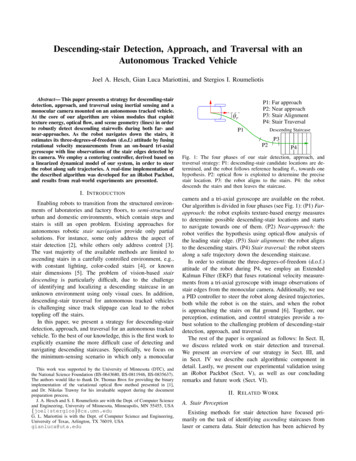
Installation diagram: 110-230V motion sensors connected to the controllerThe relays used to separate 230V circuit fromthe controller may be of any type. We recommendthe relays to be mounted on T-35 bus, the same asthe controller. Their use helps with the installation.Photo to the left shows our product STP-4811 — aset of two relays in a single-rail case T-35. This setmakes it possible to separate 230 V voltage comingsimultaneously from two motion sensors.Set of two relays STP-4811The picture on the next page shows an example of the assembly of motion sensors operating at230V. There are used two one-connection transmitters with stands for mounting on T-35 bus. Due tothe fact that every manufacturer of transmitters and sockets uses a different pin configuration, youshould always carefully consider how to connect the sensor and the controller to the transmitter sothat the driver does not connect directly to 230V!6www.stairslight.com
Installation diagram: motion sensor CRN-5891 connected to the controllerNOTE: Knob “Time” in the sensors must be set to minimum!7www.stairslight.com
Motion sensors for voltage 12VYou can also use miniature motion sensors operating at low supply voltage such as 12V. We offerthe sensor with the symbol CRN-5481. Voltage of the sensor is identical to the LED supply voltage,which greatly simplifies installation of the entire system.Sensor dimensions: plate: 32.5 x 23.5 mm, thediameter of the bowl: 23mm. The sensor has anadjustable impulse length and sensitivity.The sensor can be connected directly to thecontroller input. It is important that the sensor, theadapter and the driver have been combined in theright way, according to the following pictures anddiagrams.Miniature motion sensorOn the back of the sensor is a connector for connecting wires leading to the controller. To facilitateassembly, to each sensor is added the connector tosoldering wires. You should keep the correct orderof wires according to the description on the sensorconnector.The view of the sensor back sideIt is recommended to use colored cables withthe smallest possible diameter, eg. telephone cablebundles. Please note that any mistake in wiring, especially power can damage the sensor or controller.Sensor socket and plug8www.stairslight.com
The diagram below shows exactly the whole set made using 12V motion sensors.Before mounting the sensors, please set their time of action and sensitivity to a minimum. In thecase of sensors with a jumper used to select the operating mode with or without triggering, choosethe position “non-repeatable trigger.”These prepared two sets of adapters with sensors should be mounted in appropriate place onthe side of the first and the last step.Setting the motion sensorsThis is one of the most difficult operations — it requires patience and accuracy. First of all, adjustthe sensitivity of the sensor in order to accurate respond to the person entering the stairs. The secondproblem to solve is that the sensor does not respond to the person descending the stairs - that it notre-activate the fading of the stairs. Best thing to do is to cover the sensor hemisphere respectively. Ofcourse, the arrangement of the sensors is also very important — usually they are placed on the rightside of the stairs looking in the direction of movement (when the right-hand ‘traffic’). Some sensorshave additional adjustable parameter - the so-called ‘dead time’. It is a time measured after pulse forwhich the sensor does not respond to the next person entering into the field of its operations. Patientchanging mentioned parameters will adjust quite well the sensors so that their work and lighting thestairs will be rewarding.9www.stairslight.com
Adjusting the controllerSetting the parameters should be performed only when strictly necessary, after carefully readingthe following description. In case of failure or disturbance of the controller parameters, it can be resetto default settings by the RESET button.To start the parameter setting mode, press and hold the SETUP button on case of the controllerfor about 5 seconds until the LED go off. Release the button to go to the controller parameter settingmode. A few seconds flickering of the green LED corresponds to each parameter. You can set orchange 13 parameters, and therefore there will be twelve consecutive flashes of the green LEDdivided into three groups. Each group, to facilitate, is signalized by different stairs color. To select aspecific parameter to be changed, you should count each flickering and the at relevant number ofthe flickering, press the SETUP button. If you do not want to change a parameter, skip the flickeringwithout pressing the button. If at the parameter setting mode the bottom button is not pressed, noneof the parameters will change.Adjusting controller parameters diagramThe principle of setting the parameters is as follows: setting each parameter is indicated by rapidblinking of the first step of staircase. If during this flickering the bottom button is pressed and held,then, depending on the parameter, you will see from one to dozens of slow flashes. Setting the parameter is to release the button with the desired number of flashes or just after the end of flickering.During the flickering, if the bottom button is not pressed, after a short time of fading out the step,there will appear flickering of the next parameter and so on until the end of setting mode. If desiredflickering is omitted, then the corresponding parameter is not changed. This allows you to set, forexample, only one parameter, except of all the others. Notice: if the button is pressed during theflickering and released immediately after it, but before the first impulse, the value of the parameterwill be set to the factory setting.We recommend setting only one parameter a time.Setting single parameterTo start serring parameters, press and hold the SET button on the driver’s case, until the LEDplaced next will go off. After releasing the buttin, the process of setting parameters will start. It willbe indicated by succesive LED flickering.10www.stairslight.com
Description of parametersThe green color of the stairs - basic parameters1. Program selection. The controller has three color changing programs: in the first one, eachstep is lighted with different color; in the next one, the color of all of the steps is the same,but changes smoothly when the steps are lit; in the last one the color is fixed and immutable(can be selected from 7 colors) or will change periodically to another each time the stairs areilluminated. For the program 1 there are no additional options. For the program 2, you canchange the brightness of the LED and the rate of colors change. In program 3, you can selecta specific color of light or set a cyclic operation (in each stairs illumination the color of lightwill change). Releasing the button after the first pulse enables program 1, after the secondprogram 2, and after the third - program 3.2. Interval between lighting succesive steps. This is the time interval between lighting the steps,which has an impact on the speed of lighting up the whole staircase. The factory setting is0.5 seconds - 10 pulses. To shorten it, the button should be released eg. after 5 pulses; toincrease - for example, after 20 pulses.3. Time between illumination and fading out the steps. This is the time, in which after lightingup the steps one by one, all of the steps lit continuously (before they start fading out one byone). Factory setting is 10 seconds, which equates to 20 pulses.4. The time the whole stairs are lit, when the second (or any subsequent) person will come tothem. It os re-measured at each entry of the new person, and therefore light will turn off aftera set time measured from the last person entry. Factory setting is 20 seconds which equatesto 80 pulses.5. Controller blockade time. If the sensor detects when a person sends more than one pulse forexample, by the movement of other people on the stairs, the driver can react by turning thelights all over the stairs, just like during the entrance of another person. To avoid this, you canset the so-called blockade time counted from the start of the first pulse, during which the driverwill not respond to further impulses. Blockade time is pre-set for 3 seconds, which correspondsto 3 pulses (1 pulse 1 second).The red color of the stairs — color parameters6. Number of colors displayed by the program no. 3. Factory set is maximum 7 colors (see below).This amount can be reduced or increaset - from 1 to 20. This is useful when the user wants todefine his own colors and the driver with program no. 3 to switch between more than 7 colors.Number of colors is set by releasing the button after certain number of pulses. Releasing thebutton immediately after flickering restores factory setting - 7 colors.7. Setting the stairs color for program 3. There is a choice of 7 colors (in order): white - 1, red- 2, green - 3, blue - 4, yellow - 5, cyan - 6, violet - 7. If the cycle operating was not set, thestairs and (if necessary) handrails will be highlighted with consistently chosen color. To selecta specific color, the number of assigned pulses should be measured. Releasing the buttonimmediately after flickering sets the cycle operating - with every each start of stairs lighting,different (next) color will be shown.8. Adjusting brightness for program 2. Range from 1 to 7, where 1 is the darkest color and 7 isfull brightness. Please, select desired number of pulses.9. The rate of color change for program 2. Range from 1 to 7, where 1 is the fastest color changing,and 7 - the slowest. The default setting is 4 - average value. Please select desired number ofpulses.11www.stairslight.com
The blue color of the stairs — additional parametersEach color is composed of three primary colors: red, green and blue - RGB. So it is with thebacklight. It can be set with each color independently in the range from 0 to 250, where 0means complete blanking of color, 1 - a minimum value, and 250 - a maximum value. By setting these values of three colors you can get any color and backlight brightness. At values 0,0 and 0, the light will be switched off. The values 1, 1 and 1 - minimal illumination with whitecolor - and this is the default setting. It can be changed by selecting the desired number ofpulses for each of the colors.10. The brightness of the red color backlight, in range from 0 to 250. Zero can be adjusted byreleasing the SETUP button immediately after the end of flickering.11. The brightness of the green color backlight, in range from 0 to 250. Zero can be adjusted byreleasing the SETUP button immediately after the end of flickering.12. The brightness of the blue color backlight, in range from 0 to 250. Zero can be adjusted byreleasing the SETUP button immediately after the end of flickering.Purple color of the stairs - Settings of Solid ColorsFor the program 3 there are programmed seven solid colors (see point 6). You can changeand set your own color in the RGB code. To facilitate entering each value (0 to 255 ) for eachcolor, you sequentially set a value of hundreds of (0 to 2), dozens (0 to 9) and units (0 to 9).When a value is omitted (the button during the flickering was not pressed) or dissolved soonafter the end of flickering - the value will be set to 0.13. Selecting color number to be programmed. You can select any number (from 1) of the rangeset in step 5. If you won’t press the button while flickering, the program will end parametersetting and proceed to wait for a signal that starts the animation. Each parameter changeoperation allows you to set only one selected color. Therefore, to change few colors you willhave to repeat the process few times. You choose the color number by releasing the buttonafter a specified number of pulses. The following steps set the RGB values for the three primarycolors.Red color (R) - the red color of the stairs14. Setting hundreds. Release the button at 1 (100) or the second pulse (200).15. Setting dozens. Release the button when the number of pulses is equal to the number ofdozens in the red color value, for example after five pulses for 5 dozens (50).16. Setting units. Release the button when the number of pulses is equal to the number of unitsin the red color value, for example after five pulses for 5 units (5).Green color (G) - the green color of the stairs17. Setting hundreds. Release the button at 1 (100) or the second pulse (200).18. Setting dozens. Release the button when the number of pulses is equal to the number ofdozens in the green color value, for example after six pulses for 6 dozens (60).19. Setting units. Release the button when the number of pulses is equal to the number of unitsin the green color value, for example after three pulses for 3 units (3).12www.stairslight.com
Blue color (B) - the blue color of the stairs20. Setting hundreds. Release the button at 1 (100) or the second pulse (200).21. Setting dozens. Release the button when the number of pulses is equal to the number ofdozens in the blue color value, for example after eight pulses for 8 dozens (80).22. Setting units. Release the button when the number of pulses is equal to the number of unitsin the blue color value, for example after four pulses for 4 units (4).Setting three basic colors ends the process of changing one color, the program will finishsetting the parameters and proceed to wait for a signal that starts the animation or anotherparaeter change.Parameters resetIf the user incorrectly changed the parameters and it had an impact on the controller operation,you can easily restore the factory settings of the parameters. Use the RESET button on thetop of the controller. As it is recessed into the case, to press it use a proper stick, for examplea match.To reset the controller, press and hold the RESET button. After a while, the LED will flash.The button must be pressed continuously during all the flashing time. After the LED stops toflash and turns off, you can release the button. Reset is confirmed by three short flashes ofthe LED.At this point, the parameters are reset to their default settings and the controller will worknormally in standby mode, waiting for a signal from the button or sensor.13www.stairslight.com
Stair lighting controller RGB STX-1793 STX-1793 controller is used for dynamic color (RGB) lighting of the stairs. The backlight is switched on with the subsequent steps, de-pending on the motion directions: ascending or descending while changing the color of lighting.