Transcription
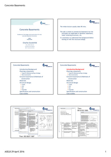
Concrete BasementsThe whole lecture usually takes 90 mins.Concrete BasementsGuidance on the design and construction of in‐situconcrete basement structuresASELB29 April 2016The talk is aimed at commercial basements but theprinciples are applicable to domestic basements,water retaining structures, etc.It is necessary to understand the background beforekicking on with the structural design.Charles GoodchildCEng., MCIOB, MIStructEPrincipal Structural EngineerMPA ‐ The Concrete CentreConcrete BasementsIntroduction/backgroundPlanning a basementConcrete BasementsIntroduction/backgroundPlanning a basement Types & Waterproofing strategy Site ConstraintsGround movements & Methods ofconstructionMaterialsStructural design Types & Waterproofing strategy Site ConstraintsGround movements & Methods ofconstructionMaterialsStructural designLoadsULSSLSExampleSpecification and constructionCase studies LoadsULSSLSExampleSpecification and constructionCase studiesThen:BS 8102:1990BS8102BasementsThen: BS 8007:1987ASELB 29 April 20161
Concrete BasementsThen: CIRIA 139/140 1995What’s new(ish) in basements(and water retaining structures)? Then:Design & Construction of Deep Basements: 2004EN1992-3EurocodesWithdrawal of BS 8110, BS 8007 etcRevision to BS 8102New information: CIRIA C660CIRIA C580 ICE Reducing the Risk of Leaking Substructure: AClients’ Guideuide Debate S Alexander, TSE Dec 06B Hughes, TSE Aug 08? ICE project 0706 on reinforcement to controlcracking (report Feb 2010)CIRIA C660ASELB 29 April 2016BS81022
Concrete BasementsBasement Information CentreConcrete BasementsIntroduction/backgroundPlanning a basement Types & Waterproofing strategy Site ConstraintsGround movements & Methods ofconstructionMaterialsStructural design LoadsULSSLSExampleSpecification and constructionCase studiesWantsClients want:short construction timeslow costslow risk and uncertaintyArchitects want:Dry walls and base – with no impact on space planningSimple shapes – unless it’s shapes they are definingLarge holes – often at points of maximum in-plane stressNo columns – but if you put any in, they will clad them to twice the sizeNarrow beams between holes (not appreciating they will act more like props)Contractors want:Bottom up Construction – simplerCantilever walls – no props, simplerNo tanking – simpler, & anyway it always leaks somewhereNo constraint on construction sequence - leaves more options openConcrete BasementsBasement design requires: an holisticapproachSpace Planning an understandingof both the groundand the structuralbehaviour formalconsideration tructureCost and riskArchitectureGeotechnicsWaterproofing communication:Concrete BasementsOutline of the design process1. Establish Clients requirements2. Site surveys, etc3. Outline designs, methodology and proposals4. On approval do detailed design5. Constructionwhen things get out of sequence. He will assert that HIS sequenceCANNOT have any affect on the design forces Get him on-side ASAP - he can be an allyAnd Engineers?. . . . . . . . . . a simple life!ASELB 29 April 20163
Concrete BasementsPlanning a basementPlanning a basementGradesGradesBS 8102:2009BS 8102:2009 Table 2 provides guidance:Grade of useGrade 1Some leakage, some damp.Parking, Plant roomsGrade 2No water penetration or damp patches.Plant rooms, workshopsGrade 3 Dry environment. Ventilation required.Residential, Commercial(Grade 4) (totally dry and vapour proof)Archives, stores . go to BS 5454As an aid . .Planning a basementTypesPlanning a basementBS 8102:2009Types of water‐resisting construction vs risk BS 8102:2009 :Type ABarrier protectionType BStructurally integralprotectionType CDrained protectionCombinations possiblePlanning a basementPlanning a basementForms of rc basement construction related to site conditionsand use of basement space:CostOther subjects Surveys and ground investigationsWater LevelForm ofMethod of constructionconstructionLow:generally belowfloor levelRC boxIn open excavation or withintemporary worksContiguouspiling Tolerance of buildings to damageMedium to high:permanentlyabove lowestfloor levelSecant pilingBasement excavated after pilingwith the floors acting as props inthe final condition with/withoutsubsequent concrete facingBasement excavated after diaphragm with the floors acting asprops in the final condition Fire safety considerationsincreasingASELB 29 April 2016or sheet piling etcDiaphragmwalling Precautions near underground tunnels, sewers & servicemains Working adjacent to existing structures: Party walls Space planning Integrating basement with the superstructure Client approval4
Concrete BasementsPlanning a basementPlanning a basementExploratory worksParty Walls/Adjacent buildings - noticesNEEDED EARLY - commission early!desk study geological maps, borehole records, ordnance survey, water courses, utilities.site surveys boundaries, adjoining buildings and roads,liaison with adjacent owners, party walls, incoming services, tunnelssubsoil investigation bearing capacity, water level, pile design,earth pressures, settlements, (modulus ofsubgrade reaction) contaminants. See BS EN1997-2 money well spent!assess 3m and 6m notices risk of risk of flooding (EA), likely obstructions,foundation details of adjoining buildings,disposal of groundwater Distortions cause damage – not absolute movement 10 mm often used as a triggerPlanning a basementPlanning a basementSpace planning:Space requirementsCheck for: room for temporary works- clearances for piling rigs.diaphragm wall equipment takes up considerable space. restrictions imposed by owners of underground tunnelsand utility companies dimensions of guide walls for contiguous piles (may bearound pile diameter 800 mm);, wall thicknesses : zone for cavity drains if relevant;, tolerances for piling and temporary works; capping beams projecting features of adjoining structures. superstructure – follow through into basement, Fire – means of escape, compartmentation, accessPlanning a basementPlanning a basementPile tolerancesCapping beamsGuide wall?ASELB 29 April 20165
Concrete BasementsGround movementsConcrete BasementsVertical loadIntroduction/backgroundPlanning a basement& relief Types & Waterproofing strategy Site ConstraintsGround movements & Methods ofconstructionMaterialsStructural design LoadsULSSLSExampleHorizontalload reliefSpecification and constructionCase studiesGround movementsConstruction SequenceBigBenPortcullis House:Observed vertical andhorizontal movementsaround the Palace ofWestminster car park The temporary loads from the construction sequence willprobably have an impact on the permanent design. For anything other than a very simple basement, theengineer should assume a construction sequence andinclude it in the tender documents. The contractor should be allowed to deviate from theassumed construction sequence; but at least everyoneknows what the original assumptions were, and can see ifany change will affect the design of the permanent works.Construction methodsConstruction methods: Open excavation Bottom – up Top – down Semi-top down GroundwaterConstruction methodsRetaining Wall TypesOptions for basement walls: In open excavations: R C walls Incorporating temporary embeddedretaining walls:o King post wallso Steel sheet pilingo Contiguous piled wallo Secant piled wallo Diaphragm walls Facing wallsTemporary worksASELB 29 April 20166
Concrete BasementsConstruction methodsConstruction methodsContiguous Piled WallContiguous Piled Wall600 mm diam. Rakers every 2 mhttp://www.oasys-software.comConstruction methodsConstruction methodsContiguous Piled WallSecant PilesConstruction methodsSecant PilesFacing wallConstruction methodsDiaphragm Wall(courtesy GCL Ltd)ASELB 29 April 20167
Concrete BasementsConstruction methodsConstruction methodsSheet PilesPropped Construction methodsConstruction methodsRealityPropped ExcavationTop Down ConstructionGroutingCartawayRaiseMoveDigASELB 29 April 20168
Concrete BasementsConcrete BasementsSelection of materialsType A construction:Introduction/backgroundPlanning a basement Types & Waterproofing strategy Site ConstraintsGround movements & Methods ofconstructionMaterialsStructural design Waterproofing membranes and systems: Category 1 – Bonded sheet membranes Category 2 – Cavity drain membranes Category 3 – Bentonite clay active membranes Category 4 – Liquid applied membranes Category 5 – Mastic asphalt membranes Category 6 – Cementitious crystallisation active systems Category 7 – Proprietary cementitious multi-coatrenders, toppings and coatingsLoadsULSSLSExampleSpecification and constructionCase studiesBonded sheet membranes modifiedbitumen on a range of carrier filmsLiquid applied membranes generallyapplied as a bitumen solution, elastomericurethane or modified epoxyMastic asphalt applied in 3 coats as ahot mastic liquidProprietary cementitious multi‐coatrenders, toppings and coatingsASELB 29 April 20169
Concrete BasementsProprietary cementitious multi‐coatrenders, toppings and coatingsSelection of materialsType A construction:Waterproofing membranes and systems: Category 1 – Bonded sheet membranes Category 2 – Cavity drain membranes Category 3 – Bentonite clay active membranes Category 4 – Liquid applied membranes Category 5 – Mastic asphalt membranes Category 6 – Cementitious crystallisation active systems Category 7 – Proprietary cementitious multi-coatrenders, toppings and coatingsTypes B & C construction:ConcreteAdmixtures for watertightnessSelection of materialsSelection of materialsConcrete:Admixtures Benign soils:RC30/37? Cement IIB-V (CEM I 21%-35% fly ash)or IIIA (CEM I 36% - 65% ggbs).cf BS 8007 C35A?:C28/35 (equiv)WCR 0.55 CC 325 CEM I,IIB-V,)BS 8500 RC30/37: C30/37S3 WCR 0.55 CC 300 CEM I, IIA, IIB-S, IIB-V, IIIA, IVB-V B) Aggressive soils:Advise producer of DC Class.For DC-2: FND-2? (C25/30)?More aggressive soils: Cement IIIB (CEM I 66% - 80% ggbs) orIIVB-V (CEM I 36%-55% fly ash) Car Parks: C32/40? provisos (PAV2?) Fibres?Possibly. Fibres only help once the concrete has cracked.Selection of materialsSelection of materialsType A construction:AdmixturesWaterproofing membranes and systems: Category 1 – Bonded sheet membranes Category 2 – Cavity drain membranes Category 3 – Bentonite clay active membranes Category 4 – Liquid applied membranes Category 5 – Mastic asphalt membranes Category 6 – Cementitious crystallisation active systems Category 7 – Proprietary cementitious multi-coatrenders, toppings and coatingsIt’s the cracks that matter – not (usually) the concrete!Concrete Society Working Group on Water Proofingadmixtures: no conclusive evidence to support their use (- from amaterial scientist’s point of view). from data there is some evidence to suggest that they mayreduce drying shrinkage (less permeability) and thereforereduce onset of cracking and reduce crack widthsTypes B & C construction:ConcreteAdmixtures for watertightnessCost and risk:Traditional: Engineering, workmanship, supervision issues, risk &possible remedials and upheavals and contractual issuesvsAdmixtures: warranties, supervision & possible remedials and upheavalsbut few contractual issuesWhatever the basement should still be designed properly!ASELB 29 April 2016 vs ?Water stops Preformed strips – rubber, PVC, black steel Water-swellable water stops Cementitious crystalline water stops Miscellaneous post-construction techniques (Re) injectable water bars Rebate and sealant10
Concrete BasementsConstruction, inspection and testingConstruction, inspection and testingWaterbarHydrophilicsPhoto credit WatermansPhoto credits WatermansConstruction, inspection and testingCavity drain membranes high densitydimpled polyethylene sheetsResin injectionPhoto credit Max FrankSump pump1800Cavity drainASELB 29 April 201611
Concrete BasementsStructural design outline:Concrete BasementsIntroduction/backgroundPlanning a basement Types & Waterproofing strategy Site ConstraintsGround movements & Methods ofconstructionMaterialsStructural design Ultimate Limit State ‘normal’ designServiceability Limit State control of crackingLoadsULSSLSExampleSpecification and constructionCase studiesLoads to be considered: Slabs: column & wall loads, basement slab load, upward waterpressure, heave. Walls, lateral earth pressure, water pressure, compaction, loadsfrom superstructure, imbalances.Design ground water pressure ‘Normal’ and ‘maximum’ levelsOptions for basement slabs Soil-structure interaction Beams on elastic foundations FEAOptions for basement walls Temporary conditions: construction method and sequence Permanent conditionStructural design :Soil-structure interaction:Consider a 8m x 1m base with 1000 kN loads each end on avery stiff clay (Es 150 MPa):1000 kN1000 kNt 0.5, 0.7, 0.9or 1.1 mSettlement UDL250kN/m2@ SLS16.7 mmsettlementStructural design ‐ LoadsUnplanned excavations Allowances for cantilever retaining systemsStructural design ‐ LoadsCalculation of lateral earth pressuresAngle of shearing resistance:Structural design ‐ LoadsCalculation of lateral earth pressuresDesign angle of shearing resistance: tan ′d tan ′k/ Granular soils:(NB according to Combinations 1 and 2)Estimated peak effective angle of shearing resistance ′max 30 A B C(A - Angularity, B - Grading, C - N blows)Pressure coefficients Active pressure at depth z below ground surface ′ah Kad ′v u Clay soilsIn the long term, claysbehave as granular soilsexhibiting friction anddilation.DecodingEurocode 7Fig 10.8 Passive pressure at depth z below ground surface ′ph Kpd ′v u At rest pressure at depth z below ground surface ′ph K0d ′v uSurcharge loadings: Imposed loads: general, highways UDLs, point loads, strip loads, rectangular loads : Boussinesq Compaction pressuresASELB 29 April 201612
Concrete BasementsStructural design ‐ LoadsStructural design ‐ ULSCalculation of lateral earth pressuresDesign for Ultimate Limit StateEQU – Equilibrium Limit StatePressure coefficients: K0d, Kad or Kpd?STR & GEO – Structural and geotechnical Limit States If the soil has a chance to ‘relax’ it will and Kad isappropriate. In some situations, e.g. top down, it can’t and that iswhere K0d comes to the fore. Sometimes it can move‘partially’ and some designers will go between Kad andK0d. Some always use K0d. Where you have compaction both the ‘soil’ andinitially the uncompacted backfill have a chance tomove so Kad is appropriate. With compaction, you startat Kad and move towards Kpd – hence the pressureadditional to Kad.h. soil. The amount of the additiondepends on the size of the design force of thecompaction plant. EC7: Combinations 1 and 2 F for ground watero Normal F 1.35o Most unfavourable F 1.20( ‘Accidental) Structural designo As ‘normal’ elementso 3D nature of designStructural design ‐ SLSStructural design ‐ SLSTest for restraint crackingA section will crack if:Design forServiceabilityLimit State r Rax free K[([ cT1 ca) R1 ([ cT2 R2) cd R3]where K cT1 caR1,R3 Controlofcracking R2, T2 cd ctu Structural design ‐ SLSStructural design ‐ SLST1Restraint factorsDifference between the peak temperature of concreteduring hydration and ambient temperature CTable 1 – Values of restraint factor R for a particular pourBS EN 1992-3 Annex LconfigurationCIRIA C660Fig 4.1e.g:T1 for a 400 mmwall, 350 kg/m3CEM I using 18 mmply removed after7 days 30oCASELB 29 April 2016 ctuCIRIA C660 Cl 3.2allowance for creep0.65 when R is calculated using CIRIA C6601.0 when R is calculated using BS EN 1992-3coefficient of thermal expansion (See CIRIA C660 for values). See Table A6 for typical valuesdifference between the peak temperature of concrete during hydration and ambienttemperature C (See CIRIA C660). Typical values are noted in Table A7Autogenous shrinkage strain – value for early age (3 days: see Table A9)restraint factors. See Section A5.6For edge restraint from Figure L1 of BS EN 1992-3 for short- and long-term thermal and longterm drying situations. For base-wall restraint they may be calculated in accordance withCIRIA C660. Figure L1 may be used with CIRIA C660 methods providing an adjustment forcreep is made (See Figure A2 and note).For end restraint, where the restraint is truly rigid 1.0 is most often used, for instance ininfill bays. This figure might be overly pessimistic for piled slabs.long-term drop in temperature after concreting, C. T2 depends on the ambient temperatureduring concreting. The recommended values from CIRIA C660 for T2 are 20 C for concretecast in the summer and 10 C for concrete cast in winter. These figures are based on HA BD28/87[60] based on monthly air temperatures for exposed bridges. Basements are likely tofollow soil temperatures so T2 12 C may be considered appropriate at depth.drying shrinkage strain, dependent on ambient RH, cement content and member size (see BSEN 1992-1-1 Exp. (3.9) or CIRIA C660 or Table A10). CIRIA C660 alludes to 45% RH for internalconditions and 85% for external conditions.tensile strain capacity may be obtained from Eurocode 2 or CIRIA C660 for both short termand long term valuesPour configurationRThin wall cast on to massive concrete base0,6 to 0,8 at base0,1 to 0,2 at topusually 0.5Massive pour cast ontoblinding0,1 to 0,2Massive pour cast onto existing concreteofbasecreep0,3 to 0,4 atincluded0,1 to 0,2 attopSuspended slabs0,2 to 0,4Infill bays, i.e. rigid restraint0,8 to 1,0Beware: effects13
Concrete BasementsStructural design ‐ SLSStructural design ‐ SLSSLS Design vs timeTest for restraint crackingA section will crack if:Short term load strengthLong term load strength r Rax free K[([ cT1 ca) R1 ([ cT2 R2) cd R3]where K. . . . plusseasonal cT1 caR1,R3. . . . . .plus drying shrinkageStress due to early thermal –allowing for creep R2, T2 cd ctu CS TR 67Structural design ‐ SLSStructural design ‐ SLS9.5Crack widths and watertightnessMinimum reinforcementAs,min kc k Act (fct,eff /fyk)whereBS EN 1992-1-1 Exp (7.1)kc A coefficient to account for stress distribution.1.0 for pure tension.When cracking first occurs the cause is usually early thermal effects and the whole section is likelyto be in tension. If bending involved kc may be calculated and kc 1.0k A coefficient to account for self-equilibrating stresses1.0 for thickness h 300 mm and 0.65 for h 800 mm (interpolation allowed for thicknessesbetween 300 mm and 800 mm).Act area of concrete in the tension zone just prior to onset of cracking. Act is determined from sectionproperties but generally for basement slabs and walls is most often based on full thickness of thesection.fct,eff fctmmean tensile strength when cracking may be first expected to occur: for early thermal effects 3 days for long-term effects, 28 days (which considered to be a reasonable approximation)See Table A5 for typical values.fyk characteristic yield strength of the reinforcement.500 MPa ctuCIRIA C660 Cl 3.2allowance for creep0.65 when R is calculated using CIRIA C660Short1.0when Rtermis calculated using BS EN 1992-3coefficientof thermal expansion (See CIRIA C660 for values). SeeTable A6for typical valuesLongterm( 3 days)difference between the peak temperature of concrete during hydration and ambient( A7 10000 days)temperature C (See CIRIA C660). Typical values are noted in TableMedium termAutogenous shrinkage strain – value for early age (3 days: see Table A9)restraint factors. See Section( A5.628 days)For edge restraint from Figure L1 of BS EN 1992-3 for short- and long-term thermal and longterm drying situations. For base-wall restraint they may be calculated in accordance withCIRIA C660. Figure L1 may be used with CIRIA C660 methods providing an adjustment forcreep is made (See Figure A2 and note).For end restraint, where the restraint is truly rigid 1.0 is most often used, for instance ininfill bays. This figure might be overly pessimistic for piled slabs.long-term drop in temperature after concreting, C. T2 depends on the ambient temperatureduring concreting. The recommended values from CIRIA C660 for T2 are 20 C for concretecast in the summer and 10 C for concrete cast in winter. These figures are based on HA BD28/87[60] based on monthly air temperatures for exposed bridges. Basements are likely tofollow soil temperatures so T2 12 C may be considered appropriate at depth.drying shrinkage strain, dependent on ambient RH, cement content and member size (see BSEN 1992-1-1 Exp. (3.9) or CIRIA C660 or Table A10). CIRIA C660 alludes to 45% RH for internalconditions and 85% for external conditions.tensile strain capacity may be obtained from Eurocode 2 or CIRIA C660 for both short termand long term valuesBS EN 1992-3 Cl 7.3Tightness ClassesCIRIA C660 Recent research[61] would suggest that a factor of 0.8 should be applied to fct,eff in the formula for crackinducing strain due to end restraint. This factor accounts for long-term loading, in-situ strengths compared with laboratorystrengths and the fact that the concrete will crack at its weakest point. TR 59[62] concludes that the tensile strength ofconcrete subjected to sustained tensile stress reduces with time to 60–70% of its instantaneous value.[1]Provision of minimum reinforcement does not guaranteeany specific crack width. It is simply a necessary amountpresumed by models to control cracking such that Fts Ftc ; but notnecessarily a sufficient amount to limit actual crack widths.Structural design ‐ SLSStructural design ‐ SLSCrack widths and watertightnessTightness Classes - notesCrack widths and watertightness – recommendations for basements (TCC)BS EN 1992-3 Cl 7.3Constructiontypea and watertableExpectedperformance ofstructureCrack width requirementAStructure itself is not Design to Tightness class 0 of BS ENconsidered watertight 1992-3. See Table 9.2. Generally 0.3 mmfor RC structureStructure is almostDesign to Tightness class 1 of BS ENB – highwatertight1992-3. See Table 9.2. Generally 0.3 mmpermanently highfor flexural cracks but 0.2 mm to 0.05water tablemm for cracks that pass through thesectionStructure is almostDesign to Tightness class 1 of BS ENB – variablewatertight1992-3. See Table 9.2. Generally 0.3 mmfluctuating waterfor flexural cracks but 0.2 mm for crackstablethat pass through the sectionStructure is waterDesign to Tightness class 0 of BS ENB – lowdtight under normal1992-3. See Table 9.2. Generally 0.3 mmwater tableconditions. Some riskfor RC structurespermanently below under exceptionalconditions.underside of slabStructure itself is not Design to Tightness class 0 of BS ENCnecessarily considered 1992-3. See Table 9.2. Generally 0.3 mmwatertightfor RC structure.Design to Tightness Class 1 may behelpful for construction type CTightwk mmnessFlexural Restraint/Class wk,max axial,wk,100.300.30e10.30b0.05 to0.20(wrt hd/h)c10.300c0.300.3000.300.30e(1)c(0.3)(0.05 to 0.20or 0.20)b0.20Key b Where the section is not fully cracked) the neutral axis depth at SLS should be at least xmin (where xmin max {50 mmor 0.2 section thickness}) and variations in strain should than 150 10–6.ASELB 29 April 201614
Concrete BasementsStructural design ‐ SLSStructural design ‐ SLSCrack width calculations( cs - cm ):Consider a crack in a section:Crack width, wk sr,max crBS EN 1992-1-1 Exp (7.8)wheresr,max Maximum crack spacing 3.4c 0.425 (k1k2 / p,eff)whereck1k2 p,eff nominal cover, cnom0.8NDP’s(CIRIA C660 suggests 1.14)1.0 for tension (e.g. from restraint)0.5 for bending( 1 2)/2 1 for combinations of bending and tensiondiameter of the bar in mm.As/Ac,effAc,eff for each face is based on 0.5h; 2.5(c 0.5 ); (h – x)/3 whereh thickness of section and x depth to neutral axis.S0Plan (or section)S0Strain in reinforcementεsmεsStrain ctuεcεcmε 0Sr,max cr Crack-inducing strain Strain between cracks Mean strain in steel – mean strain in concrete, ( sm - cm ). . . . . .Structural design ‐ SLSwk sr,max cr sr,max ( sm - cm) cm ctu /2 cr Crack-inducing strain . . . . . . . . . . . . . . .A section will crack if: r Rax free K[([ cT1 ca) R1 ([ cT2 R2) cd R3] ctuIf r sm and we assume the section cracks, then to go from r to crwe allow for the ‘tension stiffening’, by deducting cm ctu(t) /2So:Short term( 3 days)Strain in concreteStructural design ‐ SLSTest for restraint cracking cr sm - cm sm - cma) Early age crack-inducing strain cr K[ cT1 ca R1 – 0.5 ctuCIRIA C660 Cl 3.2K[([ cT1 ca) R1 ([ cT2 R2) cd R3] - ctu(t) /2Medium term( 28 days)long term( 10000 days)Structural design ‐ SLSb) Long term crack-inducing strain cr K[([ cT1 ca) R1 ([ cT2 R2) cd R3] – 0.5 ctuCIRIA C660 Cl 3.2Structural design ‐ SLS cr Crack-inducing strain . . . . . . . . . . . . . . .Good practice: Crack control without direct calculation: don’t do it!c) End restraint crack-inducing strain cr 0.5 e kckfct,eff [1 (1/ e ) /EsBS EN 1992-3 Exp (M.1)d) Flexural (and applied tension) crack-inducing strain cr ( sm – cm) [ s – kt (fct,eff / p,eff) (1 e p,eff /Es cr 0.6 ( s)/EsBS EN 1992-1-1 Exp (7.9) Crack widths – keep restraint and flexural crackingseparate! Deflection control - as per ‘normal’ design Minimise the risk of cracking:Materialsuse cement replacements, aggregates with low c, avoidhigh strength concretesConstruction construct at low temperatures, use GRP or steel formwork,sequential poursDetailing:use small bars at close centres, avoid movement joints,prestressSee Concrete Basements Section 9.7ASELB 29 April 201615
Concrete Basements(Thick sections say 750 mm)(Thick sections say 750 mm) Game changer! Internal restraint:CIRIA C660Fig 4.18T1 becomes large and internal restraint (difference in temperatureand stiffness between core and surface) dominates (externalrestraint still relevant).Time(Thick sections say 750 mm)(Thick sections say 750 mm) Game changer! Internal restraint: Game changer! SLS Analysis:T1 becomes large and internal restraint (difference in temperatureand stiffness between core and surface) dominates (externalrestraint still relevant).– Try to restrict differential temperature across section.– Insulate (cf steel shutters).– See CIRIA C660 (and HA BA 24/87, HA BD 28/87).For rafts especially, all the analysis is a waste of time unlessone knows:– Precise properties of the concrete being used.– Detailed pour layout.– The ambient temperature of the soil beneath the raft.– Residual strains after the concrete first cracks– Going by experience even large diameter piles offerlittle or no restraint to thick slab movement (See C660Annex A5)– etc. Pass the problem to specialists!Concrete BasementsStructural design ‐ ExampleBasement exampleIntroduction/backgroundPlanning a basement Types & Waterproofing strategy Site ConstraintsGround movements & Methods ofconstructionMaterialsStructural design LoadsULSSLSExampleSpecification and constructionCase studiesASELB 29 April 2016Slab 300 mmWalls 250 mmGFS 250 mmC30/37Class R cementwk max 0.2 mm16
Concrete BasementsStructural design ‐ ExampleStructural design ‐ ExampleBasement reinforcementCharacteristic actions on basement wall andadjacent slabs: LC1 water at ground levelAsreqd slab (as an upside down flat slab)SLS: Reinforcementfor 0.20 mm crackwidth assuming endrestraintULS: Reinforcement forvertical and uplift cases(mm2 /m)Support#Span#Columnstrip789 T22118 B2631 B21360 T2Middlestrip362 T2656 B2516 B21091 T2H20 @100 B2 & T2(3140 mm2/m)# NB Min 870 mm2/m T and BCombination 1Structural design ‐ ExampleCombination 2Structural design ‐ ExampleCharacteristic actions on basement wall andadjacent slabs: LC2 no waterBasement wall moment envelope, ULSGroundwaterNo groundwaterCompactionpressureCombination 2Combination 1Structural design ‐ ExampleStructural design ‐ ExampleBasement wall reinforcementLessons:Asreqd (mm2 /m) wallLocationSlabULSSLSEC7, EC2-1-1 etc.EC2-1-1, EC2-3CIRIA C660725-(0.2 mm crack width)End restraint lots of reinforcementVertical (vertically unrestrained)Outside face Top469Inside face Middle907No change-Outside faceBottom469725-(i.e. min 1450 /2)i.e. min 1450 /2)(466Inside facecnom 30 mm466ASELB 29 April 2016Wall - Vertical rebarLoads and load cases a nightmare but necessaryMinimum steel provides enough moment capacity inmost placesWall - Horizontal rebarHorizontal (horizontally restrained)Outside facecnom 50 mmSLS dictates – even with uplift31401608(LT edge restraint)(LT edge restraint)1130904(LT edge restraint)(LT edge restraint)SLS dictates – use CIRIA C660!Cover criticalMitigating measures?17
Concrete BasementsStructural design ‐ ExampleMitigating measures? :Structural design ‐ ExampleMitigating measures – Concrete strength and Cement class (type)Influence of T1 on Horizontal rebar in wall -Slab – lower strength and/or thinnerH20@90B2 H20@125B2 if C25/30, cnom 40 and kc 0.8H20@90B2 H20@110B2 if h 250 mmDesign toEC2-3Original designEC2-3CIRIA C660ConcreteC30/37C30/37C25/30C30/37C25/30Cement ClassRNNNNOutside reinf.H20@100H20@160H16@125H12@125 H12@150As,prov314019621608904753As,prov/As,prov orig100%63%51%29%24%Cement classBinder content for a C30/37(indicative)Concrete BasementsIntroduction/backgroundPlanning a basement Types & Waterproofing strategy Site ConstraintsGround movements & Methods ofconstructionMaterialsStructural design LoadsULSSLSExampleSpecification and constructionCase studiesConstruction, inspection and testingSpecification: BS EN 13670 NSCS / NBS ICE specification for piling and embedded retaining wallsJoints Construction joints Water stops Preformed strips –PVC, black steelMiscellaneous Water-swellable water stops (Re) injectable epoxy water barsKickersFormwork tiesMembranes & coatingsAdmixtures & additivesService penetrations
Structural design Loads ULS SLS Example Specification and construction Case studies Concrete Basements Ultimate Limit State ‘normal’ design Serviceability Limit State control of cracking Structural design outline: