Transcription
TECHNICAL MANUAL VERSION 13PG-Technical-Manual v13-COVER.indd 1917/03/2020 14:44
CONTENTS2.Basements MD Insurance Services Limited 2020ContentsFunctional Requirements2.1General Requirements2.2Waterproofing Systems13
FUNCTIONAL REQUIREMENTSFUNCTIONALREQUIREMENTSAdditional Functional RequirementsAdIn addition to the general Functional Requirements, the following additional Functional Requirements are alsoapplicable to this specific Building Part section as follows:In aappBasement definitionWoA basement is defined as a storey or storeys of a building that is constructed partially or entirely below ground.This includes: basement walls, floors and below ground roofs including podium decks.1.Workmanship1.Evidence of certification is required for any work completed by an approved installer.MaterialsNo additional requirements.Design1.2.3.4.5.6.MaFoundation type and depth must be suitable to resist any movement including that due to the influence ofnearby trees.Basements shall be appropriately designed to ensure that they adequately provide a suitable barrieragainst contaminants, ground gases and ground water.Design details of the basement waterproofing techniques must be provided prior to commencementonsite.All basements must be designed and constructed to meet the requirements of BS 8102: 2009 andachieve a minimum of Grade 2 standard except where defined in the supporting technical guidance.The basement waterproofing design should be completed by a suitably qualified Waterproofing Specialist.The Waterproofing Specialist must take responsibility for the design liability of the waterproofing systemand have appropriate professional indemnity cover which covers their business activities. They must alsohave an understanding of hydrogeology and soil mechanics and hold a relevant professional qualificationi.e. Certificated Surveyor in Structural Waterproofing (CSSW).The CSSW (or similar) designer should provide a design philosophy which clearly sets out the desiredgrade of the environment to be achieved. The design philosophy should clearly set out how the specifieddesign will provide the required environmental grade based on the specific hydrology and groundconditions of the site.NoDe1.Limitations of Functional RequirementsLim1.1.The Functional Requirements are limited by the recommendations applied in this specific Building Partguidance. MD Insurance Services Limited 20201414BASEMENTSBASEMENTS
2.Basements MD Insurance Services Limited 20202.1General Requirements15
finitionFor the purposes of this guidance, a basement is defined as a storey or storeys of a building that is constructed partially or entirely below ground.Where relying on the use of waterproofing product manufacturer 'standard details', they typically disclaim design responsibility, so it is incumbent on theWaterproofing Design Specialist to ensure that such details are correct and appropriate for the site and structure or offer suitable variation.All basement foundation structures should be supported by design and structural calculations from a structurally qualified consultant.The early involvement of a Waterproofing Designer is an important consideration because the waterproofing design typically has an influence onelements of the structural and/or architectural design. Early involvement allows the waterproofing to be duly considered in association with these otheraspects and prevents situations where design fees are increased as a result of necessary redesign, or where waterproofing is compromised by workingwithin the constraints of an ill-considered structure relative to achieving the required standard of environment.Walls below groundSite and risk assessmentBricks and blocks below groundThe degree of water present within the ground and the propensity for waterlogging to occur over the lifetime of a structure is a principal driver inassessing risk and the degree of waterproofing required. Simplistically, if a basement is constructed into a permanent high water table then the degree ofprotection will necessarily be greater than a similar structure constructed into a generally dry site.Foundations···All basement structures should be supported by design and structural calculations from a structurally qualified consultant.The selected bricks should be appropriately durable against saturation in accordance with EN 771-1 and PD 6697.Mortars below DPC are exposed to higher saturation and therefore require a higher durability.For further details on brick, blockwork and mortar classifications for below DPC, please refer to 'Appendix C - Materials, Products, and BuildingSystems' for suitable brick and blockwork classifications.····If there are sulphates in the ground and/or there is ground water present, confirmation by the manufacturer that the brick or block is suitable for usebelow ground should be provided.General RequirementsThis section provides guidance on the requirements associated with the design and construction of basements and other below ground structures.Principally, this concerns the process by which the risk of ground water penetration is appraised and addressed so that problems associated withpenetration do not occur while consideration is also given to economic construction.This process and rationale is primarily detailed within BS 8102 (2009) Code of Practice for protection of below ground structures against water from theground (and other associated design guides). However, further practical guidance on this and compliance with Warranty requirements is includedherein.Limitations of guidance··This document is not intended as a standalone design guide and does not include full details of what must be considered to comply with BS 8102.Please see the 'Bibliography' at the end of BS 8102:2009 for details of other associated design guides.It must also be noted that structural waterproofing design and geotechnical investigations are specialist fields, and while general guidance isprovided, advice must be sought from suitably experienced parties. An appropriate structural design must be undertaken by a Chartered StructuralEngineer.General principle of waterproofing designThe approach detailed within BS 8102 involves assessment of a given site to determine the characteristics that influence risk. With the benefit ofknowledge gained through this investigation and assessment, suitable designs for dealing with ground water, gases and contaminants can then bedevised and constructed.Design responsibility·····Production of a suitable design is one of the most important aspects of achieving a successful outcome, where the required standard ofenvironment is created within the basement space and maintained in the long term.A common assumption in waterproofing is that workmanship is the most 'critical factor' and whilst this is undeniably important, the higheststandards of workmanship will not make-up for inadequate design; hence the correct design is the first step in achieving the desired outcome.BS 8102 includes a section on the 'design team', which states that the advice of a Geotechnical Specialist be sought for assessment of thegeology and hydrogeology, and that a Waterproofing Specialist be included as part of the design team from the earliest stages. This is so that anintegrated and practical waterproofing solution is created.The Waterproofing Specialist must take responsibility for the design liability of the waterproofing and have appropriate professional indemnitycover which covers their business activities. They must also have an understanding of hydrogeology and soil mechanics and hold a relevantprofessional qualification i.e. Certificated Surveyor in Structural Waterproofing (CSSW) or similar.Designers must have ongoing involvement during the build, maintaining good communication with site management and providing supervision andguidance wherever necessary.Note: The need for a dedicated Waterproofing Specialist within the design team is intended to reduce the incidence of issues where systems aredesigned without following the advice and considerations detailed within BS 8102 and associated design guides.Such scenarios may occur where Project Designers take on the role of Waterproofing Designer without sufficient reference to the stated guides,commonly relying on standard design details and without considering all appropriate factors. Please refer to BS 8102 for a list of requirements that adesigner must meet in order to fulfil the Waterproofing Designer role which includes carrying professional indemnity insurance cover appropriate to theproject.An assessment of a site must be based on the results of the site investigation and other site-specific factors.Seasonal variations in the water table must be accounted for unless long-term monitoring is undertaken.Where standing water levels are not noted during a pre-start site investigation, the drainage characteristics of the ground must receive particularattention.Soils with low permeability represent a risk of waterlogging or encouraging a 'perched water table', where water stands temporarily or permanentlywithin the ground against a structure, and arguably this affects more properties with basements versus the true water table level.Other factors such as topography and orientation, may have an impact on the propensity for pressure to come to bear and should also receiveconsideration. Further guidance on the drainage characteristics associated with different types of ground is included within the Basement InformationCentre publication Basements: Waterproofing - General Guidance to BS 8102: 2009.Ground gases and contaminants must also be considered within the risk assessment.Note:1. While the site investigation forms part of what guides the waterproofing design, an equally important consideration is the intended use of the spaceand implicit consequences in the event that water penetration occurs. For example, in properties where the consequences of water penetrationwould be severe, such as in habitable space, suitably low-risk methods must be provided.2. Whilst in theory it could be assumed that based upon a site investigation, the risk of water pressure ever occurring is low. BS 8102 advises thatconsideration is given to the effects of climate change and burst water mains and sewers, as well as stating that it should be assumed that there isrisk of waterlogging “even where site examination indicated dry conditions”.In summary:···The site investigation guides the design, but it should never be assumed that some degree of water pressure will not occur.If no site investigation has been undertaken or there is reasonable doubt as to ground water conditions, hydrostatic water pressure to the full heightof the below ground structure must be assumed at some point in the life of the structure.The Warranty Surveyor may request a copy of the Site Investigation Report, Designer's and associated design rationale.Water-resisting designThe principle of this is to consider and design for the pressures that the structure and waterproofing must resist based upon the site investigation and riskassessment detailed above. However, it also concerns the means by which the degree of water in the ground can be influenced by design.Structural resistanceThe ability of the structure to provide resistance to the penetration of water has a bearing upon all forms of waterproofing. Retaining walls in plain orreinforced masonry provide comparatively little resistance to the penetration of water under pressure because of the crack pattern associated with thedegree of joints (mortar beds) present.The degree of water excluded by concrete elements (walls and slab) is influenced by the nature of the design and construction. While concrete itself isrelatively impermeable, the degree to which water is excluded will be greatly influenced by crack sizes and the detailing of construction joints and servicepenetrations.Defects and remedial measuresWithin BS 8102, designers are advised to consider the probability that systems may not be installed perfectly and that defects may occur as a result ofthis, or defects may be present in the supplied materials.Designing on the assumption that a system will not be totally perfect or free of defects necessitates that consideration is given to the feasibility ofrepairing those defects, or ensuring that they are of no consequence i.e. where systems are not accessible for repair. Different structures, waterproofingsystems and sites have a bearing upon this consideration. For Warranty purposes a Grade 3 environment basement must be designed so that theconsideration of reparability is essential.Strategies for repair of a Grade 1 or 2 environment basement must be considered as part of the design process. Further commentary is provided withineach of the specific system type sections.The detail of an appropriate repair strategy may be requested by the Warranty Surveyor in relation to a given waterproofing design. MDInsuranceServicesLimited2020 TS
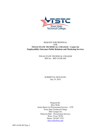
ofing2.1.22.1.2 GENERALREQUIREMENTS:FormsForms of waterproofingBS 8102 defines three forms of waterproofing protection, Type A barrier protection (commonly referred to as 'tanking'), TypeB, structurally integral protection and Type C drained protection.These drawing sheets discuss type A, B, and C protection.Example of combined waterproofing A, B, and CReinforced concrete designed and constructedto support vertical and lateral loads and to resistpenetration of waterCavity membrane fixed to retaining wallvia sealed plugsGeo-drainage membrane provides continuousdrainage space against the external tanking toreduce hydrostatic pressure. Appropriateprotection must be included over to protectduring backfillingDry lining fixed over membrane linings viawaterproof sealing plugs, or installedindependentlyWater-stops included at all constructionjoints to protect this vulnerable positionExternally applied tanking barrierExternal land drain positioned below slab leveland drained to a reliable outlet. Rodding pointsincluded to facilitate maintenanceAccessible & maintainable drainagechannel concealed within floorconstruction, linked to sump systemLand drain should be positioned below the levelof the horizontal waterproofingCavity membrane concealed within floorconstructionSump pump system within concretechamber or cast in sump liner45 line of foundation loadingnot to be undermined by landdrain MD InsuranceServicesLimited Limited2020 2020 MD InsuranceServices17 17BASEMENTSBASEMENTS
2.1.32.1.3GENERALREQUIREMENTS:REQUIREMENTS: InternalGENERALInternalenvironmentenvironmentThe degree of seepage or dampness (water tightness) that can be tolerated for this particular end use needs to beestablished and agreed with all interested parties, including the Warranty Surveyor at the design stage. To assist withquantifying an acceptable level of moisture ingress, the following definitions of water tightness are provided.Intended use and required standard of environmentUsage dictates the required 'grade' of environment, i.e. how 'dry' a given basement space must be in order to be suitable fora given usage.·The designer must therefore consider how this will be achieved in a particular site and structure. BS 8102: 2009 Table 2provides three definitions of environmental grades (Grades 1, 2 and 3) as shown in the table below:GradeExample of use of structurePerformance level1Car parking, plantrooms (excluding electricalequipment), workshops.Some seepage and damp areas tolerable,dependent on intended use.2Plant rooms and workshops requiring a drierenvironment (than Grade 1), storage areas.No water penetration acceptable.Damp areas tolerable; ventilation might berequired.3Ventilated residential and commercial areasincluding offices, restaurants, leisure centres.No water penetration acceptable.Ventilation, dehumidification or air conditioningnecessary, appropriate to the intended use.··These are taken from the publication 'Specification for piling and embedded retaining walls'.Section 2.2.3 of CIRIA Report 139 provides guidance on quantifying the required internal environment and places limits onGrade 1 basements:It identifies:·Grades of waterproofing protection·For Warranty purposes we require all basements to be designed and constructed to a minimum of Grade 2, with Grade3 being necessary for occupied space. An exception to this is a basement used solely for underground car parking,where a Grade 1 could be accepted. See 'Underground car parking' below for specific guidance.·Habitable space is Grade 3 where water penetration is unacceptable. Appropriately designed environmental controlssuch as vapour barriers, insulation, heating, ventilation and dehumidification must be included to control vapour,introduced via occupation sufficiently thereby preventing problems of condensation.·An example usage for Grade 2 includes store rooms and again, water penetration is not acceptable however, heatingand ventilation is not necessarily required, albeit that some degree of ventilation is recommended even in basic storagespace, which may otherwise suffer condensation-related dampness.Damp patch: When touched, a damp patch may leave a slight film of moisture on the hand, but no droplets of water orgreater degrees of wetness are left on the hand. On a concrete surface a damp patch is discernible from a darkening ofthe colour of the concrete.Beading of water: Beading of water is the state in which individual droplets of water (held by surface tension effects)form on the surface of the wall and adhere to the wall. The water beads do not coalesce and do not flow.Weeping of water (seepage): Weeping of water is the state in which droplets of water form on the surface of the walland coalesce with other droplets. The coalesced water does not remain stationary on the wall surface, but instead flowsdown the wall.···The functioning of mechanical plant and electrical switchgear is normally unaffected by seepage through walls andfloors, provided the water does not impinge directly onto the equipment. However, a wet floor can be hazard tomaintenance staff as well as increase the rate of corrosion of steel casings and frames in contact with it. Generally, araised working area may be desirable and all equipment should be mounted on plinths.Atmospheric moisture is unlikely to affect mechanical plant unless it is continually at such a level as to cause anunreasonable fast rate of corrosion. One exception is that air compressors need to be fitted with air-driers if they are tooperate in constantly damp conditions. Ferrous pipes, conduits, wall brackets and their fixings etc. will corrode ifunprotected.Damp air may cause electrical installations to malfunction. Permanently damp conditions may encourage biologicaldegradation of plastic insulation. Ventilation of the plant space is therefore important.Water ingress to underground car parks must similarly be controlled. Cars are likely to introduce significant amounts ofwater on wet days, which should be drained away. There is also the danger of corrosion and discoloration of paintworkon the cars due to seepage through the ceiling slab (podium deck).Summary of environmental parameters:·Underground car parking··In the case of underground car parking with associated underground refuse stores and cycle stores; some seepage,dampness or condensation as well as standing water (from vehicles) is to be expected.For this type of use, a design by water proofing design specialist to a BS 8102 Grade 1 standard could be accepted. Forplant rooms (that do not house items of plant that directly service the building), lifts/escalators, access stairs and lobbies thatare associated within an underground car park, a Grade 2 standard is the minimum grade to be expected. A Grade 2standard is the minimum grade to be expected for plant rooms (that do not house items of plant that directly service thebuilding), lifts/escalators, access stairs and lobbies that are associated within an underground car park.···Relative humidity (RH): Items stored in such basements should not normally be unduly affected by high relativehumidity. Ventilation provision draws air directly from the atmosphere and conditions equivalent to prevailingatmosphere, RH greater than 65% (normally UK external range), are therefore acceptable.Temperature: Grade 1 basement would not normally be heated.Dampness: The requirements for dampness will depend on whether the basement is to be decorated in any way andthe sensitivity of any electrical equipment to be installed (i.e. light fittings, switches, cable runs/conduits etc.). If thebasement is not to be decorated, visible damp patches may be tolerated. A higher waterproofing specification may berequired if the walls are to be painted etc. It is normally expected that the construction materials will not be wetter than85% RH.Wetness: Minor seepage would be acceptable through the walls and joints if the basement is not to be decorated.The need for drainage within the basement, i.e. channels along perimeter walls and across car parking areas, shouldalso be determined, together with requirements for ventilation.Where necessary, consideration should also be given to whether additional protection measures are required to plantand equipment, electrical switchgear, support brackets etc.Once the most appropriate level of water tightness has been determined, the Waterproofing Specialist should factor this intohis design and specify a suitable waterproofing system that will achieve the required level of performance. Full design detailsand justification of the proposed method of waterproofing must be submitted and approved by the Warranty Surveyor prior towork commencing on site. MDInsuranceServicesLimited2020 TS
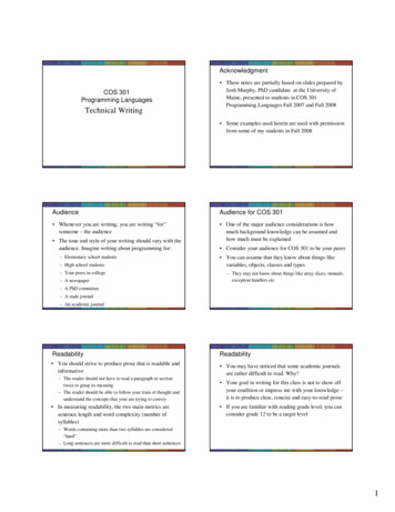
.42.1.4 GENERALREQUIREMENTS:Sub-surfaceLand Drain Positioning & External DrainageExclusion of surface waterSurfaces external of the basement structure at ground level can act to limit or attenuate penetration into vulnerablepositions, i.e. the more permeable excavated and backfilled ground directly around the basement structure. Theinclusion of surface and cut-off drains which remove standing water away from the vulnerable areas are also ofbenefit.Sub-surface drainageWhen the land drain is positionedabove top of slab level, water willstand within the excavation belowthe level of the drain beforeaccessing the drain. This canresult in hydrostatic pressureupon the structure and associatedwaterproofing. This designassumes perfect workmanship,and is not therefore acceptableunless viable proven repairstrategies are in place to addresspenetration through potentialdefectsLand drains should be includedbelow the level of the horizontalwaterproofing and this positionwould therefore be acceptablein the event of a barrier systembeing included internallyLand drain below slab level(not within 45 degree zone ofloading), preventing hydrostaticgroundwater pressure frombearing upon structure andwaterproofing45 line of foundation loading, notto be undermined by land drainThe use of land drainage can act to remove water from around the structure, thus alleviating pressure and should beconsidered in all cases to reduce the risk of water ingress where practical.However, the use of land drainage might not be viable on all sites, examples being:····Depending on the required 'environment', if land drainage is not feasible, a combination of at least two systems inorder to mitigate the risk of water ingress will need to be adopted. The Waterproofing Specialist will be required toprovide a solution specific to the site conditions.Notwithstanding such conditions, the provision of effective land drains is often an economic means of greatlyreducing risk and must be included where viable.The following considerations apply:····Note: structural slab includes'toe' detail, however the sameapplies for structures wherethis is not included···Where land drains are included this should be in association with a permeable stone backfill compacted in layers, which also encourageswater to drain down to the level of the land drains without perching and pressuring the structure.·The use of maintainable land drains is a necessity when employed in association with some forms of inaccessible/external tankingsystems, i.e. where the structure itself provides little resistance. In such cases if it is not feasible to include reliable land drains, alternativemethods of waterproofing must be used.Where there is no available location to discharge collected ground water.Where high water tables and permeable ground conditions make it impractical to sufficiently remove thequantities of water present.Restrictions on the site curtilage due adjacent buildings close to or on the site boundary.Draw down, i.e. affecting the stability of other structures by the introduction of a land drain.Perforated land drains must be surrounded in clean graded stone and wrapped in a suitable geo-textile filterfabric to reduce the risk of clogging. This is particularly important in fine granular and clay soils where landdrains are susceptible to clogging.Rodding points must be included (ideally at changes in direction) to facilitate maintenance, which will allow thesystem to function in the long term (this particularly applies to land drains where there is no viable access forrepair). This maintenance should be undertaken at suitable intervals (annually as a minimum), with the detail ofthis being written into the documentation passed to homeowners.Land drains must be positioned at a low enough position to prevent pressure from bearing upon the structureand waterproofing.The use of geo-drainage membranes applied to the external face of a retaining wall can provide a continuousdrainage space external of the structure, which assists in encouraging water to drain down to the level of theland drains without pressuring the structure.Land drains must link to a reliable point of discharge. Where sump pump systems are employed, theimplications of power cuts should be considered in that land drains may in such scenarios not function asintended. The effectiveness of battery back-up systems, where employed in sumps servicing land drains,should be considered in relation to assessment of the likely degree of ground water.Land drains must not be directly linked to soakaways by gravity, unless it is not possible for water to surcharge,i.e. where the top of the soakaway is below the level of the actual land drains.The Warranty Surveyor is to be supplied with design details where external land drainage is included. MD InsuranceServicesLimited Limited2020 2020 MD InsuranceServices19 19BASEMENTSBASEMENTS
2.Basements MD Insurance Services Limited 20202.2Waterproofing Systems20
WATERPROOFINGSYSTEMS:TypeTypeAA-- BarrierBarrier protection2.2.12.2.1 WATERPROOFINGSYSTEMS:protectionCombined protectionCommentary on Type A barrier protection·This guidance is for the protection Type A tanked (barrier) protection. A combination of forms of waterproofing may need tobe employed to substantially lower the risk, and may be necessary where the consequences of failure are particularly great,and/or where difficult site conditions result in an unacceptably high risk when employing a single system.·Type A barrier protectionThis form of waterproofing relies on the inclusion of a physical barrier material applied on or within the structure, oftenwhere the structure itself provides little resistance to the penetration of water.·A variety of considerations apply:········Suitability of the substrate, primarily applicable where tanking products are applied internally in that the bond betweenthe product and the substrate on which it is applied, must be sufficient to resist hydrostatic ground water pressure.The requirement for preparation of substrates to accept tanking mediums.Movement which in rigid tanking systems may encourage cracking through which water may penetrate, wherepressure comes to bear.Loading, where hydrostatic pressure is applied to the structure as a result of exclusion via the tanking medium, i.e.structures must be designed to resist loads applied to them.Continuity, in that systems must in virtually all cases be 'continuous'. A gap in a barrier system represents a point atwhich water under pressure can penetrate.'Buildability', namely whereby sheet membrane products are proposed with the consideration being the practicality ofwrapping a flat sheet around complex three dimensional shapes, such as external corners and beneath raft slabthickened toe details.·Other considerationsGround gases and contaminantsAggressive ground conditions may require the inclusion of a suitable ground barrier to protect the structure appropriately.Specialist advice must be sought in respect of dealing with ground gases, and designers are advised to check currentstandards at the time of construction for suitable guidance.Type A barrier protectionGeo-drainage membrane providescontinuous drainage space against theexternal tanking. Appropriate protectionmust be included over to protect duringbackfillingExternal land drain positioned below slablevel and drained to reliable outlet toprevent hydrostatic pressure bearing uponstructure. Rodding points included tofacilitate maintenanceLand drain should be positioned below thelevel of the horizontal waterproofing andhence is shown here below slab level, thisbeing below the level of the externalhorizontal tanking barrier45 line of foundationloading, not to beundermined byland drain. MD InsuranceServicesLimited Limited2020 2020 MD InsuranceServicesWhilst BS 8102 advises that 'reparability' must be considered, the use of external adhesive membrane tanking systems onpermeable constructions is precluded, unl
2. Basements shall be appropriately designed to ensure that they adequately provide a suitable barrier against contaminants, ground gases and ground water. 3. Design details of the basement waterproofing techniques must be provided prior to commencement onsite. 4. All basements must be de