Transcription
Basements: WaterproofingGeneral guidance to BS 8102:2009For more information visit:www.tbic.org.ukBasements Covers-DJK.indd 120/09/2011 13:17:05
ForewordThis publication examines the factors to consider when deciding on the form of basement construction, and types ofwaterproofing for single-storey domestic basements. It provides guidance on the form and characteristics of the maincategories of waterproofing systems: bonded sheet membranes, bentonite clay active membranes, liquid-appliedmembranes, mastic asphalt, cementitious proprietary multi-coat renders, toppings, coatings, and cementitiouscrystallisation active systems and cavity drain systems. It also contains information on soil characteristics and detailedillustrations relating to drainage, waterproofing and means of assessing risk. The guidance in this publication follows theprinciples given in BS 8102:2009, which should be referred to for more recommendations and guidance on methods ofdealing with and preventing the entry of water from surrounding ground into a structure below ground level for bothshallow and deep basements.AcknowledgementsThe Basement Information Centre is grateful for the assistance and comments provided for this publication by its Technicaland Marketing Committee and its members.TBIC also acknowledges the support given by the various organisations and individuals who contributed to the original1994 edition of this publication.A list of members providing products and services for new-build, refurbishment and retro-fitbasements may be found on The Basement Information Centre’s website www.basements.org.uk or www.tbic.org.uk, which also lists other publications and provides more informationon the design and construction of basements for dwellings.Many construction activities are potentially dangerous, so care is needed at all times. Current legislation requires allpersons to consider the effects of their actions or lack of action on the health and safety of themselves and others. Adviceon safety legislation may be obtained from any area offices of the Health and Safety Executive.TBIC/005First published 1994, 2nd edition 2011ISBN 978-0-9557526-3-6 The Basement Information Centre 2011 British Cement Association 1994Published byThe Basement Information CentreRiverside House, 4 Meadows Business ParkStation Approach, Blackwater, CamberleySurrey GU17 9ABT: 44 (0)1276 33155F: 44 (0)1276 38899E: info@tbic.org.ukwww.tbic.org.uk or www.basements.org.ukAll advice or information from The Basement Information Centre is intended for those who will evaluate the significance and limitationsof its contents and take responsibility for its use and application. No liability (including that for negligence) for any loss resulting fromsuch advice or information is accepted. Readers should note that all TBIC publications are subject to revision from time to time andshould therefore ensure that they are in possession of the latest version.Basements design guide.indd 120/09/2011 13:11:04
Basements: WaterproofingBasements: WaterproofingGeneral guidance to BS 8102:2009CONTENTSPAGEIntroduction. 1Scope.1Basement usage. 2Design principles. 2Structural waterproofing in existing structures. 8Site investigations. 9Water table. 9Ground drainage. 9Soil type and conditions. 10Movement risks that may affect basements. 12Types of waterproofing protection. 13Characteristics of the types of waterproofing protection. 16Combined/combination systems. 18Selection procedure. 19Guide to assesing basement designs. 19Assessing risk. 20Permanently low water table. 21Variable water table. 21Permanently high water table. 21Control of groundwater to reduce risk. 21Form and characteristics of waterproofing materials. 22Category 1: Bonded membranes. 22Category 2: Cavity drain membranes. 22Category 3: Bentonite clay active membranes. 23Category 4: Liquid-applied membranes. 23Category 5: Mastic asphalt membranes. 24Category 6: Cementitious crystallisation active systems. 24Category 7: Proprietary cementitious multi-coat renders, toppings and coatings. 24iiBasements design guide.indd 220/09/2011 13:11:04
Basements: WaterproofingAncilliary materials. 25Waterstops. 25Other design considerations. 28Vapour control. 28Chemical and gas barrier. 28System restraint. 28Substrate movement. 28Expansion joints. 28Defects and repair. 29Condensation. 29Thermal insulation. 29Effect of construction options. 30Basement site locations and forms. 30Design factors affecting construction. 32Waterproofing details. 34Details of waterproofing options and forms of construction. 34Glossary. 41References. 43Other publications relating to basement structures . 44iiiBasements design guide.indd 320/09/2011 13:11:04
Basements design guide.indd 420/09/2011 13:11:04
Basements: WaterproofingIntroductionBasements provide an opportunity for builders to achieve a good return on their outlay, and for their customers to benefitby being offered houses with greater potential(1). Reference 1 also provides further guidance on how basements can bea viable part of the solution for sustainable housing in the UK, through consideration of Planning Policy, the Code forSustainable Homes and their development benefits, and the key issues to be considered at each stage of the design andconstruction process for single-storey basements for domestic housing.Including a basement maximises available land space, provides more stable construction, is thermally efficient and offersideal quiet areas and further space for storage or accommodation. Basements can be economically introduced onto mostsites(2) and, in particular, have clear advantages on sites with poor ground that may otherwise be regarded as difficult andpossibly uneconomic to build on. This publication follows the guidance given in BS 8102:2009(3) and is intended to helpthe builder or designer arrive at the most appropriate form of construction and waterproofing solution. Further guidanceon design matters for basements may be found in Reference 4.A best practice guide to the design and construction of concrete basements(5) aims to assist generalist structural engineers,who have some grounding in soil mechanics, with the design of basements with modest depth (say, not exceeding 10 m).It covers the salient features for the design and construction of such basements in accordance with the Eurocodes.ScopeThe details and comments given in this publication are generally limited to Grade 2 and 3 internal environments, asdefined in BS 8102, where no water penetration acceptable, which are appropriate for residential basements.The Grade 2 environment is for use as workshops and plant rooms, and other areas where the performance level permits nowater penetration, but higher levels of water vapour would be tolerable and surface condensation may occur.The Grade 3 environment is for ventilated residential and working areas which require a drier environment.1Basements design guide.indd 120/09/2011 13:11:04
Basements: WaterproofingBasement usageTable 1 relates environmental performance levels to basement usage, and defines them from Grades 1 to 3. Mostbasements will be for domestic accommodation, which is Grade 3. Grade 1 environment can from BS 8102 be suitablefor car parking but this allows some leakage, which will likely not be desirable or acceptable for domestic garages. Somedomestic basements may be for permanent workshops or garages, and a Grade 2 environment may be acceptable.However, since usage may change, it is better to construct a basement to a Grade 3 environment than to upgrade itlater.Guidance with respect to ventilation may be found in References 6 and 8.Table 1 BS 8102 Grades of waterproofing protectionGradeExample of use of structurePerformance level1Car parking; plant rooms (excludingelectrical equipment); workshopsSome leakage and damp areas tolerable, dependent on the intended use A)Local drainage might be necessary to deal with leakage2Plant rooms and workshops requiring adrier environment (than Grade 1); storageareasNo water penetration acceptableDamp areas tolerable; ventilation might be required3Ventilated residential and commercialareas, including offices, restaurants etc.;leisure centres B)No water penetration acceptableVentilation, dehumidification or air conditioning necessary, appropriateto the intended useLeakage and damp areas for some forms of construction can be quantified by reference to industry standards, such as the ICE’sSpecification for piling and embedded retaining walls (7).B)Archives, landmark buildings and stores requiring a controlled environment need special consideration, e.g. see BS 5454 forarchives(8).A)BS 8102:1990 referred to Grade 4 environments. However, this grade has not been retained as its only differencefrom Grade 3 is the performance level related to ventilation, dehumidification or air conditioning (see BS 5454 forrecommendations for the storage and exhibition of archival documents). The structural form for Grade 4 could be thesame or similar to Grade 3.The attainment of environmental performance is achieved by attention to waterproofing design principles, a selectionprocedure – which requires consideration of structural form, and selection of appropriate waterproofing materials – andother design considerations. These are dealt with in the following sections.2Basements design guide.indd 220/09/2011 13:11:04
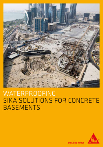
Basements: WaterproofingDesign principlesSpecialist inputThe specification of waterproofing systems is a specialised task. It is recommended that, once the design team has giventhe system some thought, an appropriate specialist should be contacted immediately for early advice and help on thewaterproofing design. This is a fundamental change introduced into BS 8102.GeneralBS 8102 indicates that in order to develop a robust design for protecting a structure against groundwater, the followingfactors should be assessed:a)the likely highest level of the water table, the drainage characteristics of the soil and other site-specific properties;b) the appropriate waterproofing measures, i.e. Type A, B or C protection (see Types of waterproofing protection) and,where necessary, external drainage based on:1)the results of the site evaluation, including the classification of the water table; and2) the intended use of the structure, with consideration given to any requirement for future flexibility. This shouldbe undertaken in consultation with the client;c)the appropriate type of primary waterproofing system.There are other factors that need to be taken into account as given in both BS 8102 and within this publication butchoosing a suitable basement construction may in simplistic terms be divided into four main steps: Decide on basement usage.Gather site information.Decide on form of construction and type of waterproofing.Assess buildability and reparability.The general principle is to assess the risk of water reaching the structure and the nature of the structural options withrespect to water resistance and then to select a waterproofing system appropriate to achieving the required basementinternal environment.Figure 1 outlines by way of a flowchart the principal factors and stages that need to be addressed in order to produce arobust waterproofing solution for a below-ground structure. This figure and the principles outlined in this section followthe philosophy given in BS 8102.The directional arrows in Figure 1 indicate that some matters are interrelated, and that a degree of iteration might resultfrom a need to also address suitability, buildability and reparability. The principal issues (Figure 1) do not necessarily needto be addressed in the order shown but all will need to be understood and evaluated.3Basements design guide.indd 320/09/2011 13:11:04
Basements: WaterproofingINITIAL INFORMATIONDesign philosophy* Design teamSite evaluation* Desk study* Risk assessment* Water table classification* Ground contaminantsReview of structureBuilding type* Type (e.g. new or existing)* Intended use* Foundation form and design* Construction methodologySTRUCTURAL DESIGN CONSIDERATIONSSELECTION OF TYPE A, B or CWATERPROOFING PROTECTIONIS COMBINED PROTECTION NECESSARY?SELECTION OF PRIMARYWATERPROOFING SYSTEMHAS BUILDABILITY BEEN CONSIDERED?NOHAS REPAIRABILITY BEEN ADDRESSED?YESSOLUTIONFigure 1 Design flowchartOther factors that need to be determined and/or addressed in order to develop a robust design for protecting a structureagainst groundwater are: the level of protection needed based on the intended use of the structure, with consideration given to anyrequirement for future flexibility. This should be undertaken in consultation with the client (see Basement usage); the position of the water table, the drainage characteristics of the soil and other site-specific properties(see Selection procedure) and the implications of constructing a new basement with regard to the likelygroundwater characteristics; the need for continuity in waterproofing protection, taking into account the proposed type of foundations(see Design factors affecting construction); the appropriate type of waterproofing protection, i.e. Type A, B or C (see Type of waterproofingprotection); and the appropriate type of primary waterproofing system (see Form and characteristics of waterproofing materials).4Basements design guide.indd 420/09/2011 13:11:05
Basements: WaterproofingIt is important, particularly for new-build basements, that the structural, building services, overall building weatherproofingdesign and basement waterproofing designs are considered together, as they will normally interact.A two-dimensional drawing shows a simple profile but a three-dimensional review of the structure and waterproofingshould be undertaken so as to identify any complex geometries which will not be readily identified from normal twodimensional details. An example is given in Figure 2, which shows the effect of applying a waterproofing barrier to athickened-edge slab (Figure 2(a)) compared to a slab of constant thickness (Figure 2(b)). In Figure 2(a) the mitred corner tothe underside of the slab can cause problems in correctly applying some waterproofing barriers, which can lead to defectsand the need for repair. The section with constant thickness indicated in Figure 2(b) allows for easier and more reliablewaterproofing to be applied to the underside of the slab. This example shows how simplifying the structural shape canease the application of the waterproofing and render it more reliable.Membrane required to be placedMembrane required to be placedinto underslab corner juction,into underslab corner juction,which can be difficult to formwhich can be difficult to formwithout defects; preformedwithout defects; preformedsections generally not available.sections generally not available.waterproofingwaterproofingmembrane shownmembrane shownfollowing thickenedfollowing thickenedprofileprofilePlan view at cornerPlan view at cornerCross-sectionCross-sectiona) Slab with thickened edge complicates the application of a waterproofing barriera) Slab with thickened edge complicates the application of a waterproofing barriera) Slab with thickened edge complicates the application of a waterproofing barrierSimpler square corner (No mitre)Simpler square corner (No mitre)Waterproofing membraneWaterproofing membraneon rectangular profileon rectangular profileCross-sectionCross-sectionPlan view at cornerPlan view at cornerb) Slabconstantthicknessthickness canapplicationof a waterproofingbarrierbarrierb) Slabof ofconstantcan simplifysimplifythetheapplicationof waterproofingb) Slab of constant thickness can simplify the application of a waterproofing barrierFigure 2 A & B Effect on waterproofing when assessed on a three-dimensional basisConcrete/steelConcrete/steelpiled wallpiled wallBasements design guide.indd 5Waterstop atWaterstop atjunction to followPiled wall might need toPiled wall might need tobe faced to achievebe faced to achievedesired water resistancedesired water resistance520/09/2011 13:11:05
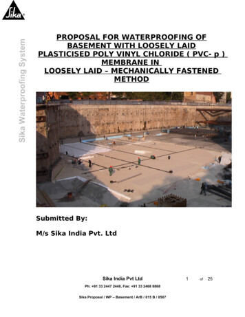
Basements: ytrayThe design should also cater for, or enable, post-construction treatments to enhance performance or to overcome possibledeficiencies in the waterproofing construction.InternalwaterproofingFigure 3 is used to illustrate the benefit in considering the need for possible repair as this can lead to a more robust design.Consult withConsult withExternalFigure 3(a) shows an original designmanufacturersthat utilised a Type B construction, with an oversailing cavity wall havingthe inner leafmanufacturerswaterproofingfor specificdetail developfor specificdetailcarried down past the principal retainingwall.This, when examined, highlights the fact that should a defect(crack)in the external basement wall the incoming water could track around the cavity (and enter a considerable distance away).In addition the internal leaf of the cavity wall also prevents access to repair the basement wall. By considering a structure inwaycan leadto a reassessmentof design – for example in Figure(b3(b),wherebya drainablewithchannelortrayType C membrane) Linkingof internal waterproofingDPC/cavityLinkingof exernalwaterproofingwith DPC/cavity tray(a) thissystem could be incorporated within the cavity. External subsoil drainage could also be used to lessen risk. Figure 3(c) showsthe external retaining wall thickened to support the oversailing masonry wall, which then allows direct access to the wall in theevent of a defect, for example to enable crack injection. Again external drainage would, in appropriate condition, lessen risk.Cavity preventsaccess for repairDrainage channelor Type C watermanagement systemto lower riskConstruction nowallows accessfor repairappropriate sub-surface drainagecan also be included to lessen risk(a) Structure designed forwater resistance (Type B)(b) Redesigning with cavity drainagesystem lessens risk(c) Redesigning with thicker wall enhancesresistance and enables access for repairFigure 3: Consideration of need for repair leading to an alternative designFigure 3 is used in this publication prior to examining the principal forms of waterproofing protection and characteristics ofwaterproofing materials as it highlights an important design issue often overlooked in the past. This reflects and highlightsthe need to address buildability and reparability as introduced into BS 8102: 2009.Another important design principle is to ensure that adequate details are provided for the system in general (e.g. wall basedetails, laps in membranes), or changes in level of the slab, or at the head of the wall where it adjoins the superstructureand/or at windows that extend below ground level (see Waterproofing details).The structure should also be analysed as a three-dimensional box, particularly for Type B (structurally integral) construction.And where serviceability cracking could have a detrimental effect on an applied waterproofing.Figure 4 shows typical bending moment distributions on both vertical cross-sections and horizontally. It would also bebeneficial to assess these bending moments taking some account of soil–structure interaction as this will more accuratelydetermine ultimate and serviceability stresses, and thereby result in more design control of water resistance.6Basements design guide.indd 620/09/2011 13:11:05
Basements: WaterproofingGround floorBasement wallsVertical bending moments inwalls and moments in raftGround floorRaft foundationCross sectionBasement wallsVertical bending moments inwalls and moments in raftBasement wallsHorizontal bending Raft foundationmoments in wallsCross sectionPlan viewFigure 4 Bending momentsin wallsand raftfoundationFig 4 Bendingmomentsin wallsand raft foundationHorizontal bendingmoments in wallsBasement wallsIn analsounreinforcedSimilarly, the effect of plain and reinforced concrete structures shouldbe taken into account when selecting thewall, crack width isStressandcrackwidthapplied waterproofing membranes. BS 8102 indicates that barrier-specificpropertiesshould be evaluated, to ensureless controlledcontrolled by reinforcementthat they can cater for any predicted cracking from the structure (see Figure 5). Barrier materials will typically acceptlocal strains and cracking ina reinforcedconcrete structure, but somemay notso readily cater for the wider cracks in aMay exceedstrainLikleyto be comptaiblecapacityofsomeplain (unreinforced) sentedin Figure 1 by the directional arrowswith most waterproofingwaterproofingmembranesbetween selection of waterproofingand types of Fig 4 Bending moments in walls and raft foundationStress and crack widthcontrolled by reinforcementIn an unreinforcedwall, crack width isless controlledUnreinforced wall or nominalReinforced wallMay exceed strain reinforced (in-situ/masonry)Likley to be comptaiblecapacity of somewith most waterproofingwaterproofingmembranesFig 5 Effect of structure membraneson applied waterproofing barrierUnreinforcedwallor nominalFully bondedReinforcedmembrane wallPartiallybondedreinforced(in-situ/masonry)does not allow water tomembrane can allowtrack from a defect inwater to track from amembrane to adefect in a membrane to aFigure 5 Effect of structureon appliedwaterproofing barriercrack//jointin thecrack/joint in theFig5 Effect ofstructure on applied waterproofing barriersupporting concrete wallsupporting concrete wall.7Basements design guide.indd 7Fully bonded membranePartially bonded20/09/2011 13:11:06
Basements: WaterproofingStructural waterproofing in existing structuresMany of the considerations applicable to structural waterproofing design in new construction apply equally to thedesign of systems for existing structures, and this document serves equally well as a guide to review these necessaryconsiderations for this purpose.However, contrary to new-build scenarios, there are limitations inherent when working within the confines of anexisting structure, in that there is typically a limited opportunity or scope to make structural alterations for the purposeof installing a given system.Additionally, while in the case of new construction waterproofing, the designer is providing the initial or first-stagemeasures of protection against groundwater, in existing structures it is often the case that designs are provided for thepurpose of remedying failures in those initial measures, to address problems with systems of considerable age in olderor historic property, or to facilitate change of use.If options are limited by the confines of the structure, it is important to understand what that structure is, and equally,the nature of any installed waterproofing measures within it, which may further influence design.Therefore, an analysis, through visual inspection, inspection of drawings (where available), and potentially intrusiveinvestigation, i.e. trial hole formation, should be undertaken so that a thorough understanding of the structure and howit is constructed, is developed. The effects of any structural discontinuity (see Figure 11(a)) as may typically occur in anexisting structure must also be assessed.Once the structure is understood, and objectives and instructions are defined, it is the role of the waterproofingdesigner to configure products and systems within that structure, all while considering the appropriate factors detailedwithin this guide, so that the objectives are successfully met and structures are protected in the long term.Much of the failure associated with structural waterproofing is attributable to insufficient consideration of the relevantfactors, leading to poor design, It is therefore advisable that where specifying waterproofing, these factors are examinedrigorously, and that ideally specialists be consulted about a design at the earliest stage.8Basements design guide.indd 820/09/2011 13:11:06
Basements: WaterproofingSite investigationsAspects of gathering site information are dealt with in the subsections that follow but there are some overridingprinciples that need to be highlighted when selecting the form of construction and waterproofing system. High water tables present the greatest risk of failure to the waterproofing of a basement and it is thereforeimportant to identify it. A watercourse or water table that rises and falls and the potential for a perched watertable must also be identified. How often and for how long the water table stays high are also important factors.If the water table rises briefly – say, after heavy rain – and then immediately falls again, the risk of waterpenetration through external waterproofing and then through the structure is less than if the water table stayshigh for a much longer period. Consideration may also need to be given to the effect o
on design matters for basements may be found in Reference 4. A best practice guide to the design and construction of concrete basements (5) aims to assist generalist structural engineers, who have some grounding in soil mechanics, with the design of baseme