Transcription
seoides vud ngcl n iin r a itow sN rkoWlidVSoBeginner’s Guide toSolidWorks 2014 Level IideosParts, Assemblies, Drawings, PhotoView 360and Simulation XpressAlejandro Reyes MSME, CSWP, CSWISDCP U B L I C AT I O N SBetter Textbooks. Lower Prices.www.SDCpublications.comMultimedia DiscIncludes SupplementalFiles and VideoInstruction
Visit the following websites to learn more about this book:Powered by TCPDF (www.tcpdf.org)
Special FeaturesSpecial Features: Sweep, Loft and WrapThere are times when we need to design components that cannot beeasily defined by prismatic shapes. For those features that have ‘curvy’ shapeswe can use Sweep and Loft features, which let us create almost any shape wecan think of. These are the features that allow us to design consumer products,which, more often than not, have to be attractive and appealing, makingextensive use of curvature and organic shapes. These products include thingslike your remote control, a computer mouse, coffee maker, perfume bottles,telephones, etc., and many times the success or failure of these products in themarket can be directly attributed to their appearance. They have to look nice,‘feel’ right, and of course perform the task that they were intended for. Sweepsand Lofts (also used to create “organic” shapes like those found in nature) arewidely used in the automotive and aerospace industry where cosmetics,aerodynamics, and ergonomics are very important in the design.Sweeps and Lofts have many different options that allow us to createanything from relatively simple to extremely complex shapes. In light of the vastnumber of variations and possibilities for these features, we’ll keep theseexamples as simple as possible without sacrificing functionality, to give thereader a good idea as to what can be achieved.Sweeps and Lofts are usually referred to as advanced features, since theyusually require more work to complete, and a better understanding of the basicconcepts of solid modeling. Having said that, these exercises will assume thatcommands that we have done more than a couple of times up to this point, likecreating a sketch, are already understood and we’ll simply direct the reader tocreate it providing the necessary details. This way we’ll be able to focus more onthe specifics and options of the new features.The Wrap feature is a special tool that helps us, as the name implies, to'wrap' a sketch around a cylindrical surface, this tool helps us create features likecylindrical cams, slots on cylinders or cylindrical surfaces, etc.185
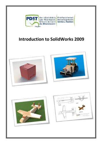
Beginner’s Guide to SolidWorks 2014 – Level IThese are examples of designs made using advanced modeling techniques.186
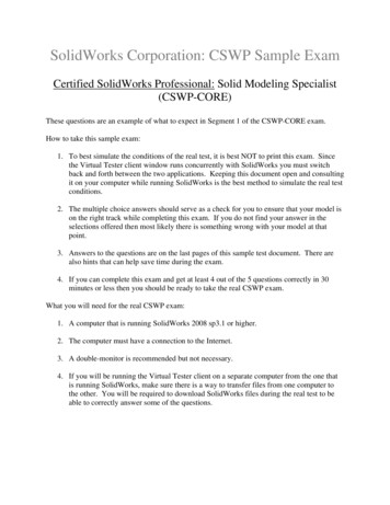
Special FeaturesSweep: Cup and Springs187
Beginner’s Guide to SolidWorks 2014 – Level INotes:188
Special FeaturesFor this exercise we are going to make a simple cup. In this exercise wewill learn a new option when creating features called “Thin Feature,” the Sweepcommand, a new Fillet option to create a Full Round fillet and a review ofauxiliary Planes. The sequence of features to complete the cup is:Revolve ThinCreate Path SketchAuxiliary PlaneCreate Profile PathMake SweepCut inside of CupFull Round FilletHandle Fillet149. – For the first feature we will create a “Revolved Feature” using the “ThinFeature" option. This option makes a feature with a specified thickness based onthe sketch that was drawn. Select the "Front Plane" and create the followingsketch. Notice the sketch is an open profile with two lines, an arc and acenterline. (Remember to make the diameter dimension about the centerline.) aThin Feature can be made using either an open or closed sketch, but using anopen sketch will always make a thin feature.189
Beginner’s Guide to SolidWorks 2014 – Level I150. - After selecting the “Revolve Boss/Base” command we get a warningtelling us about the sketch being open. Since we want a thin revolved feature,select “No."In the “Revolve” options, “Thin Feature” is automatically activated. Sincewe want the dimensions we added to be external model dimensions, select theThin Feature’s “Reverse Direction” option to add the material inside the cup.Notice the preview showing the change.In the value box we typed 3/16; we can add a fraction and SolidWorkschanges it to the corresponding decimal value when we click OK. We canalso type simple mathematic expressions including addition, subtraction,multiplication, and division in any value box where we can type a value.190
Special FeaturesOur part looks like this and “Revolve-Thin1” is added to the Feature Manager.151. - Select the "Front Plane" and create the following sketch using an ellipse.Add a “Vertical” geometric relation between the top and bottom points of theellipse to make them vertical to each other and fully define it. Select the “Ellipse”command from the Sketch tab in the CommandManager or from the menu“Tools, Sketch Entities, Ellipse." Add the corresponding dimensions to andfrom the ellipse points at the major and minor axes. To draw an ellipse click tolocate the center point, click again to locate one axis and then the other axis.When looking at a round surface from a front, side ortop view we can add a dimension to its silhouette.191
Beginner’s Guide to SolidWorks 2014 – Level IExit the sketch and rename it "Path Sketch." We will not use the sketch for afeature just yet.152. - Create an Auxiliary plane parallel to the "Right Plane" using the plane asthe first reference and the center of the ellipse as a second reference as shown.Click OK to finish the plane.192
Special Features153. - Select the plane just created and draw the next sketch in it. Looking at theplane perpendicular to it helps to visualize the sketch. After adding the sketchpress the “Normal To” command (shortcut Ctrl 8.) Pressing it again will show thereverse view. Start the center of the new ellipse at the top point of the previoussketch's ellipse. Add a coincident relation if needed. Remember to add ahorizontal relation between the points of the major (or vertical to the minor) axis.If necessary rotate the part to better visualize and select the top point ofthe ellipse in the previous sketch. Exit the sketch and rename it "Profile Sketch."193
Beginner’s Guide to SolidWorks 2014 – Level I154. - Select the “Sweep” icon from the Features tab in the CommandManageror from the menu “Insert, Boss/Base, Sweep.” The sweep is a feature thatrequires a minimum of two sketches: one for the sweep’s profile and one for thepath (For the path of the sweep instead of a sketch we can also use a modeledge or a user defined curve that cross the profile.)In the “Sweep” properties, select the "Profile Sketch" in the Profileselection box, and the "Path Sketch" in the Path selection box. Optionally, aSweep can have guide curves and other parameters to better control theresulting shape; in our case we are making a simple sweep feature. Notice thepreview and click OK when done to finish the sweep. Hide the auxiliary planesusing the “Hide/Show Items” toolbar if so desired.194
Special Features155. - Notice the sweep also goes inside the cup. To fix the cup we’ll make a cut.Create a sketch in the flat face at the top of the cup.Select the inside edge at the top and use “Convert Entities” from theSketch tab to convert the edge to sketch geometry.195
Beginner’s Guide to SolidWorks 2014 – Level ISelect the “Extruded Cut” icon and use the “Up to next” end condition from thedrop down selection list. This end condition will make the cut until it finds the nextface (the bottom) effectively cutting the part of the handle inside the cup.156. - Now we need to round the flat face at the top lip of the cup. To do this we’lladd a “Fillet” using the “Full Round Fillet” option. The full round will essentiallyremove the flat face at the top, and replace it with a rounded face.BeforeAfter196
Special FeaturesWe need to select three faces, the middle face will be the one replaced by thefillet. After selecting the Fillet command, select the "Full round fillet" option toreveal the selection boxes. With the first selection box active select the outsideface of the cup. Click inside the second selection box and select the top flat faceof the cup. Click inside the third selection box and select the inside face of thecup. Note the selected faces are color coded. When done selecting faces clickOK to apply the fillet.157. - To finish the cup add a fillet to round the edges where the handle meetsthe cup. Select the fillet command with the “Constant Radius” option, select thehandle's surface, and change the radius to 0.25 . Click OK to finish.197
Beginner’s Guide to SolidWorks 2014 – Level I158. - Save the finished part as ‘Cup’ and close.198
Special FeaturesIn the next exercise we are going to show how to make a simple and avariable pitch spring. In order to make these springs we’ll have to learn how tomake a simple and a variable pitch helix to be used as a sweep path. Thesequence of features to complete the springs are:Simple SpringDraw circleDraw Spring ProfileSketchMake HelixMake SweepVariable Pitch SpringDraw circleMake Variable PitchHelixDraw Spring ProfilesketchMake Sweep and cutendsSimple Spring159.- In order to make a helix, first we need to make a sketch with a circle. Thiscircle is going to be the helix’s diameter. Select the "Front Plane" and make asketch using the following dimensions. Exit the sketch when done.199
Beginner’s Guide to SolidWorks 2014 – Level I160. - In the Features tab select “Curves, Helix and Spiral” from the drop-downicon or the menu "Insert, Curve, Helix/Spiral." If asked to select a plane or asketch, select the sketch we just drew.If we don't exit the sketch, we'll only have the "Helix and Spiral" option fromthe "Curves" command. If we select the “Helix and Spiral” before exitingthe sketch, it will be automatically selected.161. - The helix can be defined by the combination of two parameters, Pitch,Revolutions, or Height and the third parameter is calculated from the other two.For this example we'll select “Pitch and Revolution” from the “Defined By:”drop down menu, and make the pitch 0.325" and 6 Revolutions. The “StartAngle” value defines where the helix will start. By making it 90 degrees it will startat the top, coincident with the "Front Plane." If we had made it 0 degrees, it wouldbe coincident to the "Top Plane" instead (Feel free to explore the options.) ClickOK to finish the helix.200
Special FeaturesNote the Helix command has options to make it Counterclockwise,Clockwise, Tapered, Variable pitch and reversed (going right or left.)162. - Once the Helix is done, we need to make the profile sketch for the sweep.Switch to a Right view, and add a new sketch in the "Right Plane" as shown.Make the circle close to the Helix and add a “Pierce” geometric relation between the center of the circle and thehelix. This way the path will start at the beginning of the helix. This relation willmake the sketch fully defined. Exit the sketch when done.A pierce relation is done between an element that is oblique orperpendicular to the sketch plane and a point in the sketch. Think of it as aneedle piercing through a fabric, the sketch being the fabric and the helix(or curve, model edge or another sketch) the needle.201
Beginner’s Guide to SolidWorks 2014 – Level I163. - Select the Sweep command and make the sweep using the last sketch asa profile and the Helix as a Path. Note the Preview and click OK to finish.Save as 'Spring' and close the finished spring.202
Special FeaturesVariable Pitch Spring164. - For the variable pitch spring we’ll start the same way and make thefollowing sketch in the "Front Plane." This will be the spring’s outside diameter.165. - While still editing the sketch, in the Features tab from the “Curves” dropdown icon select “Helix and Spiral”; notice it is the only option available.166. - In the Helix/Spiral command select “Pitch and Revolution” from the“Defined by:” selection box and “Variable Pitch” in the Parameters box. Afterselecting it we are presented with a table, fill in the values for the helix using thenext table. Click OK when finished to build the helix.203
Beginner’s Guide to SolidWorks 2014 – Level I167. - After the helix is complete add a new sketch in the "Right Plane." Draw thecircle first, then add a center rectangle; trim and dimension as needed.168. - Add a centerline from the center to the top line (make sure it is coincident.)Add a “Pierce” geometric relation between the top endpoint of the centerline andthe helix to fully define the sketch. Exit the sketch and optionally rename it'Profile'.The Pierce relation allows us to fix the profile to the path, and can beadded to any part of the sketch. We chose to add it to the top because theoriginal sketch used for the helix is the spring's outside diameter.169. - Just as we did before, select the "Sweep" command, add the path andprofile as shown and click OK to finish.204
Special Features170. – As a finishing touch we’ll make a cut to flatten the sides of the spring.Change to a Right view and add a sketch in the "Right Plane." Draw a single linestarting at the midpoint of the indicated edge and long enough to cross the part.171. - Select the “Extruded Cut” command. When we use an open sketch tomake a cut, the "Through All" option is automatically selected in both directions.One side of the model is cut using the open sketch. The small arrow located atthe center of the line indicates which side of the model will be cut. Use the “Flipside to cut” option if needed to cut the left side. Click OK to complete the cutextrude and repeat it in the right side. Note the cutting plane is shown in thegraphics area.205
Beginner’s Guide to SolidWorks 2014 – Level IWhen using an open sketch to cut a model, we can only use a single openprofile. If we have multiple open profiles we cannot make the Cut Extrude.Save the model as 'Variable Pitch Spring'.A note about threadsThreads can be added to a model either by adding a Sweep or a CutSweep with a helix. When modeling screws and fasteners in general, it isalmost always unnecessary to add a helical thread, as it consumes alarge amount of computing resources, and a simple representation of itusually suffices (as a Revolved Boss/Cut or Cosmetic Thread.) It is stronglyadvised to only add threads when required by the model, as in the followingbottle exercise.206
Special FeaturesFor the next exercise we'll build the following bottle using a sweep featurewith guide curves.In this model we’ll use two sweep features, one for the body and one for thethread. For the body we'll make a sweep with two guide curves, so we need tomake four sketches: Path, Guide Curve 1, Guide Curve 2 and Profile, in thatorder. The reason to make the Profile last is that it has to pierce the Path andboth Guide Curves for the sweep to work as expected.207
Beginner’s Guide to SolidWorks 2014 – Level I172. - Open a new part, set dimensions to inches, and three decimal places.Make the Path sketch in the "Front Plane" and Exit the sketch. Rename 'Path'.173. - Add a second sketch in the "Front Plane." Make arcs and lines tangent toeach other; add centerlines as reference for tangency. All arcs are equal. Exitsketch and rename 'Guide 1'.208
Special Features174. - Add third sketch to "Right Plane." Add geometric relations to previoussketches to maintain design intent. Make the topmost endpoint Horizontal to thetopmost endpoint of the 'Path' sketch. Arcs are equal size and tangent. Make theindicated endpoints horizontal. Only geometric relations and two dimensions areneeded to fully define the sketch. Exit the sketch and rename it 'Guide 2'.Right viewView between front and right175. - Add a new sketch in the "Top Plane", make an ellipse adding Piercerelations between the ellipse's major and minor axes to 'Guide 1' and 'Guide 2'.View is in Isometric for clarity. Exit the sketch and rename it 'Profile'.209
Beginner’s Guide to SolidWorks 2014 – Level I176. - Select the "Sweep Boss/Base" icon, add the 'Path' sketch to the "Path"selection box and the 'Profile' sketch to the "Profile" selection box. Expand the"Guide Curves" selection box and add both guides to it. Click OK to finish.177. - Add a sketch on the top face, use "Convert Entities" to project the edgeof the top circular face 210
Special Features and extrude it 1".178. - Add a 0.375" fillet at the bottom of the bottle.179. - Add a 0.050" shell to the part removing the top face.211
Beginner’s Guide to SolidWorks 2014 – Level I180. - Add a parallel auxiliary plane 0.125" below the topmost face.181. - Add a sketch in this plane. Use “Convert Entities” to project the topoutside edge and make a Helix defined by Pitch and Revolution using 0.2" forpitch and 2.5 revolutions. Make sure the Start Angle is at 0 degrees.212
Special Features182. – Rotate to a Right View and add the following sketch in the "Right Plane" tobe the Profile of the thread. Be sure to add a Pierce relation between the profileand the helix at the end of the construction line. Exit the sketch and make asweep feature using the previous helix and this profile.183. - Add a sketch to the flat face at the beginning of the thread, and another atthe end of the thread using “Convert Entities.” Make a 120 degrees "RevolvedBoss" with each sketch using the vertical edge as axis of revolution. The reasonto make it 120 degrees is to merge to the body of the bottle.213
Beginner’s Guide to SolidWorks 2014 – Level I184. - Add a 0.02" fillet to the thread as a finishing touch. You may need to selectmultiple edges. Save the part as Bottle and close it.214
Special FeaturesEngine Project Parts: Make the following components to build the engine. Savethe parts using the name provided. High resolution images are included in theaccompanying disc.215
Beginner’s Guide to SolidWorks 2014 – Level I216
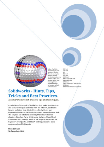
Special FeaturesLoft: Bottle217
Beginner’s Guide to SolidWorks 2014 – Level INotes:218
Special FeaturesThe “Loft” feature requires at least two different sketches and/or facesand optionally guide curves to more accurately define the final shape. The Lofthelps us design complex shapes with more control over the cross section. In thisexercise we will make a bottle using a loft with four different sketches.185. - Make a new part and create three auxiliary planes using the “Plane”command. Select the "Top Plane" as reference, change the number of planes to3 and space them 2.5 as shown. Click OK when done.186. - For clarity, select the "Top Plane" in the FeatureManager and show itusing the “Hide/Show” command from the pop-up toolbar. Turn on Plane visibilityif needed in the “Hide/Show Items” command.219
Beginner’s Guide to SolidWorks 2014 – Level I187. - Switch to a Top view, select the "Top Plane" and draw the following sketchusing the “Center Rectangle” and “Sketch Fillet” tools. Exit the sketch whenfinished. Plane visibility is turned off for clarity.188. - Still in the Top view, select “Plane1” from the FeatureManager and createthe second sketch. Use the "Center Rectangle" tool; be sure to start in the originand make the rectangle's corner coincident to the previous sketch's diagonal line.Add a 2.5 width dimension and the 0.5 “Sketch Fillet” to fully define the sketch.Exit the second sketch when finished.Turn off the display of Planes for clarity with “Hide/Show Items."220
Special Features189. - For the third profile, select “Plane2” from the FeatureManager and create anew sketch in it. This sketch will be exactly the same as the first one. To help ussave time and maintain design intent, we'll use the “Convert Entities” tool. In the“Convert Entities” selection box, select the entire “Sketch1” from the fly-outFeatureManager and click OK to project Sketch1 in the new sketch. Exit thesketch when done.190. - For the last profile select “Plane3” from the FeatureManager and create anew sketch. Draw a circle and add a geometric relation to make it “Tangent” tothe horizontal line in “Sketch2” as indicated. This relation will fully define thesketch. Exit the sketch to finish.221
Beginner’s Guide to SolidWorks 2014 – Level I191. - The finished sketches will look like this with the planes visible:192. - Now we are ready, select the “Loft” icon from the Features tab. The loftfeature requires two or more sketches and/or faces, and we'll use the foursketches we just made to build the bottle.We will select the profiles in order starting with the first one we made atthe bottom and finishing with the last one at the top (or from top to bottom, but inorder.) It is important to select the sketches thinking that where we select theprofile will affect the result. Click in the graphics area near the indicated ‘dots’,this line indicates the segment of one profile that will be connected to the nextprofile. If we select points randomly in the profiles, the loft could twist andproduce undesirable results. Optionally guide curves can be added to improvecontrol of the resulting shape.222
Special FeaturesFrom the “Start/End Conditions” select “Normal to Profile” for both the“Start” and “End” constraint. Notice the difference in the preview after selectingthe start and end constraints. Click OK when done.193. - Add a 0.25 radius fillet in the bottom edge of the part to round it off.223
Beginner’s Guide to SolidWorks 2014 – Level IAdd a 0.75” extrusion at the top of the bottle and finish using the “Shell”command removing the top face making the wall thickness 0.125 .224
Special FeaturesImage shown using Real View225
Beginner’s Guide to SolidWorks 2014 – Level I194. - To view the inside of the part, select the “Section View” icon from theView toolbar or the menu "View, Display, Section View." We can define whichplane to cut the model with, the depth of the cut and optionally add a second orthird section. If we click OK in the Section View, the model will be displayed ascut, but this is only for display purposes; the part is not actually cut. To turn offthe Section View, select its icon or menu command again. This section view canbe used along with the “Measure” tool to inspect the part.1We can also change the depth of the cut by dragging the arrow in thecenter of the plane.Save the part as 'Bottle Loft' and close.226
Special FeaturesWrap FeatureThe wrap feature helps us create cylindrical cams or slots on cylindrical surfacesusing a sketch on a plane tangent to the surface we want to make the wrap on.195. – Make a new part, set units to inches with three decimal places; add thissketch on the "Front Plane" and extrude it 3".196. – The next step is to make the sketch that will be used for the wrap feature.For the sketch plane we’ll make a plane parallel to the "Top Plane" tangent to thecylindrical surface. Add a new plane parallel to the “Top Plane” 0.75” above anddraw the following profile making sure it’s symmetrical about the centerline. Allarcs are equal radii. The top dimension's value is entered as 1.5 * pi, since wewant the sketch to wrap completely around the cylinder. SolidWorksautomatically calculates the resulting value for us.227
Beginner’s Guide to SolidWorks 2014 – Level I197. -The sketch so far is the centerline of the slot we are going to wrap aroundthe cylinder. Select the "Offset" command and turn on the options:"Select chain" to automatically select the entire centerline picking only onesegment, "Bi-directional" to make the offset in both directions, "Make baseconstruction" to change the selected line (or chain) to construction geometry,and after selecting a segment of the sketch the "Cap ends" option is enabledletting us choose to cap the offset with Arcs or Lines. Making the offset 0.25" willgive us a 0.5" wide slot. Click OK to complete the offset and exit the sketch. Notehow the previously drawn sketch lines are now changed to construction geometryand now we have a closed profile. Exit the sketch when done.228
Special Features198. – Select the "Wrap" feature from theFeatures tab or the menu "Insert, Features,Wrap."If the sketch is not pre-selected, select the sketch from the graphics area or thefly-out FeatureManager.199.- In the “Warp” command properties select the "Deboss" option to make acut in the part (The "Emboss" option will add material and the "Scribe" will splitthe face.) Select the cylinder's face in the "Face for Wrap Feature" selection box,activate the “Reverse Direction” option* and make the depth 0.1". Click OK tofinish.* As of the writing of this book, if the “Reverse Direction” option is not checkedthe wrap feature produces incorrect geometry.229
Beginner’s Guide to SolidWorks 2014 – Level I200. – Add a 0.02" fillet to the wrap feature to finish the part and save it as'Cylindrical Cam'.Image made using Real View230
Special FeaturesExercises: Build the following parts using the knowledge acquired in this lesson.Try to use the most efficient method to complete the model.Eccentric CouplerNotes: Both circles are centered horizontally (Right view.)Add a guide sketch at the bottom.Set the Start and End Conditions for the loft to “Normal to Profile."Make as Thin Feature or Shell it after making the loft feature.HINTS: Draw the 1" circle in the "Right Plane."Make an Auxiliary Plane 6" parallel tothe "Right Plane."Draw a 2" circle in the Auxiliary Plane.Draw a sketch in the "Front Plane" tomake the guide curve.Select the guide sketch in the "GuideCurves" selection box.231Guide sketch
Beginner’s Guide to SolidWorks 2014 – Level IBent CouplerBuild the following part using a Loft feature and a shell. The part is 0.15 thick.Notes: Add a guide sketch along the right side of the part.Start and End Conditions “Normal to Profile."Make as Thin Feature or Shell after loft.HINTS: Make Rectangular sketch first. Make Guide sketch. Make Auxiliary Plane perpendicularto Guide sketch at the end point. Make circular sketch in AuxiliaryPlane. Make Loft using Guide sketch as aguide curve. Shell the part.232Guide sketch
Special FeaturesChallenge Exercises: Build the 'Worm Gear' and 'Offset Shaft' complete gearsusing the knowledge learned so far with the information given. High resolutionimages at www.mechanicad.com.DISCLOSURE: The gears modeled in this tutorial are not intended formanufacturing, nor is this tutorial meant to be a gear design guide. Its solepurpose is to show the reader how to apply the learned knowledge using asimplified version of the gears. Offset Shaft: Open the ‘Offset Shaft’ and add the following sketch inthe "Front Plane", Exit the sketch and rename it "Gear Width." This willbe the length of the full size helix. Build two reference planes parallel to the "Right Plane", one at eachend of the "Gear Width" sketch.233
Beginner’s Guide to SolidWorks 2014 – Level I Add the gear's profile sketch in the "Front Plane", at the left side of the"Gear Width" sketch. Exit the sketch and rename "Thread Profile." In the plane located at the left of the"Gear Width" sketch add a newsketch; use the "Convert Entities" dropdown icon to select "IntersectionCurve", this command will createsketch entities at the intersection ofthe selected surface(s) and the currentsketch plane. This tool is particularlyuseful when we have irregularsurfaces intersecting the sketch plane.In this case it works the same as "Convert Entities", but for obliquesurfaces it’s the best option to obtain the intersection of the surfaceand the sketch plane.234
Special Features Make the Helix 1" Height with a 0.25" Pitch Make the first sweep using the profile and the first helix.235
Beginner’s Guide to SolidWorks 2014 – Level I In the plane at the right of the "Gear Width" sketch add a sketch tostart a second Helix using "Convert Entities,” and make the helixactivating the "Taper Helix" option with a 7deg taper. Add a sketch at the flat end of the thread using "Convert Entities" touse as the profile for the tapered helix (Rear view), and make thesweep.236
Special Features Repeat a helix and sweep for the other side237
Beginner’s Guide to SolidWorks 2014 – Level I Add a 0.015" fillet to round the edges of the thread. Save as 'OffsetShaft Gear' and close.238
Special Features Worm Gear: Open the ‘Worm Gear’ part and change “Fillet1” to a0.031” radius Modify the following dimensions from the "Cut-Revolved2" feature andrebuild the model to continue.239
Beginner’s Guide to SolidWorks 2014 – Level I Add a new parallel plane 0.95" above the “Top Plane.” Add the following sketch in the plane made previously, exit the sketch,and rename it "Path."240
Special Features Add a new auxiliary plane perpendicular to the "Path" sketch. Renameit "Profile Plane." Add this sketch in the "Right Plane" and make a revolved cut. Noticethe doubled diameter dimension about the centerline (Auxiliary planeshave been turned off for clarity.)241
Beginner’s Guide to SolidWorks 2014 – Level I In the "Profile Plane"add the followingsketch. This will bethe profile to makethe gear cut. PressCtrl 8 to view theplane normal to thescreen. Locate theprofile sketch addinga pierce relation tothe "Path" sketch atthe indicated point.Exit the sketch and rename "Gear Profile" Make a "Cut Sweep" using the "Path" and "Gear Profile" sketches (Inthis particular case a "Cut Extrude" would give us the same result.)242
Special Features Add a 0.015" fillet at the bottom of the sweep cut. Make a circular pattern with 22 copies of the Cut-Sweep and theprevious fillet. After the pattern is complete add a 0.015" fillet to the"Cut-Revolve1" and "Cut-Revolve3" features to finish the gear.Save as 'Worm Gear Complete' and close.243
Beginner’s Guide to SolidWorks 2014 – Level IEngine Project Parts: Make the following components to build the engine. Savethe parts using the name provided. High resolution images are included in theaccompanying disc.Hint: Make a revolved boss
Beginner’s Guide to SolidWorks 2014 – Level I . 194. 154. - Select the “ Sweep ” icon from the Features tab in the CommandManager or from the menu “ Insert, Boss/Base, Sweep. ” The sweep is a f