Transcription
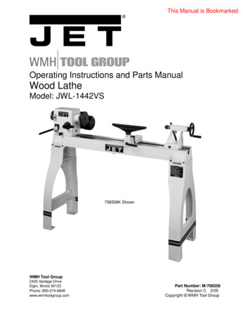
This Manual is BookmarkedOperating Instructions and Parts ManualWood LatheModel: JWL-1442VS708358K ShownWMH Tool Group2420 Vantage DriveElgin, Illinois 60123Phone: 800-274-6848www.wmhtoolgroup.comPart Number: M-708358Revision C 2/05Copyright WMH Tool Group
This manual has been prepared for the owner and operators of a JET JWL-1442VS Wood Lathe. Itspurpose, aside from machine operation, is to promote safety using accepted operating and maintenanceprocedures. To obtain maximum life and efficiency from your wood lathe, and to aid in using the machinesafely, read this manual thoroughly and follow instructions carefully.Warranty and ServiceWMH Tool Group warrants every product it sells. If one of our tools needs service or repair, one of ourAuthorized Repair Stations located throughout the United States can provide quick service or information.In most cases, a WMH Tool Group Repair Station can assist in authorizing repair work, obtaining parts, orperform routine or major maintenance repair on your JET product.For the name of an Authorized Repair Station in your area, please call 1-800-274-6848, or visit our website at www.wmhtoolgroup.com.More InformationRemember, the WMH Tool Group is consistently adding new products to the line. For complete,up-to-date product information, check with your local WMH Tool Group distributor, or visit our web site atwww.wmhtoolgroup.com.WMH Tool Group WarrantyWMH Tool Group makes every effort to assure that its products meet high quality and durability standardsand warrants to the original retail consumer/purchaser of our products that each product be free fromdefects in materials and workmanship as follow: 1 YEAR LIMITED WARRANTY ON ALL PRODUCTSUNLESS SPECIFIED OTHERWISE. This Warranty does not apply to defects due directly or indirectly tomisuse, abuse, negligence or accidents, normal wear-and-tear, repair or alterations outside our facilities,or to a lack of maintenance.WMH TOOL GROUP LIMITS ALL IMPLIED WARRANTIES TO THE PERIOD SPECIFIED ABOVE,BEGINNING FROM THE DATE THE PRODUCT WAS PURCHASED AT RETAIL. EXCEPT AS STATEDHEREIN, ANY IMPLIED WARRANTIES OR MERCHANTABILITY AND FITNESS ARE EXCLUDED.SOME STATES DO NOT ALLOW LIMITATIONS ON HOW LONG THE IMPLIED WARRANTY LASTS, SOTHE ABOVE LIMITATION MAY NOT APPLY TO YOU. IN NO EVENT SHALL THE WMH TOOL GROUPBE LIABLE FOR DEATH, INJURIES TO PERSONS OR PROPERTY, OR FOR INCIDENTAL,CONTINGENT, SPECIAL, OR CONSEQUENTIAL DAMAGES ARISING FROM THE USE OF OURPRODUCTS. SOME STATES DO NOT ALLOW THE EXCLUSION OR LIMITATION OF INCIDENTAL ORCONSEQUENTIAL DAMAGES, SO THE ABOVE LIMITATION OR EXCLUSION MAY NOT APPLY TOYOU.To take advantage of this warranty, the product or part must be returned for examination, postage prepaid,to an Authorized Repair Station designated by our office. Proof of purchase date and an explanation ofthe complaint must accompany the merchandise. If our inspection discloses a defect, we will either repairor replace the product at our discretion, or refund the purchase price if we cannot readily and quicklyprovide a repair or replacement. We will return the repaired product or replacement at WMH Tool Group’sexpense, but if it is determined there is no defect, or that the defect resulted from causes not within thescope of WMH Tool Group’s warranty, then the user must bear the cost of storing and returning theproduct. This warranty gives you specific legal rights; you may also have other rights, which vary fromstate to state.WMH Tool Group sells through distributors only. Members of the WMH Tool Group reserve the right toeffect at any time, without prior notice, those alterations to parts, fittings and accessory equipment, whichthey may deem necessary for any reason whatsoever.2
Warnings1. Read and understand the entire owner’s manual before attempting assembly or operation.2. This wood lathe is designed and intended for use by properly trained and experienced personnelonly. If you are not familiar with the proper and safe operation of a wood lathe, do not use it untilthe proper training and knowledge have been obtained.3. Always wear approved safety glasses/face shields while using this machine.4. Make certain the machine is properly grounded.5. Before operating the machine, remove tie, rings, watches, other jewelry, and roll sleeves up pastthe elbows. Remove all loose clothing and confine long hair. Do not wear gloves.6. Keep the floor around the machine clean and free of scrap material, oil and grease.7. Keep machine guards in place at all times when the machine is in use. If removed formaintenance purposes, use extreme caution and replace the guards immediately.8. Do not over reach. Maintain a balanced stance at all times, so that you do not fall or lean againstblades or other moving parts.9. Make all machine adjustments or maintenance with the machine unplugged from the powersource.10. Use the right tool. Do not force a tool or attachment to do a job that it was not designed to do.11. Replace warning labels if they become obscured or removed.12. Make certain the switch is in the OFF position before connecting the machine to the powersupply.13. Give your work undivided attention. Looking around, carrying on a conversation and "horse-play"are careless acts that can result in serious injury.14. Keep visitors a safe distance from the work area.15. Use recommended accessories; improper accessories may be hazardous.16. Read and understand warnings posted on the machine and in this manual. Failure to comply withall of these warnings may cause serious injury.17. Some dust created by power sanding, sawing, grinding, drilling and other construction activitiescontain chemicals known to cause cancer, birth defects or other reproductive harm. Someexamples of these chemicals are: Lead from lead based paint. Crystalline silica from bricks, cement and other masonry products. Arsenic and chromium from chemically treated lumber.Your risk of exposure varies, depending on how often you do this type of work. To reduce yourexposure to these chemicals: work in a well ventilated area, and work with approved safetyequipment, such as face or dust masks that are specifically designed to filter out microscopicparticles18. Do not operate this lathe while under the influence of drugs, alcohol or any medication.19. Keep tools sharp and clean for safe and best performance. Dull tools can grab in the work and bejerked from the operator s hands causing serious injury.20. Check the condition of the stock to be turned. Make sure it is free of knots, warpage, checkedends, improperly made or cured glue joints and other conditions which can cause it to be thrownout of the lathe.21. Securely fasten spur/live centers to the material being used.22. Check centers and center sockets in the headstock and tailstock to be sure they are free of dirt orrust and oil lightly before inserting centers.23. Test each set-up by revolving the work by hand to insure it clears the tool rest and bed. Check thesetup at the lowest speed before increasing it to the operating speed.24. Use the correct cutting tool for the operation to be performed and keep all tools sharp.25. Use low speeds for roughing and for long or large diameter work. If vibration occurs, stop themachine and correct the cause. See the speed recommendation chart on the next page.3
WarningsSPEED RECOMMENDATIONSDiameter of WorkRoughing RPMGeneral Cutting RPMFinishing RPMUnder 2"1500300030002 to 4"600150023004 to 6"450110015006 to 8"45060011008 to 10"45060085010 to 12"45060085012 to 14"45045060026. When sanding, remove the tool rest from the machine, apply light pressure and use a slow speedto avoid heat build up.27. When turning large diameter pieces, such as bowls, always operate the lathe at low speeds. Seethe speed recommendation chart.28. Do not attempt to engage the spindle lock pin until the spindle has stopped. If leaving themachine area, turn it off and wait until the spindle stops before departing.29. Make no adjustments except speed changes with the spindle rotating and always disconnect themachine from the power source when performing maintenance to avoid accidental starting orelectrical shock.30. Provide for adequate space surrounding work area and non-glare, overhead lighting.31. When stopping the lathe, never grab the part or faceplate to slow it down. Let the work coast to astop.32. Use only JET factory authorized replacement parts and accessories; otherwise, the warranty andguarantee are null and void.33. Do not use this JET wood lathe for other than its intended purpose. If used for other purposes,JET disclaims any real or implied warranty and holds itself harmless from any injury that mayresult from that use.4
Grounding InstructionsThis tool must be grounded while in use to protect the operator from electricshock.In the event of a malfunction or breakdown, grounding provides a path of least resistance for electriccurrent to reduce the risk of electric shock. This tool is equipped with an electric cord having anequipment-grounding conductor and a grounding plug. The plug must be plugged into a matching outletthat is properly installed and grounded in accordance with all local codes and ordinances.Do not modify the plug provided. If it will not fit the outlet, have the proper outlet installed by a qualifiedelectrician.Improper connection of the equipment-grounding conductor can result in a risk of electric shock. Theconductor, with insulation having an outer surface that is green with or without yellow stripes, is theequipment-grounding conductor. If repair or replacement of the electric cord or plug is necessary, do notconnect the equipment-grounding conductor to a live terminal.Check with a qualified electrician or service personnel if the grounding instructions are not completelyunderstood, or if in doubt as to whether the tool is properly grounded. Use only three wire extension cordsthat have three-prong grounding plugs and three-pole receptacles that accept the tool’s plug.Repair or replace a damaged or worn cord immediately.115 Volt OperationAs received from the factory, your sander is ready to run at 115-volt operation. This sander, when wiredfor 115 volts, is intended for use on a circuit that has an outlet and a plug that looks the one illustrated inFigure A. A temporary adapter, which looks like the adapter as illustrated in Figure B, may be used toconnect this plug to a two-pole receptacle, as shown in Figure B if a properly grounded outlet is notavailable. The temporary adapter should only be used until a properly grounded outlet can be installed bya qualified electrician. This adapter is not applicable in Canada. The green colored rigid ear, lug, or tab,extending from the adapter, must be connected to a permanent ground such as a properly groundedoutlet box, as shown in Figure B.The use of an extension cord is not recommended. However, if you must use one make sure yourextension cord is in good condition. Be sure to use one heavy enough to carry the current your machinewill draw. An undersized cord will cause a drop in the line voltage resulting in power loss and overheating.The following table shows the correct size to use depending on the cord length needed and thenameplate ampere rating. If in doubt, use the next heavier gauge. Remember, the smaller the gaugenumber, the heavier the cord.VoltsTotal Length of Cord in Feet120V2550100150AWG12-161412Not RecommendedAmps5
230 Volt OperationIf 230V, single-phase operation is desired, the following instructions must be followed:1. Disconnect the machine from the power source.2. This lathe is supplied with four motor leads that are connected for 115V operation, as shown in FigureA. Reconnect these four motor leads for 230V operation, as shown in Figure B.3. The 115V attachment plug (A), supplied with the lathe, must be replaced with a UL/CSA listed plugsuitable for 230V operation (D). Contact your local Authorized Service Center or qualified electricianfor proper procedures to install the plug. The lathe must comply with all local and national codes afterthe 230-volt plug is installed.4. The lathe with a 230 volt plug should only be connected to an outlet having the same configuration(D). No adapter is available or should be used with the 230-volt plug.Important: In all cases (115 or 230 volts), make certain the receptacle in question is properly grounded.If you are not sure, have a registered electrician check the receptacle.
IntroductionThis manual is provided by JET covering the safe operation and maintenance procedures for a ModelJWL-1442VS Wood Lathe. This manual contains instructions on installation, safety precautions, generaloperating procedures, maintenance instructions and parts breakdown. This machine has been designed andconstructed to provide years of trouble free operation if used in accordance to instructions set forth in thismanual. If there are any questions or comments, please contact either your local supplier or WMH ToolGroup. WMH Tool Group can also be reached at our web site: www.wmhtoolgroup.com.Table of ContentsWarranty. 2Warnings . 3Grounding Instructions. 5115V Operation. 5230V Operation . 6Introduction. 7Table of Contents. 7Specifications . 8Contents of the Shipping Container. 9Unpacking and Cleanup. 9Assembly. 9Stand Legs (optional accessory) . 10Stand Shelf . 10Controls and Features . 10Lathe Tools . 12Mounting Workpiece Between Centers. 13Stock Selection. 14Roughing Out . 14Beads, Coves, “V” Cuts and Parting. 15Sanding and Finishing . 16Face Plate or Bowl Turning . 16Mounting Stock . 16Face Plate or Chuck . 17Wood Selection. 17Checks and Cracks. 17Distortion . 17Tools for Bowl Turning. 17To Shape the Outside of a Bowl . 18To Shape the Interior of a Bowl . 19Sanding and Finishing a Bowl . 19Adjusting the Clamping Mechanism . 20Changing the Belt and Bearings. 20Troubleshooting . 21Part Breakdowns and Parts List . 22Wiring Diagram. 317
SpecificationsJWL-1442VSStock Number. 708358Over Bed .14"Swing Over Tool Rest Base .10"Distance Between Centers.42"Speeds (RPM) . 450, 600, 850, 1100, 1500, 1900, 2300, 3000Spindle Nose .1" x 8 T.P.I.Drive Spindle Through Hole .3/8"Tailstock Spindle Through Hole.3/8”Tailstock Spindle Travel .4”Tool Rest .12”Face Plate .6”Headstock Rotation . 45 , 90 , 135 , 180 , 270 , 360 Headstock Taper .MT-2Tailstock Taper .MT-2Spindle Center to Floor (approx.) .43-1/2”Motor. 1 HP, 1Ph. 115V/230V, Prewired 115VNet Weight (approx.).200 Lbs.Shipping Weight (approx.).215 Lbs.708358K ShownThe above specifications were current at the time this manual was published, but because of our policy ofcontinuous improvement, WMH Tool Group reserves the right to change specifications at any time andwithout prior notice, without incurring obligations.8
WARNINGRead and understand the entire contents ofthis manual before attempting assembly oroperation!Failure to comply may cause serious injury!Contents of the Shipping Containers1. Lathe1. Tailstock1. Headstock1. Face Plate1. Tool Rest Body1. Accessory Package1. Owner’s Manual and Warranty CardAccessory Package Box1. Live Center1. Spur Center1. Index Pin1. Wrench1. Drift Rod1. Tool Rest1. Tool Rest Extension708358K Shown with optional legsUnpacking and Clean-Up1. Remove the shipping container. Do notdiscard any shipping material until the latheis set up and running properly.2. Remove tailstock, tool rest and headstockbefore lifting; see “Adjusting ClampingMechanism” on Page 20 on how to removethe tailstock, headstock or tool rest.3. Remove hex cap bolts from skid bottom andlift the lathe bed, with the help from anotherperson, off the skid and into position.Contents of Accessory Package4. Mount the lathe to a solid workbench or referto the “Stand Legs (optional assembly)”instructions, on page 10, if you havepurchased the stand legs.5. Clean all rust protected surfaces with acleaner degreaser. Clean under theheadstock, tailstock and tool rest body.6. Reinstall headstock, tool rest and tailstockunless you are mounting to optional legs.Assembly1. Secure tool rest (A, Fig. 1) to tool rest body(B, Fig. 1) by tightening handle (C, Fig. 1).Note: For some turning applications, youmay need to assemble the tool restextension between the tool rest body andtool rest.9
Stand Legs (optional accessory)1. At this point the headstock, tailstock and toolrest should be removed. With help fromanother person, lift the lathe bed and placeonto a workbench.2. Angle lathe bed so that stand leg mountingholes are accessible, see Figure 2.3. Thread adjustable feet (A, Fig. 2) into standleg (B, Fig. 2). There is a flat spot on theshaft near the foot that will accommodate awrench. Thread a hex nut (C, Fig. 2) ontoshaft and leave loose for now.4. Mount the leg to lathe bed with four 5/16” flatwashers and four 5/16”-18 x 1-1/2” hexsocket cap screws (D, Fig. 2).5. Repeat for the other leg.6. Adjust the feet so that the lathe rests evenlyon the floor, and tighten the nuts.7. Reinstall headstock, tailstock and tool rest.Stand ShelfYou can make an extra shelf that rests betweenthe legs if you wish, see Figure 3. It will beuseful for storing lathe accessories, or addingsand bags for some extra weight. The two 2x4’sshould be 55-3/4” long. The plywood should beripped into two equal pieces 27-13/16”L x 17”Wso that it can be assembled between the legs.Use screws to attach the plywood to the 2x4supports.Controls & FeaturesE. Headstock Lock Handle: (E, Fig. 4)Locks the head in position. Unlock thehandle to position the head in any locationalong the lathe bed. Tighten handle whenproperly positioned.F. Headstock Indexing Pin: (F, Fig. 4)Turn the knurled knob counter-clockwise tounlock the plunger. Pull the knob out torelease the headstock. Unlock theheadstock-locking handle and rotate theheadstock. Turn knurled knob clockwise untilit stops to lock plunger.10
G. Headstock Spindle Lock: (G, Fig. 5)Push in pin to keep the spindle from turning.CAUTION!Never press the headstock spindle lock whilethe spindle is turning!H. Headstock On/Off Switch: (H, Fig.5)Flip the switch up to turn “ON” the lathe. Flipthe switch down to turn the lathe “OFF”.I.Headstock On/Off Switch Key: Removekey (I, Fig. 5) when in the “OFF” position.The switch will not work until key isreinstalled.J.Headstock Speed Selector: (J, Fig. 5)Place handle directly above the desiredRPM speed. Pull handle out and move tothe desired speed, see Figure 6.CAUTION!Only change speeds while the spindle isturning!K. Headstock Faceplate: (K, Fig. 7)Used for turning bowls. There are a numberof screw holes for mounting the workpiece.Thread the faceplate onto the spindle in aclockwise direction, and tighten twosetscrews. Remove the faceplate byloosening two setscrews. Push in headstockspindle lock and use the provided wrench onfaceplate flats.L. Headstock Spur Center: (L, Fig. 7)Used for turning between centers. Spindletaper is MT-2. Remove spur center byinserting drift rod through the opposite endof the spindle and knocking spur center out.M. Headstock Indexing Hole: (M, Fig. 7)Thread indexing pin into the indexing holemaking sure that it locates in the spindlehole. There are 12 holes in the spindle 30 apart. Three holes in the headstock castingaccept the indexing pin. These holes are 20 apart. The combination of holes will allowyou to mark your workpiece for evenlyspaced features.CAUTION!Never start the lathe with the index pinengaged in the spindle!11
N. Tool Rest Body Lock Handle: (N, Fig. 8)Locks the tool rest body in position. Unlockhandle to position the tool rest in anylocation along lathe bed. Tighten handlewhen properly positioned.O. Tool Rest Lock Handle: (O, Fig. 8)Locks the tool rest in position. Unlock thehandle to position tool rest at a specificangle, or height. Tighten handle whenproperly positioned.P. Tailstock Lock Handle: (P, Fig. 9)Locks the tailstock in position. Unlockhandle to position the tool rest in anylocation along lathe bed. Tighten handlewhen properly positioned.Q. Tailstock Quill Lock Handle: (Q, Fig. 9)Locks the tailstock quill in position. Unlockhandle to position the quill. Tighten handlewhen properly positioned.R. Tailstock Quill Handwheel: (R, Fig. 9)Turn the handwheel to position the quill. Thetailstock quill lock handle must be loose toposition quill.S. Tailstock Live Center: (S, Fig. 9)Used for turning between centers. Quilltaper is MT-2. Remove live center byretracting the quill until live center loosens.Lathe ToolsIf possible, select only high quality, high speedsteel turning tools with long handles. As onebecomes proficient in turning, a variety ofspecialty tools for specific applications can beacquired. The following tools provide the basicsfor most woodturning projects. See your JETdistributor for a wide variety of JET woodturningtools.Roughing Gouge — used for rapidly cut rawwood into round stock, see Figure 10.Deep Fluted Bowl Gouge — used for turningbowls and plates, see Figure 10.Spindle Gouge — used for turning beads,coves and other details, see Figure 10.Spear — fine scraping and delicate operations,such as the forming of beads, parallel groovesand shallow vees, etc, see Figure 10.12
Lathe Tools (continued)5. Move tool rest into position. It should beparallel to workpiece, approximately at thecenterline, and approximately 1/8" from theclosest part of the workpiece. Lock tool restbody and tool rest in place.Skew — used to make vees, beads, etc., seeFigure 11.Square Scraper — used for diameter scrapingand featureless scraping, etc, see Figure 11.6. Rotate workpiece by hand to check forproper clearance from tool rest. Note: Youmay want to trim off the corners of a squareworkpiece to make turning a little easier.Large Domed Scraper — used to reduce ridgeson the interior of bowls, round edges of bowls,etc, see Figure 11.7. Start lathe at lowest speed and bring it up tothe appropriate RPM for the size of stock,see Figure 6 page 11.Parting Tool — used to cut directly into thematerial, or to make a cut off. Also used forscraping and to set diameters, see Figure 11.The position of the tool rest can be varied to suitthe work and operator. After you becomeexperienced with setting tool rest changing theposition will become second nature for theworkpiece and comfort of the user.For safety and best performance, keep toolssharp. If a tool stops cutting, or requiresexcessive pressure to make a cut, it needs to besharpened. A number of brand name sharpeningjigs and fixtures are available, however, awoodturner should learn to sharpen toolsfreehand.Mounting Workpiece Between CentersSpindle turning takes place between the centersof the lathe. It requires a spur center in theheadstock and a live center in the tailstock.1. With a ruler locate and mark the center oneach end by going corner to corner, seeFigure 12. Accuracy is not critical on fullrounds but extremely important on stockwhere square sections are to remain. Put adimple in each end of the stock with an awlor nail.2. Extremely hard woods may require kerfs cutinto the spur drive end of stock, see Figure12. You may need to drive the spur centerinto the stock with a wood mallet. Note:Never drive stock onto spur while it ismounted in the lathe spindle.3. Install workpiece by inserting the attachedspur center into the spindle taper on theheadstock.4. Bring tailstock into position, lock it to thebed, and advance quill with the handwheelin order to seat the live center into the
2. This wood lathe is designed and intended for use by properly trained and experienced personnel only. If you are not familiar with the proper and safe operation of a wood lathe, do not use it until the proper training and knowledge have been obtained. 3. Always wear approved

