Transcription
RWUXI KIPOR POWER CO., LTD.DIGITAL DIESELGENERATOR SETID6000
PREFACEThank you for purchasing our generators.This manual covers operation and maintenance of ID6000 generator.All information in this publication is based on the latest product information available atthe time of approval for printing.We reserve the right to make changes at any time without notice and without incurringany obligation.No part of this publication may be reproduced without written permission.This manual should be considered a permanent part of the generator and should bereserved with it if it is resold.Pay special attention to statements preceded by the following words:DANGERFailure to properly follow these precautions can result inserious injury or DEATH!WARNINGFailure to properly follow these precautions can result inproperty damage, serious injury or DEATH!CAUTIONThe generators are designed to give safe and dependableservice if operated according to instructions. Failure to do socould result in personal injury or equipment damage.If a problem should arise, or if you have any questions about the generator, consult anauthorized dealer.WARNINGIndicates a possibility of personal injury or equipment damageif instructions are not followed.Read and understand the Owner's Manual before operatingthe generator.Operate only in well ventilated areas. Exhaust gas containspoisonous carbon monoxide, and can be deadly.Always stop engine before refueling. Wait 5 minutes beforerestarting.Check for spilled fuel or leaks. Clean and/or repair before use.Keep any sources of ignition away from fuel tank at all times.
CONTENTS1. SAFETY INSTRUCTIONS12. SAFETY LABEL LOCATIONS33. COMPONENT IDENTIFICATION44. PRE-OPERATION CHECK85. STARTING THE ENGINE116. GENERATOR USE137. STOPPING THE ENGINE178. MAINTENANCE189. TRANSPORTING/STORAGE2210. TROUBLESHOOTING2311. SPECIFICATIONS2412. ELECTRICAL WIRING DIAGRAM2513. APPENDIX26
2. The choice of the electric cableThe choice of the electric cable depends on the allowable current of the cableand the distance between the load and the generator. And the cable sectionshould be big enough.If the current in the cable is bigger than the allowable current, it will become overhot and the cable will be burnt. If the cable is long and thin, the input voltage ofthe electric appliance will be not enough, causing that the generator doesn't start.In the following formula, you can calculate the value of the potential "e".Potential (v) 1Length58Section areaCurrent (A)1. SAFETY INSTRUCTIONWARNING3The relations among of the allowable current, and length, section of the Insulatingcable (single core, multi-core) are as follow:(Presume that the use voltage is 220V and the potential is below 10V.WARNINGAmbient temperature25Single coreCurrent capacity(25 )(A)VoltageDropmv/MThree coresCurrent capacity(25 )(A)VoltageDropmv/MFour coresCurrent capacity(25 )(A)VoltageDropmv/MNo.Coppercables 06600.253814800.21400495490WARNINGThe generators are designed to give safe and dependableservice if operated according to instructions.Read and understand the Owner's Manual before operatingthe generator. Failure to do so could result in personal injuryor equipment damage.Please use light diese. Gasoline and pafaffin is not allowedto useExhaust gas contains poisonous carbon monoxide. Neverrun the generator in an enclosed area. Be sure to provideadequate ventilation.Generator should be earthed with a wire to avoid electricshockThe muffler becomes very hot during operation andremains hot for a while after stopping the engine.Be careful not to touch the muffler while it is hot.Let the engine cool before storing the generator indoors.The engine exhaust system will be heated during operationand remain hot immediately after stopping the engine.Toprevent scalding, pay attention to the warning marks attachedto the generator.Battery charge should be carried out in the place with goodventilation. Smoke and spark is forbidden.Note: The variation of temperature and the laying of cables will influence the current capacityof cables, the table above is just used for reference.--- -
Ensure safe operationWARNINGGasoline is extremely flammable and explosive undercertain conditions. Refuel in a well ventilated area withthe engine stopped.Keep away from cigarette, smoke and sparks whenrefueling the generator, Always refuel in a well-ventilatedlocation.Wipe up spilled gasoline at once.13. APPENDIX1. Modified coefficient table of ambient condition powerThe conditions of generator rated output:Altitude: 0 mWARNINGWARNINGConnections for standby power to a building'selectrical system must be made by a qualified electricianand must comply with all applicable laws and electricalcodes. Improper connections can allow electrical currentfrom the generator to back feed into the utility lines. Suchback feed may electrocute utility company workers orothers who contact the lines during a power outage, andwhen utility power is restored, the generator mayexplode, burn, or cause fires in the building's electricalsystem.Always make a pre-operation inspection before youstart the engine to prevent an accident or equipmentdamage.Place the generator at least 1m away from buildingsor other equipment during operation.Operate the generator on a level surface. if thegenerator is tiled, fuel spillage may result.Know how to stop the generator quickly andunderstand operation of all the controls. Never permitanyone to operate the generator without properinstructions.Keep children and pets away from the generatorwhen it is in operation.The generator is a potential source of electricalshocks when misused; do not operate with wet hands.Do not operate the generator in rain or snow and donot let it get wet to avoid electric shock.Ambient temperature: 25Relative humidity: 30%Ambient modified coefficient: C (Relative humidity 30%)Ambient temperature 0.480.46Note: When the relative humidity is 60%, the modified coefficient is C-0.01When the relative humidity is 80%, the modified coefficient is C-0.02When the relative humidity is 90%, the modified coefficient is C-0.03When the relative humidity is 100%, the modified coefficient is C-0.04Counting example:When the rated power of generator is PN 5KW, altitude is 1000m, ambienttemperature is 35P PN- -(C-0.02) 5, relative humidity is 80%, the rated power of generator is:(0.82-0.02) 4KW--
12.2 Single voltage2. SAFETY LABEL LOCATIONThese lables warn you potential hazards that can cause serious injury. Read the labelsand safety notes and precautions described in manual carefully.Fuel use stickerHook stickerLow oil pressurewarning stickerOperation warning stickerBattery power warningGenerator parameter stickerFrequency stickerOutdoor use stickerFuel warning stickerModel stickerHigh temperature sticker--- -
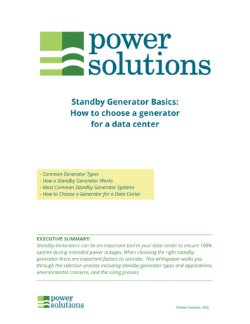
3. COMPONENT IDENTIFICATION12. ELECTRIC DIAGRAM1. Profile drawing12.1 Dual voltageBoomFuel fillerMuffler exhaust pipeMaintenance doorStarter motorCover plate of fuel fillerHandleDiesel filterrPanelModuleBatteryAir filterSide doorAir filter sticker1. Battery maintenancecover plate2. Battery fixing belt3. BatterySeries NoBattery maintenance sticker- ---
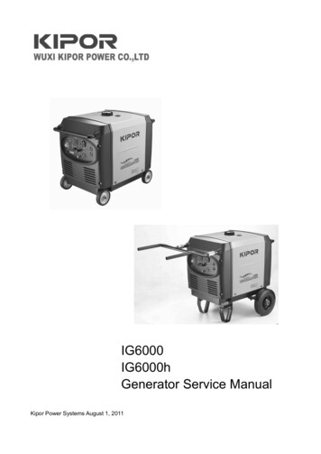
2. Electric system11. SPECIFICATIONModelRated frequency (Hz)ID60005060Rated output (kVA)5Max. output (kVA)5.5Rated voltage (V)115/230Rated current (A)43.5/21.7120/24041.7/20.81700-3300Rated rotation speed (r/min)AlternatorModelKD70Motor type/Converter type Multi-pole permanent magnet motor /IGBT digital converterLoop typeSingle phase three loopsPower factor(COS )1Insulation gradeFModelCylinder typeKD186FGETiVertical single cylinder, four stroke, air cooled, direct e speed range should be according with the AC inverter total output power:Rated low speedzero loadRated high speedRated max. output power7543619.6 1Compression ratioRated power6.3/3600Pressure splashLub. modeLubricantAbove CD grade or SAE10W 30Lubricant capacity3. Control panel15W 401.65Output indicator lamp (Green)Starting systemElectric starterBattery capacity12V 36AhFuel type2.1 Elements and functionDigital diesel generator consists of alternator, AC inverter, electric regulator, electriccontrol system, harness and output/input units.The functions of each units are listed as follow:2.2 Alternator:Alternator adopts permanent magnet generator, consisting of stator, rotor and shell. Therotor without bearings adopts one piece design with engine Fixed at one side ofcrankshaft , brushless and natural draft. The stator adopts multi-pole and multi-voltagewindings. It is rotates with the crankshaft to outuput three phase AC. The generatorfeatures small volume, simple structure and high efficiency.2.3 AC inverter:AC voltage output by alternator is rectified and inverted for AC loads. AC invertermodule includes protection for overload, over voltage, over frequency, over heat etc.2.4 Electric regulator:Electric regulator features convenient installation, rapid response, good regulation andsafety.It can automatically regulate the engine speed depending on the loads to ensure thebest economicsDiesel: 0 (summer), 10Fuel consumption(winter), 35340Fuel tank capacity14.5Continuous running time (hr) (at rated output)6.562-69Noise (zero load- full load)875Dimension (LxXWXH)530168Net weight750Overload alarm lamp(Red)Low oil level alarm lamp(Red)(chilliness)Over speed alarm lamp (Red)1. Socket2. Breaker3. LCD monitor4. Lamp5. Electric lock (start switch)6. Conjoined socket7. Socket8. Earthing end9. Reset switch10. Energy saving switchDual voltage panelSilentStructure--- -
10. TROUBLE SHOOTINGOutput indicator lamp (Green)Overload alarm lamp (Red)Low oil level alarm lamp (Red)Over speed alarm lamp (Red)1. Socket2. Breaker3. LCD monitor4. Lamp5. Energy saving switch6. Electric lock (start switch)7. Earthing end8. Socket9. Reset switchSingle voltage panel10. ATS option switchWhen the engine will not start:Is there fuel in the tank?NoRefill the fuel tank.YesIs there enough oil in the engine?NoAdd the recommended oil.Yes3.1. LCD instruction:Is the battery voltage 12 to 15V?NoReplace or charge the batteryKeyScreenYesTake the generator to an authorized dealer.The engine fails to run with load:3.1.1 Instructions of dual voltage connectorIs the output indicator lamp onNoTake the generator to an authorized dealerNoTurn on the breaker.YesItemFunctionItemFunctionItem9B phase current transformer input10B phase current transformer inputFunction1A phase AC voltage input52B phase AC voltage input65 6 out external switch,Series connection when closedParallel connection when open3A phase AC voltage input7A phase current transformer input11External battery GND4B phase AC voltage input8A phase current transformer input12External battery 12VIs the AC breaker switched on?YesIs the overload indicator lamp on?Is the electric appliance in good condition?FunctionItemFunctionItem1AC voltage input4Relay control signal output ( 12v)7External battery GND2AC voltage input5Current transformer input8External battery 12V3Current transformer input6Relay control signal output (GND)9- -Lower down the load or replace the generator for a larger oneYes3.1.2 Instructions of single voltage connectorItemYesFunctionYesReplace or charge the electric applianceYesTake the generator to an authorized dealer.--
9. TRANSPORTING/STORAGEl spillage when transporting or during temporary storage, the genera-tor should besecured upright in its normal operating position, When transporting the generator:WARNINGDo not overfill the tank (there should be no fuel in the fillerneck)Do not operate the generator while it is on a vehicle. Takethe generator off the vehicle and use it in a well ventilatedplace.Avoid a place exposed to direct sunlight when putting thegenerator on a vehicle. If the generator is left in an enclosedvehicle for many hours, high temperature in-side the vehiclecould cause fuel to vaporize resulting in a possible explosion.?Do not drive on a rough road for an extended period with thegenerator on board, if you must transport the generator on arough road, drain the fuel from the generator beforehand.Before long while storag, the following items should be done:(1) Run the generator for 5 minutes without any load.(2) Drainage the oil and refill the new oil.(3) Drainage the fuel to a clean container and clean the fuel tank.(4) Clean the dirty in generator. Seal the generator with a plastic cover for safekeepingin dry place.WARNINGFuel is explosive and flammable. Smoke, fire and spark areforbidden.1. For example LCD-230V1---Genset output voltage (V); 2---Genset current with load (A);3---Genset frequency (Hz);4---Genset running timeCode5---Battery voltage.Shift the parameters by the button2. LCD-120V / 240V(1) Output in parallel:1---output voltage;4---output current;7---Running time;8---Battery voltage;(2) Output in series:1---Sum of A, B phase voltage;2---A phase voltage;4---A phase current;5---B phase current;7---Running time;8---Battery voltage;ParameterKey6---output frequency;(2 3 5 are shielded)3---B phase voltage;6---output frequency;3.1.3 Maintenance information1. Maintenance will be reminded after specific running time. LCD lamp twinkles and thecodes will be displayed. If there is many codes, they may be displayed in turns at aninterval of 3 seconds if there is many codes.ItemMaintenance informationCode1OilSV 12Oil filterSV 23Air filterSV 34Nozzle pumpSV 45Valve clearanceSV 56Tank and filterSV 62. Press the button to read the parameters. Release the key for 2 seconds to have themaintenanceRemind.3. Press the button for 5 seconds to clear the maintenance information.3.2 Instruction of energy saving switch:Energy saving switchWhen Energy saving switch locates the side of "OFF" the speed of engine varieswhen output power varies. Power increases while speed increases. Engine will rununder the low speed without any load; the total machine will work in perfect economicstate.When Energy saving switch locates the side of "ON" Engine will run under the max.speed. Inverter module reaches max. power. This mode must be used during suddenload and unload.--- -
a. Open the left door, loose the hoop and remove the diesel filterb. Replace the diesel filterc. Reinstall the filter element. Fix the hoop and close the left door.4. PRE-OPERATION CHECKBe sure to check the generator on a level surface with theengine stoppedWARNING4. Pump maintenance:Do not dismantle the pump randomly. Please contact KIPOR dealer if special tools arerequired for pump replace and clean.1. Check the engine oil levelUsing nondetergent oil or 2-stroke engine oil could shortenthe engine's service life.WARNINGAir filter sticker1. battery maintenancecover plate2. battery fixing belt3. batteryUse a high-detergent, premium quality 4-stroke engine oil. certified to meet CC or CDgrade SAE10W-30 oil is recommended.Select the appropriate viscosity of oil according to the ambient temperature.Viscosity---Ambient temperatureSingle gradeAmbienttemperature -30SAE4050SAE20 20WSAE10W-25-20-15-10SAE30-5051015202530Genset codeSAE10W/30Multi gradeSAE15W/40Battery maintenance stickerSAE5W/20SAE5W/30SAE Viscosity grade tableOpen the left door, Loose the cap and wipe the dipstick with a clean rag. Check the oillevel by inserting the dipstick in the filler hole after fastened.If the oil level is below the end of the dipstick, refill the recommended oil up to the top ofthe oil filler neck.WARNINGCAUTION5. Battery maintenancea. Unscrew the bolts on cover plate, remove the cover plateb. Remove the fixing beltc. Replace the battery and fasten the fixing belt, install the cover plate, fasten the boltsand close the side door.Running the engine with insufficient oil can cause seriousengine damage.The Low Oil Alarm System will automatically stop theengine before the oil level falls below the safe limit. However,to avoid the inconvenience of an unexpected shutdown, it isstill advisable to visually inspect the oil level regularly- ---
For enviroment protection, we recommend that the wasteoil should be kept in seal containers and send to the repairagency and recycling center. Do not drain the oil to the groundor rubbish.CAUTIONDipstickUpper levelOil filler2. AIR CLEANER SERVICELowerlevelA dirty air cleaner will restrict air flow to the engine cylinder. To prevent it, service the aircleaner regularly. Service more frequently when operating the generator in extremelydusty areas.Do not use gasoline or low flash point solvents for cleaning.They are flammable and explosive under certain conditions.Please replace the filter element if power is reduced orexhaust smoke color is abnormal.Do not run generator without air cleaner for causing engineaccelerated wear.CAUTION2. Check the fuel levela. Open the side door.b. Loose the nut on filter cap, disconnect the cap.c. Take out the air filterd. Clean the dirty on filter element, but detergent is not allowed.e. Re-install the filter element, lock the cap and close the side door.Use automotive light diesel.If the fuel level is low, refuel the fuel tank until the level increased to the specified mark.Never use an oil/diesel mixture or dirty diesel.Avoid getting dirt, dust or water in the fuel tank.After refueling, tighten the oil rule seurely.WARNINGAir filter bottom shellAir filter bottom sealAir filter elementSeal ring of air filter shellAir filter capThumb nutDiesel is extremely flammable and is explosive undercertain conditions.Refuel in a well-ventilated area with the engine stopped. Donot smoke or allow flames or sparks in the area where theengine is refueled or where fuel is stored.Do not overfill the fuel tank (there should be no fuel abovethe upper limit mark). After refueling, make sure the tank cap isclosed properly and securely.Be careful not to spill fuel when refueling. Spilled fuel or fuelvapor may ignite, If any fuel is spilled, make sure the area isdry before starting the engine.Avoid repeated or prolonged contact with skin or breathingof vapor. KEEP OUT OF REACH OF CHILDREN3. Fuel filter maintenanceA dirty fuel filter will restrict fuel flow to pump. To prevent it, service the fuel filterregularly.--- -
a. Open side door, unscrew the dipstick.b. Drain the dirty oil to a containerCover plate of fuel fillerTank capTank capUpper levelOil level indicatorFilter netc. Refill the recommended oil to the oil filler level and check itd. screw the dipstick and close the side doorOil capacity: KD186FGETiEngine: 1.65 L.Oil dipstick3. Check the air cleanerCheck the air cleaner element to be sure it is clean and in good condition.Open the right door, loose the nut and remove the cap to check the filter element.Clean or replace the element if necessary.Oil drainage holeOil drainage boltAir filter bottom shellAir filter bottom sealAir filter elementSeal ring of air filter shellDipstickUpper limitAir filter capOil fillerThumb nutLowerlimitCAUTIONNever run the engine without the air cleaner. Rapid enginewear will result from contaminants.¡ 4. Check fuel filterCheck the fuel filter to be sure it is clean and in good condition. Open the left door,check the filter element. Clean or replace the element if necessary.----
8. MAINTENANCE5. STARTING THE GENERATORThe purpose of the maintenance and adjustment schedule is to keep the generator inthe best operating condition.1. Before starting the genset, disconnect the load from the DC terminals.Ensure the breaker is kept at "OFF"Shut off the engine before performing any maintenance. Ifthe engine must be run, make sure the area is well ventilated.The exhaust contains poisonous carbon monoxide gas.WARNINGBreakerUse genuine our parts or their equivalent. The use ofreplacement parts which are not of equivalent qual-ity maydamage the generator.CAUTIONMaintenance ScheduleItemRegular service periodFirstmonthor20 hoursEachuseEvery 3monthsor50 hoursEvery 6monthsor 100hoursEveryyearor 200hours(after second time)(after second time)2. Turn the switch to the start position, then generator begins to preheat automatically.(Replace)Loose it after all lamps lit, the switch returns to "ON", which means generator startssuccessfully. For start failure, please restart the generator after waiting for 10 minutes.CheckOilReplaceOil filterAir filterNozzle pump(first time)Check and replaceCheck(2)Clean(3)Clean adjust(3)Valve clearance Check adjustTank and filterClean or replaceOil circuitCheckEvery 2 years(replace if necessary)(3)NOTE: (1) "O" means normal maintenance interval(2) "O(2)" means generator used in dirty area. Please shorten the maintenance interval(3) "O(3)" means maintenance and repair should taken by KIPOR dealer unlessprofessionals are available. Please refer to the maintenance manual.1. CHANGING OILRun generator for 3heated.WARNING5 minutes and stop it. Drain the oil quickly when the generator isEnsure the generator is stopped before drainage.----
3. Turn the breaker to "ON", connect with the loads.7. STOPPING THE ENGINETo stop the engine in an emergency, turn the engine switch to the OFF position.BreakerIN NORMAL USE:1. Turn the breaker to "OFF".Breaker4. Instruction:Engine can keep the rated power in standard ambient. If the ambient varies, pleaserefer to GB/T6072.1 for power and fuel consumption.2. Switch off the connected equipment and pull the inserted plug.3.Turn the engine switch to the OFF position.Turn the generator start switch to "OFF", cut off the batterypower for a long while storage----
WARNINGBattery is easily flammable and vaporized. Keep away fromthe spark and fire. Charge the battery in the place with goodventilation.Electrolyte contains sulfuric acid which may burn the skinand eyes. Please wear mask and protective clothes.(1) If the electrolyte splashes to skin, wash off by water atonce(2) If the electrolyte splashes to eyes, please wash it by waterat least 15 minutes, then go to hospital quickly.If electrolyte is swallowed, please drink much water and milk,magnesia or vegetable oil and go to hospital.Please charge in the place out of the reach of children.6. GENERATOR USEWARNINGTo prevent electrical shock from faulty appliances, thegenerator should be earthed. Connect a length of heavy wirebetween the generator's earth terminal and an external groundsource.6.3 Overload DC circuit may result in the protector tripping. In this condition,please disconnect DC load and press the reset key on control panel.ONConnections for standby power to a building's electricalsystem must be made by a qualified electrician and mustcomply with all applicable laws and electrical codes. Improperconnections can allow electrical current from the generator tobackfeed into the utility lines. Such backfeed may electrocuteutility company workers or others who contact the lines duringa power outage, and when utility power is restored, thegenerator may explode, burn, or cause fires in the building'selectrical system.OFFWARNING6.4 For electrical equipment, Large current will be generated when themotor drving system starts.--Do not overload.Do not exceed the current limit specified for any onereceptacle.Do not connect the generator to a household circuit. Thiscould cause the damage to the generator or to electricalappliances in the house.Do not modify or use the generator for other purposes thanit is intended for. Also observe the following when using thegenerator.A. Do not connect generators in parallel.B. Do not connect an extension to the exhaust pipe.When an extension cable is required, be sure to use atough rubber sheathed flexible cable.Limit length of extension cables: 60 m for cables if 1.5mm2 100m for cables of larger than 2.5 mm2 and the currentcapacity within 5A/ mm2.--
CAUTIONKeep the generator away from other electric cables or wiressuch as commercial power supply lines.DC receptacle is availabe for DC powerThe total power shouldn't exceed the sum of AC and DCpower if AC and DC power are used at same time.For most equipment, the motor needs the power higherthan rated value for startingIf red lamp is on, stop the engine and find out the reason.Check the load condition before they are connected to theWARNINGgeneratorRed and green lamp may be on at the same time duringgeneartor starting. If red lamp is off after 4 seconds, it meansthe generator is in normal; if the red lamp still keeps on,please contact KIPOR dealer.6.1 AC applications1. Start the engine and make sure the output indicator light (green) comes on.2. Confirm that the appliance to be used is switched off, and plug in the appliance.WARNINGOverload indicator lamp (red) is on for a long while,generator may be damaged; although overload indicator lampis on a short while, the generator service lift may still beshortened.Be sure that all appliances are in good working orderbefore connecting them to the generator. If an appliancebegins to operate abnormally, becomes sluggish, or stopssuddenly, turn off the generator engine switch immediately.Then disconnect the appliance, and examine it for signs ofmalfunction.3. Low oil level alarmThis system is designed for protecting engine due to lackage of oil. It will stop theengine automatically if the oil level of crankshaft box is below the safe value. (generatorswitch still keeps in "ON" position). If customers restart the engine, the alarm lamp(red)will twinkle, and the engine can't be started. Please add the oil in this condition.Ouput indicator lamp (green)Overload alarm lamp(red)Low oil level alarm lamp(red)Over speed alarm lamp (red)4. Over speed alarmGenerator will stop at once and alarm lamp will be on if engin is over speed for (0.5seconds).Ouput indicator lamp (green)6.2 Output and Overload IndicatorsOverload alarm lamp(red)1. In normal condition, ouput indicator lamp (green) is onLow oil level alarm lamp(red)Ouput indicator lamp (green)3Over speed alarm lamp (red)Overload alarm lamp(red)Low oil level alarm lamp(red)WARNINGOver speed alarm lamp (red)2. If generator overloads (more than 5.5kVA), or loads have short circuitouputindicator lamp (green) will be off while overload lamp(red) will be on. At this time thecurrent to loads will be cut offTo avoid spark, please connect the charge cable togenerator first, then connect the battery. During dismantling,remove the battery first.Do not confuse the and - pole, or the generator andbattery will be damaged.Ouput indicator lamp (green)Overload alarm lamp(red)Low oil level alarm lamp(red)DANGEROver speed alarm lamp (red)--For car battery charge application, disconnect the batteryearth cable before connecting to the generator. Duringdismantling, disconnect the charge cable before earthing,which will prevent the short circuit and spark.Do not start the car if the genetor sill keep connecting withthe car.--
WUXI KIPOR POWER CO., LTD. R . GENERATOR SET. Thank you for purchasing our generators. This manual covers operation and maintenance of ID6000 generator. All information in this publication is based on the latest product information available at . Clean and/or repair before use. Keep any