Transcription
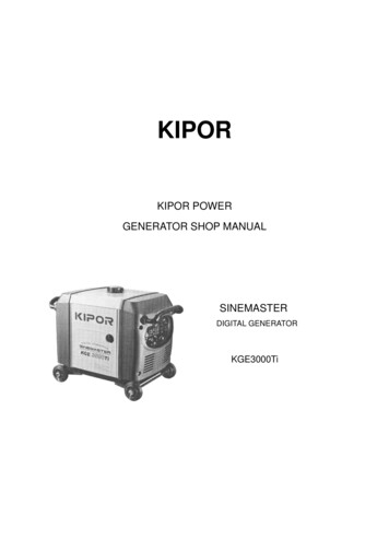
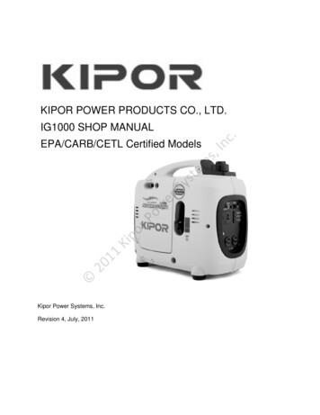
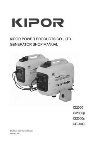
KIPOR POWER PRODUCTS CO., LTD.GENERATOR SHOP MANUALIG2000IG2000pIG2000sCG2000The Coast Distribution SystemJanuary, 2007
PREFACEThis manual covers the construction, function and servicing procedure of the KIPOR IG2000, IG2000Pand CG2000 generators manufactured for the Coast Distribution System.Careful observance of the instructions contained in this manual will result in safe and qualitymaintenance and repair work.All information, illustrations, directions and specifications included in this publication are based on thelatest product information available at the time of approval for printing.KIPOR POWER CO., LTD, reserves the right to make changes without incurring any obligation whatever.No part of this publication may be reproduced without written permission.ii
CONTENTS1. SPECIFICATIONS/WIRING DIAGRAMS . 12. SERVICE INFORMATION . 63. TROUBLESHOOTING.114. MAINTENANCE. 215. MUFFLER . 316. AIR FILTER/CARBURETOR. 327. CONTROL PANEL. 368. SPOTLIGHT . 439. HOUSING . 4410. FUEL TANK . 4611. FAN SHIELD/ENGINE PLATE. 4712. CG CONVERTER MODULE . 4813. GUIDE PLATE . 4914. RECOIL STARTER. 5015. IGNITION COIL AND RECTIFIER. 5216. GENERATOR/TRIGGER . 5417. CYLINDER HEAD/ROCKER ARM ASSEMBLY . 5618. CRANKCASE COVER/CAMSHAFT DRIVING CHAIN . 5819. CRANKSHAFT/PISTON . 65iii
1. SPECIFICATIONS1.1 SPECIFICATIONSDimensions and weightsModelIG2000/IG2000p/CG2000IG2000sOverall Length in (mm)20.5 (520)26.2 (665)Overall Width in (mm)11.8 (300)11.8 (300)Overall Height in (mm)16.7 (425)16.7 (425)Net Weight lbs (kg)48.4 (22)52.8 (24)EngineModelKG158Type4-stroke,OVC, single cylinder, Gasoline engineDisplacement cu in (cc)(105)Horsepower/RPM2.2/4500Compression ratio8.5:1Cooling systemForced air-cooledIgnition systemT.C.IIgnition timing27 B.T.D.CSpark plugUR5CarburetorFloat type, Horizontal, butterfly valve typeAir cleanerSemi-dry typeGovernorElectronically controlledLubrication systemForced splashOil capacity qt (L).35 (0.4)Starting systemRecoil starterFuel usedAutomotive unleaded gasoline 87 octaneGeneratorModelKD20 Inverter/KM20 ConverterGenerator typeMulti pole rotation typeGenerator structureSelf-ventilation drip-proof typeExcitationSelf-excitation (Magnet type)Voltage regulation systemPulse width modulation)PhaseThree phaseRotating directionClockwise (Viewed from the generator)Frequency regulationAC-DC-AC conversion (Inverter type)AC-AC conversion (Converter type)1
ModelAllMaximum output AC2.0KVARated output AC1.6KVARated output DC100WRated frequency60HZRated voltage AC120VRated voltage DC12VRated current AC13.3ARated current DC8.3APower factorVoltage variation rate1.0Momentary10% maxAverage1.5% maxAverage time3 sec maxVoltage stability 1%Frequency variation rate Momentary1% maxAverage1% maxAverage time1 sec maxFrequency stability 0.1%Insulation resistance10 0ȍ minAC circuit protector17.9A @120VDC circuit protector10AFuel tank capacity gal (L).9 (3.5 )Operating hours (at rated load)4Noise level NL-FL @23’ (7 m)54-592
1.2 WIRING DIAGRAMSIG2000/IG2000s3
IG2000pc. CG2000/CG2000s4
CG2000IIIIIIIIIIIIIIIIIAC Module5
2. Service Information2.1 The importance of proper servicingProper servicing is essential to the safety of the operator and the reliability of the generator.Any error or oversight made by the technician while servicing can easily result in faultyoperation and/or damage to the equipment or injury to the operator. WarningImproper servicing can cause an unsafe condition that can lead to serious injury or death.Follow the procedures and precautions in this shop manual carefully.Some of the most important precautions are stated below.2.2 Important safety precautionsBe sure you have a clear understanding of all basic shop safety practices and that you arewearing appropriate clothing and safety equipment. When performing maintenance orrepairs, be especially careful of the following:·Read the instructions before you begin, and be sure you have the tools and skillsrequired to perform the tasks safely.·Be sure that the engine is off before you begin any maintenance or repairs. This willreduce the possibility of several hazards:- Carbon monoxide poisoning from engine exhaust.- Burns from hot parts.- Injury from moving parts.·Do not run the engine unless the instructions tell you to do so. Keep your handsand clothing away from rotating parts.·To reduce the possibility of fire or explosion, exercise extreme caution whenworking around gasoline. Use only a nonflammable solvent, not gasoline, to cleanparts. Keep cigarettes, sparks and flames away from all fuel-related parts.6
2.3 Service rules·Use genuine KIPOR or KIPOR-recommended parts and lubricants or theirequivalents. Parts that do not meet Kipor’s design specifications may damage theengine.·Use the special tools designed for the product.·Always install new gaskets, O-rings, etc. when reassembling components.·Clean parts in cleaning solvent upon disassembly. Lubricate any sliding surfacesbefore reassembly. After reassembly, check all parts for proper installation andoperation.·Many screws used in this machine are self-tapping. Be aware that cross-threading orover tightening these screws will strip the threads and ruin the hole.·Use only metric tools when servicing this engine. Metric bolts, nuts and screws arenot interchangeable with non metric fasteners. The use of incorrect tools andfasteners will damage the engine.2.4Electrical precautions·Hold the connector body to disconnect the connector. Do not disconnect by pullingthe wire harness. To disconnect the locking connector, be sure to unlock first, andthen disconnect.·Check the connector terminals for bend, excessive extrusion, missing terminals, orother abnormalities before connecting the connector.·To connect, insert the connector as far as it goes. If the connector is a locking type,be sure that it is locked securely.·Check the connector cover for breakage and check whether the connector femaleterminal is not opened excessively. Then, connect the connector securely. Check theconnector terminal for rust. Remove the rust using an emery paper or equivalentmaterial before connecting the connector.·Set the harness clips in the specified places of the frame securely, and secure thewire harnesses.·Clamp the cables securely.·Clamp the wire harnesses securely so that they do not interfere with the rotatingparts, moving parts and hot parts.7
·Route and connect the wire harnesses properly. Be sure that the harnesses are notslack, twisted or pulled overly taut.·Route the wire harnesses properly so that they do not contact sharp edges andcorners and the end of the bolts and screws on the body.·If a wire harness must contact the end of the bolts or screws or sharp edges andcorners, protect the contact part of the harness with a loom or by winding withelectrical insulating tape. If the wire harness has a grommet, set the grommetsecurely.Take care not to pinch the wire harnesses during installation of a part. If a wireharness has damaged insulation, repair by winding with electrical insulating tape.··When using an electrical tester like a volt/ohm meter or clamp on meter, read themanufacturer’s operating instructions carefully before operating the tester. Be surethat the tester battery is fully charged and the meter is functioning properly2.5 Serial number and bar code identification and locationThe generator serial number identifies your particular unit and is important when orderingparts and accessories. The bar code is used by your dealer and Coast Distribution forwarranty administration.The generator serial number is stamped on the engine block above the oil dipstick.The bar code label is placed on the bottom of the generator. It is additionally found on theinside cover of the operator’s manual and on the carton.8
2.6 Maintenance standardsEnginePartItemStandardEngineMaximum speed without load4300 100 rpm—CylinderSleeve I.D.2.283-2.284 in58.000-58.020 mm2.282-2.283 in57.960-57.980 mm0.5118-0.5121 in13.002-13.008 mm0.5116-0.5118 in12.994ˉ13.000 mm0.382-0.390 in0.97-0.99 mm0.0008-0.00236 in0.02-0.06 mm0.00591-0.00984 in0.15-0.25 mm0.0768-0.0846 in1.95-2.15 mm0.046-0.047 in1.17-1.19 mm0.0008-0.00236 in0.02-0.06 mm0.00591-0.00984 in0.15-0.25 mm0.094-0.102 in2.4-2.6 mm0.0728-0.078 in1.85-1.98 mm0.0011-0.0071 in0.03-0.18 mm0.0078-0.0197 in0.20-0.50 mm0.0905-0.1063 in2.3-2.7 mm0.5120-0.5125 in13.006—13.0170.9457-0.9462 in24.020—24.0330.9436-.9441 in23.967-23.980 mm0.0039 .0008 in0.10 0.02 mm0.0059 .0008 in0.15 0.02 mm2.287 in58.105 mm2.227 in57.85 mm0.5137 in13.05 mm0.5098 in12.95 mm0.342 in0.87 mm.00591 in0.15 mm0.0394 in1.0 mm0.0689 in1.75mm0.042 in1.07 mm.00591 in0.15 mm0.0394 in1.0 mm0.087 in2.2 mm0.0689 in1.75 mm0.0094 in0.24 mm0.0394 in1.0 mm0.0866 in2.2 mm0.5150 in13.080.9484 in24.090.9419 in23.90 mm---------Skirt O.DPistonPin bore I.D.Piston pinO.DHeightRing side clearance1st ringRing end clearanceWidthHeightRing side clearancePiston ring2nd ringRing end clearanceWidthHeightRing side clearanceOil ringRing end clearanceWidthSmall end I.DConnectingrodBig end I.DCrankshaftCrank pin O.D.ValvesValveclearanceIntakeExhaust9Service limit
IntakeStem O.D.ExhaustGuide I.D.IN/EXSeat widthIN/EXFreelengthIN/EXValve springCam wheelCam heightO.DCamshaftCamshaft bearing I.D.I.D(Rocker arm)Rocker armO.D.(Rocker arm shaft)I.D.(Rocker arm shaft bearing)Spark plugIgnition coilGapPrimary sideSecondary sideResistancePulse coil(Trigger)Air gapResistance0.1561-0.1567 in3.965ü3.980 mm0.1557-0.1563 in3.955ü3.9700.1575-0.1587 in4.000ü4.030 mm0.0276 in0.7 mm1.039 in26.4 mm1.1428-1.1451 in29.026-29.086 mm0.3530-0.3533 in8.966-8.975 mm0.3542-0.3549 in9.000-9.015 mm0.2362-0.2367 in6.000-6.012 mm0.2351-0.2354 in5.972-5.980 mm0.2362-0.2367 in6.000-6.012 mm.0024-.0030 in0.6—0.7 mm0.8—1.3 ȍ15 —21kȍ0.0197-0.0295 in0.5-0.75 mm80̚130 ȍ0.1535 in3.90 mm0.1535 in3.900.1598 in4.06 mm0.0709 in1.8 mm0.9803 in24.9 mm1.1220 in28.5 mm0.3512 in8.92 mm0.3557 in9.035 mm0.2377 in6.037 mm0.2348 in5.965 mm0.2378 in6.037 on windingOuter d (ȍ)IG seriesCG series0.40-0.55ResistanceBlue--Blue0.12-0.15Sub windingResistanceMain windingResistanceWhite-White (IG)White-White /Black-Red(CG)100.15-0.301.35-1.75 5.0-5.5 0.18-0.21 0.65-0.90
2.7 Torque valuesTightening on rod boltSpark plugCrankcase coverFlywheel nutM5X0.8X25M10X1.0X13M6X25M12X1.25M5 Bolt, nutStandard torqueM6 Bolt, nut5.9-7.48-10M8 Bolt, nut14.7-16.920-23Note: Use standard torque values for fasteners that are not listed in this table.3 Troubleshooting3.1 General symptoms and possible causesEngine doesnot start orhard startingEnginespeed doesnot stabilize,too high ortoo lowFuel filter cloggedFuel tank tube cloggedFuel switch cloggedCarburetor faultyIgnition coil faultySpark plug faultyTrigger faulty or trigger clearance faultySpark plug cap loosesLow oil alarm faultyDefective spark plugIgnition winding faultyCleanCleanCleanReadjust and cleanInspect and replaceInspect and replaceInspect and replaceFix it securelyInspect and replaceInspect and replaceInspect and replaceThrottle opening faultCarburetor faultThrottle control motor (stepping motor)faultInverter unit faultValve clearance misadjustedSet in fully closed or half close positionInspect, clean or replaceTest and replace11Test and replaceReadjust
3.2 Hard startingCheck the fuel level in the tank.No fuelAdd fuel and restart the engine.Sufficient fuelLoosen the drain screw and Fuel not reachedcheck whether fuel reached thecarburetor.Add fuel and restart the engine.Good sparkDryRemove the spark plug andcheck for wet or fouled electrode.Check for blockage in the carburetorport and nozzle.Clean the electrode and restart,taking care that the choke is notclosed. If flooding is severe, check thecarburetor float valve.WetNo spark orweaksparkRemove the spark plug andcheck for wet or fouled ood sparkInstall a compression gauge inthe spark plug hole and check thecylinder compression by pullingthe recoil starter rope severaltimesLow cylindercompressionNormalcompression1. Check valve clearance2. Check for carbon deposits in thecombustion chamber.3. Check valve guides4. Check for worn piston, piston ringor cylinder.Install the spark plug securely.Restart the engine according tothe starting procedure.3.2.1 Cylinder compression check1. Remove the spark plug cap and spark plug.2. Install a compression gauge in the spark plug hole, pull the recoil starter rope several times with forceand measure the cylinder compression.Cylinder compression65 psi (0.45Mpa) @ 800rpm12
3.2.2 Spark testƵ Fill in oil to the proper level.Ƶ Check for the correct spark plug.Ƶ Spark plug inspection:1. Disassemble spark plug2. Install spark plug onto spark plug cap.3. Set the oil switch to the “ON” position. Ground the negative (—) electrode (i.e. threaded part) of thespark plug against the engine shroud and pull the recoil starter rope to check the spark plug.4. Sparks should jump across the electrode gap.Ƶ Don’t pull the recoil starter while touching the high tension wire with wet hands. High voltage isgenerated which is very dangerous.Ƶ Drain the gasoline from the fuel tank and carburetor.Ƶ Pull the recoil starter several times to expel unburned fuel from the cylinder with the engine switchOFF.13
3.2 Hard Starting continuedCheck the spark plug gap andperform the spark plug test.0025-.0030 in (0.6-0.8mm)No sparkPerform the spark test again using a Good sparknew spark plugReplace the spark plugNo sparkRemove the control panel. Install a Good sparknew ignition module and recheckReplace the moduleNo sparkGood sparkCheck the engine switchReplace the engine switchNo sparkGood sparkDisconnect the low oil alarm andperform spark testReplace the low oil alarmNo sparkCheck the resistance of motorignition windingAbnormalReplace the motor statorNormalCheck the triggerAbnormalReplace the trigger or readjusttrigger clearanceNormalCheck the ignition coil resistanceand cable and insulation cap.AbnormalReplace the ignition coilNormalInspection or replace wire harness.14
3.3 Defective oil alarm switch (Engine oil level is low, but engine does not stopDrain oil completely, disconnect alarm No continuityconnection wire, and check the continuityReplace the oil level alarmbetween alarm outlet terminal and groundContinuityReset the alarm connection wire, disconnect No continuityRepair or replace the wireignitor plug, and check the continuityharnessesbetween the plug orange wire and groundContinuityIgnition module fault, replace the module3.4 Engine stops running (Throttle is in the correct position)Check the oil level and oil alarmOil alarmAdd oil and restart the engineSufficient oilReset the alarm connection wire disconnectignition module, and check the continuitybetween the plug orange wire and ground.No fuelAdd fuel and restart the engineSufficient fuelCheck the fuel switch and fuel filter forblockageBlockedClear the fuel switch and fuelfilterBlockedClear or replace the fuel supplypipeNo blockedCheck the fuel supply pipe for blockageNo blockedCheck the fuel switch and fuel filter forblockageBlockedDisassemble and clearNo blockedCheck the gasket between the carburetorand the heat insulation blockAbnormalNormalMeasure the cylinder compressionAbnormalNormalCheck the trigger clearance (air gap)AbnormalNormalPerform the throttle control system test15Tighten to seal and/or replacethe gasket1. Check the valve clearance2. Check for carbon deposits inthe combustion chamber3. Check the piston, piston ringand cylinder for damageReadjust the trigger clearance
3.5 Engine speed can’t increase or is unstable (choke is at the correct position)BlockedCheck the air filter element for blockageClear the air filter elementNot blockedAbnormalCheck the valve clearanceReset the valve clearanceNormalRemove the spark plug and check theelectrode for carbon depositsAbnormalClean electrode, adjustclearance or replace plugNormalCheck e and clearNo blockageCheck sealing of inlet side gasket andcarburetor heat insulation blockAbnormalNormalMeasure the cylinder compressionAbnormalNormalTighten and/or replace thegasket or heat insulation block1. Check the valve clearance2. Check the carbon deposit incombustion chamber3. Check the piston, piston ringand cylinder for damagePerform the throttle control system test3.6 Engine speed too high or too lowCheck the AC outputAbnormalPerformthegeneratortroubleshooting for “No or low ACoutput”NormalCheck the throttle control motorAbnormalReplace the throttle control motorNormalReplace the inverter unit16
3.7 Smart throttle doesn’t work with zero load, engine speed doesn’t increase with Smart throttleon and load connected.Check the AC outputAbnormalPerformthegeneratortroubleshooting for “No or low ACoutput”NormalCheck the throttle control motorAbnormalReplace the throttle control motorNormalCheck the Smart switchAbnormalReplace the smart switchNormalCheck Smart switch connection wireAbnormalRepair or replace the wire harnessNormalReplace the inverter unit3.8 No or low AC output (Inverter models)Is the overload indicator light ON?YesDisconnect the load, and restart theengineNoIs the engine speed normal?Smart switchON: 3200f100rpmOFF:4300f100rpmAbnormalPerform the throttle control systemtestNormalStop the engine and check the ACreceptacleAbnormalReplace the AC receptacleNormalDisconnect the 6P connector on inverterunit main winding & sub winding (CG),pull the recoil starter with force, andmeasure the AC voltage between theblack terminal and white terminal.AbnormalNormalReplace the inverter unit171. Check and repair stator wireharness or replace stator2.Rotorinnermagnetismdecreases, replace the rotor
Measure voltageModelItemIG seriesCG seriesPhase wire color:Black-Black-BlackSub winding color:White-WhitePhase wire color:Yellow-Green-RedNeutral wire color: BlackSub winding color: Black-Green120V120V 30V 15VVoltage betweenphase wires 1VSub winding voltage3.9 No AC output (CG series)Is the engine speed normal?AbnormalPerform the throttle control systemtest.NormalCheck the DC outputAbnormalReplace the DC receptacleNormalCheck the DC outputAbnormalReplace the rectifier.NormalMeasure the resistance between theblue terminals of the rectifier.Resistance: 0.12 0.15 ȍAbnormalNormalRotor losses magnetism and replace therotor.18Check the wire harness, or replacethe stator.
3.10 No DC outputIf the rotation speed of engine is normal?AbnormalPerform the smart throttle controlsystem troubleshootingNormalCheck the DC receptacleAbnormalChange the DC receptacleNormalCheck the DC rectifier bridgeAbnormalChange the rectifier bridgeNormalMeasure the resistance between the twoblue wires on the rectifier bridge.The resistance value: 0.12 0.15ȍAbnormalNormalThe rotor loses magnetism- change therotor19Check wire harness or change thestator
3.11 No parallel outputƵ Make sure that the two PARALLEL I/O connectors are connected correctly with the parallel cable.Ƶ Make sure that the PARALLEL and OUTPUT connectors are inserted into the parallel cable andconnected correctly.Ƶ The parallel cable is only used for 2 generators of the same model. It can’t be used for 3 or moregenerators.Ƶ Use only a KIPOR parallel output cable and communication wire.Use the receptacle output of parallel cable box; don’t use the receptacle of control panel.Ƶ Do not disconnect the PARALLEL I/O connection cable and parallel output cable during paralleloperation. Connect the PARALLEL I/O connection cable and parallel output cable before starting theengine. Don’t disconnect the PARALLEL I/O connection cable and parallel output cable until operationhas ceased.Ƶ Do not use the output of one generator after stopping the other generator while the parallel cable isstill connected.Check whether the two generatorsfunction normally eratorNormalOff1. Check the parallel output cable2. Check the parallel output terminalAbnormalReplace the parallel I/O connectionwireAbnormalReplace the parallel I/O connectionreceptacleIs one of the over load indicator lightson?OnCheck the paralleled I/O connection wireNormalCheck the paralleled I/O connectionreceptacleNormalReplace the inverter unit20
4. Maintenance4.1 Maintenance scheduleRegular service period*Item perform at every indicatedmonth or operating hour interval,Each usewhichever comes firstEngine OilAir filterCheckFirstEvery 3Every 6Everymonth ormonths ormonths oryear or20 Hrs.50Hrs.100 Hrs.300 Hrs.ƽƽReplaceCheckƽƽƽ**CleanSpark plugClean-AdjustƽSpark arrestorClean-AdjustƽValve clearanceCheck-Adjustƽ***Fuel tank and filterCleanƽ***Fuel lineCheckEvery 2 year (Replace if necessary)Note:*For commercial use, operation hours are determined by proper maintenance.**Service more frequently when operating in dirty or dusty conditions*** Service by authorized Kipor service personnel.4.2 Engine oilƵ Checking oil levelStop the engine and check the oil level, be sure to put the engine on a flat floor when checking.1. Loosen the screws of the maintenance cover and remove the cover.2. Remove the oil filler cap and check for the oil level.21
3. If the oil level is low, add to the edge of the oil filler port.Ƶ Replace the engine oil1. Remove the oil dipstick and oil drain bolt and drain out dirty oil.2. Resecure the oil drain bolt tightly.3. Refill with clean oil of the proper viscosity .4. Check the oil level.5. Tighten the oil dipstick.Ƶ Drain the used oil while the engine is warm. Warm oil drains quickly and completely. Be careful toavoid burns from hot oil.22
4.3 Checking low oil alarm1. Disconnect oil alarm connector when the engine is still running, connect the two plugs, and be surethat oil alarm lights and engine stops.2. Stop the engine, disconnect the oil alarm connector, check the connector continuity. No continuity isnormal.3. Drain the oil from the engine and check the continuity. Continuity is normal.23
4.4 Air cleanerInspection/Cleaning:1) Loosen the cover screw and remove the maintenance cover.2) Disengage the locking tab and remove the air cleaner cover.3) Remove the elements from the air cleaner case.4) Clean the elements in warm soapy water, rinse and allow to dry thoroughly.5) Dip the elements in clean engine oil and squeeze out all the excess oil.Excess oil will restrict air flow through the foam elemenst and smoking at engine start may result6) Install the air cleaner element in the air cleaner case.7) Install the air cleaner cover. Be sure that the air cleaner cover seals securely.7) Reinstall the maintenance cover.24
CautionƵ A dirty air cleaner will restrict air flow to the carburetor, reducing engine performance. If the engine isoperated in dusty areas, clean the air cleaner more often than specified in the Maintenance Schedule.Ƶ Never run the engine with no element or if the element is damaged. Serious engine damage willresult.4.5 Spark plugInspection/Cleaning:1) Remove the spark plug cap and remove the spark plug.2) Remove carbon or other deposits with a plug cleaner or stiff wire brush. Check the sealing washer fordamage.3) Measure the plug resistance; replace the spark plug if the value is not within limits.Spark plug resistance3 9K¡4) Measure the plug gap with a feeler gauge. Adjust by bending the side electrode to achieve thespecified value.Spark plug clearance.0024-.0030 in. (0.6 0.7 mm)Standard spark plugUR525
5). Install the plug finger tight to seat the washer, and then tighten with a plug wrench.Torque valve is 8.85 11.1 ft lbs (12 15 N.m)4.6 Valve clearanceCautionƵ Valve clearance inspection and adjustment must be performed with the engine cold.Inspection/Adjustment:1) Remove the following parts:ʊFront cover, control panelʊRear coverʊ5ight/left side coversʊFuel tankʊInverter unit, engine bedʊRecoil starter, fan coverʊInlet/Exhaust side baffle2) Remove the four bolts and disassemble the cylinder cover. Don’t remove the cylinder cover withexcessive force.3) Turn the rotor to set the piston at top dead center of the compression stroke.Timing line of camshaft driving chain should align with the cylinder head seal; check whether the intakeand exhaust valves are closed.26
CautionƵ If the inlet valve is on, turn the rotor again to align the timing line with the cylinder head seal, and boththe inlet and exhaust valve should be closed.4) Insert a feeler gauge between the rocker arm and the valve and measure the valve clearance.Valve clearanceIN0.10f0.02mmEX0.15f0.02mm5) If adjustment is necessary, proceed as follows.a. Loosen the adjusting screw lock nut and adjust the valve clearance by turning the adjusting screw inor out.b. Secure the adjusting screw with a socket wrench and tighten the lock nut to the specified torque.c. After tightening the lock nut, check the valve clearance again.27
6) Clean the liquid gasket of the cylinder block and cylinder head cover. Apply the liquid gasket (ThreeBond 1207B or equivalent) to the cylinder block installation surface as shown.7) Reassemble all parts in the reverse order of removal.4.7 Fuel tank/Fuel filterCautionƵ Gasoline is highly flammable and explosive. You can be burned or seriously injured when handlingfuel. Keep heat, sparks, and flame away. Wipe up spills immediately.Cleaning:1) Drain the fuel from the tank and carburetor, and then remove the following parts.ʊRear coverʊFront cover and control panelʊRight/Left side cover2) Disconnect the fuel tube from the fuel tank, and remove the fuel filter.3) Remove the clogged foreign material from the fuel filter, and check the fuel filter for damage. Replacethe fuel filter if necessary.4) Remove the fuel tank and clean it with solvent and allow the fuel tank to dry thoroughly.5) After cleaning, install the fuel tank and set the fuel filter in the tank. Connect the fuel tube.6) Install the removed parts in the reverse order of removal.7) Fill the fuel tank with gasoline and check the fuel tube for leakage.28
4.8 Fuel tube/ Fuel pumpCautionƵ Gasoline is highly flammable and explosive. You can be burned or seriously injured when handlingfuel. Keep heat, sparks, and flame away. Wipe up spills immediately.1) Drain the fuel from the tank and carburetor, and then remove the following parts.ʊRear coverʊFront cover and control panelʊRight/Left side cover2) Check the fuel tube for deterioration, cracks and gasoline leakage. If there is any abnormality in thefuel line, replace it.3) Check the diaphragm tube for deterioration, cracks and oil leakage. If there is any abnormality in thediaphragm tube, replace the tube.4) Check to see whether water or foreign material has been accumulated in the fuel pump.If there is water or foreign material in the pump, replace the fuel pump.5) Check the fuel switch and fuel duct, blow away the foreign matter with high compressed air with thefuel switch turned on.6) After assembly, check for gasoline leakage from each part.29
4.9 Spark arrestorCautionƵ Do any spark arrestor maintenance after the engine has cooled completely.(1) Remove the rear cover(2) Disassemble the spark arrestor from muffler(3) Remove the carbon from the spark arrestor steel net, check for damage, and replace if necessary.(4) Reinstall the parts in the reverse order of removal.30
5. MufflerCautionƵ Muffler removal/installation must be performed with the engine cold.ƽ Disassembly/Reassembly31
6. Air filter/CarburetorCautionƵ Loosen the drain oil bolt and drain out fuel before disassembly.Ƶ Keep heat, flame and sparks away.6.1 Disassembly/Installation of Air filter6.2 Disassembly/Installation of Carburetor32
ƽ Disassembly/Installation of Stepping motor33
ƽ Disassembly/Installation of CarburetorNOTE: With the exception of changing the main jet, no adjustments, modifications, or other maintenan
KIPOR POWER PRODUCTS CO., LTD. GENERATOR SHOP MANUAL IG2000 IG2000p IG2000s CG2000 The Coast Distribution System January, 2007
