Transcription
KIPOR POWER PRODUCTS CO., LTD. 2011KiporPowerSystInems,EPA/CARB/CETL Certified Modelsc.IG1000 SHOP MANUALKipor Power Systems, Inc.Revision 4, July, 2011
PrefaceThis manual covers the construction, function and servicing procedures of the KIPOR IG1000.This manual is applicable to all models certified by the California Air Resources Board (CARB) andEPA/CETL built from December 2008 onward. The construction of both generators is identical but CARBmodel fuel systems use certified materials. Procure the correct parts applicable to your model.Models with production dates of 2011 feature overload reset switches and a parallel version is nowavailable.Inc.Careful observance of the instructions contained in this manual will result in safe and qualitymaintenance and repair work.tems,All information, illustrations, directions and specifications included in this publication are based on thelatest product information available at the time of approval for printing. 2011KiporPowerSysWUXI KIPOR POWER CO., LTD, reserves the right to make changes without incurring any obligationwhatever. No part of this publication may be reproduced without written permission.ii
CONTENTS1. SPECIFICATIONS/WIRING DIAGRAM . 11.1 SPECIFICATIONS . 11.2 WIRING DIAGRAMS. 3Inc.2. SERVICE INFORMATION . 62.1 THE IMPORTANCE OF PROPER SERVICING . 62.2 IMPORTANT SAFETY PRECAUTIONS . 62.3 SERVICE RULES . 52.4 ELECTRICAL PRECAUTIONS . 72.5 SERIAL NUMBER AND BARCODE . 82.6 MAINTENANCE STANDARDS . 92.7 TORQUE VALUES . 10KiporPowerSystems,3. TROUBLESHOOTING . 113.1 GENERAL SYMPTOMS AND CAUSES. 113.2 HARD STARTING . 123.3 OIL LEVEL SWITCH . 153.4 ENGINE STOPS RUNNING. 153.5 ENGINE SPEED UNSTABLE. 163.6 ENGINE SPEED TOO HIGH OR LOW . 163.7 SMART THROTTLE . 173.8 LOW OR NO AC OUTPUT . 173.9 NO DC OUTPUT . 174. MAINTENANCE . 19 20114.1 MAINTENANCE SCHEDULE . 194.2 ENGINE OIL . 204.3 CHECKING THE LOW OIL ALARM . 204.4 AIR CLEANER . 214.5 SPARK PLUG . 224.6 VALVE CLEARANCE . 234.7 FUEL TANK AND FILTER . 254.8 FUEL PUMP AND HOSES . 274.9 SPARK ARRESTOR. 285. MUFFLER . 296. AIR FILTER/CARBURETOR . 286.1 AIR FILTER REMOVAL AND INSTALLATION . 286.2 CARBURETOR REMOVAL AND INSTALLATION . 286.3 STEPPING MOTOR REMOVAL AND INSTALLATION . 296.4 CARBURETOR EXPLODED DRAWING . 306.5 INSPECTION . 31iii
7. CONTROL PANEL . 327.1 REMOVAL AND INSTALLATION . 337.2 INSPECTION . 338. HOUSING/FUEL TANK . 358.1 HOUSING DISASSEMBLY . 358.2 FUEL TANK ASSEMBLY . 369. RECOIL STARTER/AIR CONDUCT COVER/IGNTION COIL/AIR CONDUCT PLATE . 37Inc.9.1 DISASSEMBLY AND REASSEMBLY . 379.2 AIR CONDUCT PLATE . 389.3 RECOIL STARTER . 399.4 IGNITION COIL . 42ms,10. ALTERNATOR/TRIGGER . 43Syste10.1 ALTERNATOR . 4310.2 INSPECTION . 4310.3 TRIGGER ADJUSTMENT . 44er11. CYLINDER COVER/ROCKER ARM . 45KiporPow11.1 DISASSEMBLY/REASSEMBLY . 4511.2 INSPECTION . 4612. CRANKCASE COVER/CAMSHAFT DRIVE CHAIN . 47 201112.1 DISASSEMBLY . 4712.2 CRANKCASE OIL TRAY ASSEMBLY AND DISASSEMBLY . 4712.3 CRANKSHAFT INSTALLATION . 4812.4 CRANKCASE COVER ASSEMBLY . 4912.5 INSPECTION . 4913. CRANKSHAFT/PISTON AND CONNECTING ROD . 5213.1 DISASSEMBLY . 5213.2 PISTON . 5313.3 INSPECTION . 5413. APPENDIX A- CAPACITOR . 6613. APPENDIX B- CARB CERTIFIED UNITS . 6813. APPENDIX C- PARALLEL OPERATION . 69iv
2011KiporPowerSystems,Inc.This page intentionally blankv
1. SPECIFICATIONS and WIRING DIAGRAM1.1 SPECIFICATIONSDimensions and weightsModelIG1000/IG1000POverall Length in (mm)18.1 (460)Overall Width in (mm)9.8 (248)Overall Height in (mm)15.6 (395)Net Weight in (Kg)30.8 (14)EngineKG144Type4-stroke,OHV, single cylinder, Gasoline engineDisplacement cu in. (cc)3.3 (53.5)Maximum horsepower/rpm1.3/5500Compression ratio8.5:1Cooling systemForced air-cooledSystems,Inc.ModelIgnition systemT.C.I29 B.T.D.CerIgnition timingowSpark plugUR5Float type, Horizontal, butterfly valve typeAir cleanerSemi-dry typeGovernorLubrication systemElectronic controlForced splash.19 (0.22)11Oil capacity qt (L)KiporPCarburetor20Starting systemRecoil starterPrimary circuit groundFuelAutomotive unleaded gasoline 87 octaneModelKD10Generator typeMulti pole rotationGenerator structureSelf-ventilation drip-proof alternatorExcitationSelf-excitation (Magnet type)Voltage regulation systemPlush width modulationPhaseThree phaseRotating directionClockwise (Viewed from the generator)Frequency regulationAC-DC-AC conversion Stopping systemAlternator1
PerformanceModelIG1000Maximum output AC1.0KVARated output AC0.9KVARated output DC100WRated frequency60HZRated voltage AC120VRated voltage DC12VRated current AC7.5ARated current DC8.3APower factor1.0Voltage variation rateMomentary10%max.Average1.5%max.3 sec. max.Inc.Average timeVoltage stability 1%1%max.ms,Frequency variation rate Momentary1%max.teAverage1 sec. max.SysAverage timeFrequency stabilityAC circuit protectorDC circuit protectorOperating hoursKiporPFuel tank capacity-gal (L)owerInsulation resistance 0.1%10MΩ min.8.8 A10 A.69 (2.6)460-65 dB 2011Noise level NL-FL @ 23’ (7 m)2
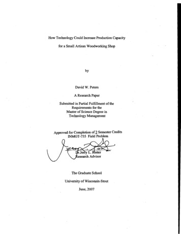
2011KiporPowerSystems,Inc.1.2 WIRING DIAGRAM IG1000 through 2010 Model Year3
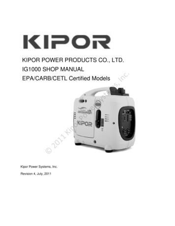
1120KiporPowerSysms,teInc.IG1000 2011 Forward4
1120KiporPowerSysms,teInc.IG2000P 2011 forward5
2. SERVICE INFORMATION2.1 The importance of proper servicingProper servicing is essential to the safety of the operator and the reliability of the generator. Any erroror oversight made by the technician while servicing can easily result in faulty operation and/or damage tothe equipment or injury to the operator.Improper servicing can cause an unsafe condition that can lead to serious injury or death.Follow the procedures and precautions in this shop manual carefully.c.Some of the most important precautions are stated below.ms,In2.2 Important safety precautionsSysteBe sure you have a clear understanding of all basic shop safety practices and that you are wearingappropriate clothing and safety equipment. When performing maintenance or repairs, be especiallycareful of the following:Read the instructions before you begin, and be sure you have the tools and skills required toperform the tasks safely. Be sure that the engine is off before you begin any maintenance or repairs. This will reduce thepossibility of several hazards:KiporPower 2011- Carbon monoxide poisoning from engine exhaust.- Burns from hot parts.- Injury from moving parts. Do not run the engine unless the instructions tell you to do so. Keep your handsand clothing away from rotating parts. To reduce the possibility of fire or explosion, exercise extreme caution whenworking around gasoline. Use only a nonflammable solvent, not gasoline, to cleanparts. Keep cigarettes, sparks and flames away from all fuel-related parts.6
2.3 Service rulesUse genuine KIPOR or KIPOR-recommended parts and lubricants or their equivalents. Parts thatdo not meet Kipor’s design specifications may damage the engine. Use the special tools designed for the product. Always install new gaskets, O-rings, etc. when reassembling components. Clean parts in cleaning solvent upon disassembly. Lubricate any sliding surfaces beforereassembly. After reassembly, check all parts for proper installation and operation. Many screws used in this machine are self-tapping. Be aware that cross-threading or overtightening these screws will strip the threads and ruin the hole. Use only metric tools when servicing this engine. Metric bolts, nuts and screws are notinterchangeable with non metric fasteners. The use of incorrect tools and fasteners will damagethe engine.Electrical precautionsSys2.4tems,Inc. Hold the connector body to disconnect the connector. Do not disconnect by pulling the wireharness. To disconnect the locking connector, be sure to unlock first, and then disconnect. Check the connector terminals for bend, excessive extrusion, missing terminals, or otherabnormalities before connecting the connector. To connect, insert the connector as far as it goes. If the connector is a locking type, be sure that itis locked securely. Check the connector cover for breakage and check whether the connector female terminal is notopened excessively. Then, connect the connector securely. Check the connector terminal for rust.Remove the rust using an emery paper or equivalent material before connecting the connector. Set the harness clips in the specified places of the frame securely, and secure the wireharnesses. Clamp the cables securely. Clamp the wire harnesses securely so that they do not interfere with the rotating parts, movingparts and hot parts. Route and connect the wire harnesses properly. Be sure that the harnesses are not slack,twisted or pulled overly taut. Route the wire harnesses properly so that they do not contact sharp edges and corners and theend of the bolts and screws on the body. 2011KiporPower 7
If a wire harness must contact the end of the bolts or screws or sharp edges and corners, protectthe contact part of the harness with a loom or by winding with electrical insulating tape. If the wireharness has a grommet, set the grommet securely. Take care not to pinch the wire harnesses during installation of a part. If a wire harness hasdamaged insulation, repair by winding with electrical insulating tape. When using an electrical tester like a volt/ohm meter or clamp on meter, read the manufacturer’soperating instructions carefully before operating the tester. Be sure that the tester battery is fullycharged and the meter is functioning properly2.5 Serial numberKiporPowerSystems,Inc.The generator serial number identifies your particular unit and is important when ordering parts andaccessories. It is also used by your dealer and distributor for warranty administration. 2011The generator serial number is stamped on the engine block to the right of the oil dipstick. It is also on alabel on both ends of the generator carton as well as the certificate of quality.8
2.6 Maintenance standardsMaximum speed without loadCylinderSleeve I.D.Skirt O.DPistonPin bore I.D.Piston pinO.DHeightRing side clearance1st ringerowRing side clearance2nd ringKiporPPiston ringRing end clearance2011WidthHeightRing side clearance Oil ringRing end clearanceWidthSmall end I.DConnectingrodBig end I.DCrankshaftValvesCrank pin O.D.ValveclearanceStem O.D.IntakeExhaustIntake9—1.712-1.714 in43.500-43.520 mm1.711-1.712 in43.460-43.480 mm0.3937-0.3940 in10.002-10.008 mm0.3934-0.3937 in9.994-10.000 mm0.030-0.031 in0.77-0.79 mm0.0008-0.0024 in0.02-0.06 mm0.0039-0.0098 in0.10-0.25 mm0.063-0.071 in1.60-1.80 mm0.038-0.039 in0.97-0.99 mm0.0008-0.0024 in0.02-0.06 mm0.0039-0.0098 in0.10-0.25 mm0.071-0.078 in1.80-2.00 mm0.053-0.058 in1.35-1.48 mm0.0008-0.0067 in0.02-0.17 mm0.0079-0.1180 in0.20-0.30 mm0.3942-0.3946 in2.00-2.40 mm0.3942-0.3946 in10.012-10.024 mm0.5911-0.5915 in15.015-15.025 mm0.5896-0.5899 in14.975-14.985 mm0.0031-0.0039 in0.08-0.10 mm0.0039-0.0059 in0.10-0.150.156-0.157 in1.716 in43.595 mm1.707 in43.350 mm0.3955 in10.050 mm0.3920 in9.950 mm0.028 in070 mm0.0059 in0.15 mm0.03140.80 mm0.055 in1.40 mm0.0354 in0.90 mm0.0059 in0.15 mm0.03140.80 mm0.063 in1.60 mm0.049 in1.25mm0.0090 in0.23 mm0.0354 in0.90 mm0.3965 in1.80 mm0.3965 in10.070 mm0.5937 in15.080 mm0.5866 in14.900 mm--------0.1535 inSysWidthHeight5500 100 rpmteRing end clearanceService limitc.EngineStandard(mm)InItemms,Part
ExhaustValve springGuide I.D.IN/EXFree lengthIN/EXCam wheelCam heightO.DCamshaftCamshaft bearing I.D.O.D.(Rocker arm shaft)InRocker armc.I.D(Rocker arm)teSysGapPrimary sideSecond sideResistanceerIgnition coilAir gapowPulse coil(Trigger)ms,I.D.(Rocker arm shaft bearing)Spark plug3.965—3.980 mm0.1557-0.1562 in3.955—3.970 mm0.1575-0.1579 in4.000—4.012 mm0.925 in23.5 mm1.101-1.103 in27.97-28.03 mm0.1963-0.1967 in4.988-4.996 mm0.1976-0.1988 in5.02-5.05 mm0.1575-0.1579 in4.000-4.012 mm0.1574-0.1579 in3.988-3.996 mm0.1574-0.1579 in4.000-4.012 mm0.024-0.028 in0.6—0.7 mm0.8—1.3 Ω15 —21 kΩ0.020-0.0295 in0.5-0.75 mm80 130ΩKiporPResistance3.900 mm0.1540 in3.900 mm0.2598 in4.060 mm0.866 in22 mm1.062 in26.97 mm0.1949 in4.950 mm0.20085.10 mm0.2598 in4.050 mm0.1590 in3.950 mm0.1594 in4.050 mm———————ItemTypeStandard (Ω)Ignition windingOuter chargingwindingSub windingMain .25-0.352.0-3.011Part 20ResistanceResistance2.7 Torque valuesItemSpecificationConnection rod boltSpark plugFlywheel nutM5X0.8X25M10X1.0X13M10X1.25M5 Bolt, nutStandard torqueTightening torqueN·m8-1011-1348-524.4-6.06-8Ft lb.5.9-7.4M6 Blot, nut5.9-7.4Note: Use standard torque values for fasteners that are not listed in this table.108-10
3. TroubleshootingThis troubleshooting section contains troubleshooting trees organized by common groups of symptoms.Some testing information is contained in these sections. The following chapters of this manual focus onindividual components and sub assemblies which will give you the assembly and reassemblyprocedures along with detailed specifications and testing procedures.3.1 General symptoms and possible causesFuel switch cloggedCleanCarburetor faultyReadjust and cleanIgnition coil faultyInspect and replaceSpark plug faultyInspect and replaceTrigger faulty or trigger clearanceInspect and replaceSpark plug cap loosesFix it securelyLow oil alarm faultyInspect and replaceThrottle control motor (steppingSet in fully close or half close positionAdjust and/or disassemble and cleanInspect and replacemotor) faultyInverter unit faultyInspect and replaceValve clearance misadjustedReadjust 2011high or too lowKiporPstabilize, tooCarburetor faultyInspect and replaceerThrottle opening faultInspect and replaceowIgnition winding faultydoes notInfaultyIgnitor faultyEngine speedc.Cleanms,hard startingFuel tank tube cloggedtenot start orCleanSysEngine doesFuel filter clogged11
3.2 Hard startingNo fuelCheck the fuel level in the tank.Add fuel and restart the engine.Sufficient fuelLoosen the drain screw andcheck whether fuel reached thefloat chamber and the oil level.AbnormalCheck the fuel lines for blockage.NormalDryRemove the spark plug andcheck for wet or fouled electrode.Check for blockage in the carburetorintake port and nozzle.Clean the electrode and restart,Ensure the choke is not closed. Ifflooding is severe, check thecarburetor float No spark orInstall the spark plug and ground weak sparkthe electrode. Check the spark.ms,Inc.WetNormalerowKiporPInstall a compression gauge inthe spark plug hole and check thecylinder compression by pullingthe recoil starter rope severaltimesLow cylindercompression1. Check the valve clearance2. Check for carbon deposits in thecombustion chamber.3. Check for worn guides and seals.4. Check for worn piston, piston ringor cylinder.2011Normalcompression Install the spark plug securely.Restart the engine according tothe starting procedure. Cylinder compression check1. Remove the spark plug cap and spark plug.2. Install a compression gauge in the spark plug hole. Pull the recoil starter rope several times with forceand measure the cylinder compression.Cylinder compression80 psi/0.55Mpa12
C. Ignition system Fill in oil to the required level.UR5.c. Use spark plugIn Spark plug inspectionms,1. Disassemble spark plugte2. Install spark plug onto spark plug cap.Sys3. Set the oil switch to the “ON” position. Ground the negative (—) electrode (i.e. threaded part) of thespark plug against the shroud and pull the recoil starter rope to check the spark plug. Normally youKiporPowershould see the spark jump the electrode gap when the plug is firing. Don’t pull the recoil starter while touching the high tension wire with wet hands. High voltagegenerates, which is very dangerous.20fuel completely.11 Fire may be caused if fuel spilled around the spark plug, so make sure that you test after draining off Fuel inside cylinder will be burnt if the spark plug is near the hole, so please turn off the engine first.Pull the recoil starter several times to release the unborn gas in the cylinder.13
3.2 Hard Starting ContinuedMeasure the spark plug gap andperform the spark plug test. Gap:024-028 in (0.6—0.7mm)No sparkPerform the spark test again using a Good sparknew spark plugReplace the spark plugNo sparkRemove the control panel. Perform Good sparkspark test with a new ignition module.c.Replace the ignition moduleCheck the resistance of motorignition windingReplace the low oil alarmowerGood sparkKiporPNo sparkReplace the engine switchSysNo sparkDisconnect the low oil alarm andperform spark testms,Good sparkteCheck the engine switchInNo sparkAbnormalReplace the motor stator11NormalAbnormal 20Check the triggerNormalCheck the ignition coil resistanceand high pressure cable, highpressure insulation cap.Replace the trigger or readjusttrigger clearanceAbnormalReplace the ignition coilNormalInspection or replace wire harness.14
3.3 Engine oil level is low, but engine does not stop. (Defective oil switch)Drain out oil completely, disconnect alarm No continuityconnection wire, and check the continuityReplace the oil level alarmbetween alarm outlet terminal and ground.ContinuityReset the alarm connection wire, disconnect No continuityRepair or replace the wireignition module and check the continuityharnessesbetween the plug orange wire and ground.ContinuityIgnition module fault: replace module.Check whether there is enough fuel in thefuel tank.SysKiporPNo blockedCheck the fuel supply line for blockageAdd fuel and restart the engineBlockedClear the fuel switch and fuelfilterBlockedClear or replace the fuel supplylineowCheck the fuel switch and fuel filter forblockageerSufficient fuelNo fuelms,Sufficient oilFill in oil and restart the engineteOil alarmCheck the oil level and oil alarmInc.3.4 Engine stops running (Throttle is at the correct position)No blockedBlockedClean or replace carburetor2011Check the carburetor nozzles for blockage Not blockedCheck seal between inlet gasket andcarburetor heat insulation blockAbnormalNormalMeasure the cylinder compressionAbnormalNormalCheck the trigger clearanceAbnormalNormalPerform the throttle control system test15Tightengasket.nutsand/orreplace1. Check the valve clearance2. Check the carbon deposit incombustion chamber3. Check the piston, piston ringand cylinder for damageReadjust the trigger clearance
3.5 Engine speed can’t increase or unstable (choke is at the correct position)BlockedCheck the air filter element for blockageClear the air filter elementNo blockedAbnormalCheck the valve clearanceReadjust the valve clearanceNormalRemove the spark plug and check theelectrode clearance for carbon depositAbnormalClear electrode, adjust clearanceor replace the spark plugNormalCheck e and clearc.No blockageNormalKiporPPerform the throttle control system testIn1. Check the valve clearance2. Check for carbon depositsin combustion chamber3. Check the piston, piston ringand cylinder for damageowerNormalAbnormalSysMeasure the cylinder compressionScrew the nut, and replace thepapery gasket or heat insulationblockms,AbnormalteCheck sealing of inlet line papery gasket andcarburetor heat insulation block3.6 Engine speed too high or too lowAbnormal11Check the AC outputPerform the generatortroubleshooting following thesection onf “No or low AC output” 20NormalCheck the throttle control motorAbnormalNormalReplace the inverter unit16Replace the throttle control motor
3.7 Smart system doesn’t work with zero load or engine speed doesn’t increase with Smartsystem on and load connected.AbnormalCheck the AC outputPerform the generatortroubleshooting following thesection on “No AC or low voltage”NormalAbnormalCheck the throttle control motorReplace the throttle control motorNormalAbnormalReplace the smart Throttle switchc.Check the Smart Throttle switchAbnormalRepair or replace the wire harnessms,Check Smart switch connection wireInNormalSysteNormal3.8 No or low AC outputOFFONKiporPIs the overload indicator light ON?owerReplace the inverter unitAbnormalPerform the throttle control systemtest 2011Is the engine speed normal?Smart switchON: 4200 100rpmOFF:5500 100rpmDisconnect the load, and restart theengineNormalStop the engine and check the ACreceptacleAbnormalReplace the AC receptacleNormalDisconnect the main winding and subwinding (CG) 6p connector on inverterunit. Start the generator and measurethe voltage between pins 1&4, 2&4, 1&2.Each reading should be at least 290volts.AbnormalNormalReplace the inverter unit171. Check and repair stator wiringharness or replace stator2. Check rotor magnetism. Ifdecreasing, replace the rotor
3.9 No DC outputCheck the engine speedNormalAbnormalPerform the throttle control systemtroubleshootingAbnormalCheck the DC receptacleReplace the DC receptacleNormalNormalNormalReplace the rectifierCheck and repair the wiringharness or replace thestatorSyser 2011KiporPThe rotor loses excitation,replace the rotorAbnormalowMeasure the resistancebetween the two blue wireson the rectifier.Resistance: 0.16-0.20Ωc.AbnormalInCheck the rectifierReplace the fusems,NormalAbnormalteCheck the 5 amp fuse18
4. Maintenance4.1 Maintenance scheduleRegular service periodItem perform at every indicatedmonth or operating hour interval,Each useFirstEvery 3Every 6Everymonth ormonths ormonths oryear or20 Hrs.50Hrs.100 Hrs.300 Hrs.whichever comes firstCheckEngine Oil ReplaceCheckAir filter Clean *Clean-Adjust Spark catcherClean-Adjust Valve clearanceCheck-AdjustFuel tank and filterCleanFuel lineCheck ** **ms,Inc.Spark plugEvery 2 year (Replace if necessary)teNote:er** Service by KIPOR authorized service center.Sys* Service more frequently when operating in dusty areas.ow4.2 Engine oilKiporP Checking for the oil levelStop the engine and check the oil level, be sure to put the engine on a flat and level surface whenchecking.1. Loosen the maintenance cover screw and remove the cover. 20112. Remove the oil filler cap and check the oil level.19
c.In Replace the engine oilte1. Remove the oil dipstick and oil drain bolt, drain out dirty oil.ms,3. If the oil level is low, add to the edge of the oil filler port.Sys2. Reinstall the oil drain bolt tightly.er3. Fill with fresh oil of the proper viscosity (see operator’s manual).ow4. Check the oil level.5. Tighten the oil dipstick.KiporP Drain the used oil while the engine is warm. Warm oil drains quickly and completely. Avoid burns fromhot oil.4.3 Checking the low oil alarm111. Disconnect oil alarm connector when the engine is still running, connect the two plugs, be sure that oil 20alarm lights and engine stops.20
Systems,Inc.2. Stop engine, disconnect oil alarm connector, check the connector conduction, no conduct is normal.er3. Drain out the oil inside engine and check the conduction, conduct is normal.ow4.4 Air cleanerInspection/Cleaning:KiporP1) Loosen the cover screw and remove the maintenance cover.2) Disengage the locking tab by pushing it, and remove the air cleaner cover.3) Remove the element from the air cleaner case.4) Clean the element in warm soapy water, rinse and allow to dry thoroughly and allow to dry.115) Dip the element in clean engine oil and squeeze out all the excess oil.206) Install the air cleaner element in the air cleaner case. Clean the air cleaner rubber and the air cleaner case if necessary. Be sure that the air cleaner coverseals are set securely.7) Install the air cleaner cover. Be sure that the air cleaner cover seals are set securely.8 Install the maintenance cover securely.21
c.Inms,teCautionSys A dirty air cleaner willrestrict
Use genuine KIPOR or KIPOR-recommended parts and l ubricants or their equivalents. Parts that do not meet Kipor’s design specifications may damage the engine. Use the special tools designed for the product. Always install new gaskets, O-rings, etc. when reassembling compon