Transcription
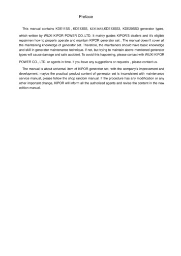
PrefaceThis manual contains KDE11SS,KDE13SS, KDE16SS,KDE13SS3, KDE20SS3 generator types,which written by WUXI KIPOR POWER CO.,LTD. It mainly guides KIPOR’S dealers and it’s eligiblerepairmen how to properly operate and maintain KIPOR generator set . The manual doesn’t cover allthe maintaining knowledge of generator set. Therefore, the maintainers should have basic knowledgeand skill in generator maintenance technique. If not, but trying to maintain above-mentioned generatortypes will cause damage and safe accident. To avoid this happening, please contact with WUXI KIPORPOWER CO., LTD. or agents in time. If you have any suggestions or requests,please contact us.The manual is about universal item of KIPOR generator set, with the company’s improvement anddevelopment, maybe the practical product content of generator set is inconsistent with maintenanceservice manual, please follow the shop random manual. If the procedure has any modification or anyother important change, KIPOR will inform all the authorized agents and revise the content in the newedition manual.
Content1. Safety1.1 Attentions1.2 Install, move and transport genset1.3 Fire prevention and explosion prevention1.4 Protection1.5 Chemical1.6 Electric equipmentWarning labels and position1.8 Rescue the injured hurt by electricityLifting, installation and deposit2.1 Lifting2.2 Installation2.3 Deposit3. Technical parameters3.1 Main technical parameters of generator set3.2 Maintenance parameters of generator set3.3 Maintenance parameters of generator set3.4 Electrical systematic elementary diagram3.5 Fastening torque values4. General explanation4.1 Shape and structure of generator set4.2 Electric cabinet4.3 Diesel engine4.4 AC brushless four poles synchronous generator4.5 Genset fuel supply system4.6 Genset structure air dust cooled system and water cooled system5. Handling instruction of electric control parts5.1 Operation panel5.2 Operation of digital display controller function5.3 ATS connects with generator set5.4 Connection of load6. Daily inspection and regular inspection6.1 Regular inspection procedure7. Operation indication7.1 Fuel lubrication water cooled7.2 Battery cell operation7.3 Preparation before operation7.4 Used method8. Maintenance and repair of electrical system8.1 Starting electrical motor8.2 Charging generator8.3 Generator
9. Maintenance and repair of engine9.1 Installation drawing and some parts names9.2 Engine disassembly and assembly9.3 Engine check and maintenance10. Failure and resolution10.1 Doesn’t generate power or generate power abnormally10.2 Digital panel electrical system10.3 Warning system failure10.4 Starting failure10.5 Engine rotation speed unsteady10.6 Exhaust color anomaly10.7 Engine under-power10.8 Fluctuation of service10.9 Engine overheat10.10 Hard shutdown10.11 Abnormal sound while engine operating
1.Safety1.1 AttentionsThank you for purchasing KIPOR generator set.Please carefully read and thoroughly understand this introduction and precautions and attentionsmarked on the machine prior to operation, check and maintenance. Then official operation is allowed.Please carefully read the following safety indications for avoiding unexpected accidents and damages.This manual identifies conditions of risks and damages if operation is incorrect with following.The sign shows that if not obey the indication will lead to serious injury anddeath accident.DangerIndicates the potential risk should be noted, if not obey the indication will lead toserious injury and death accident.WarningThe sign shows that if not obey the indication might lead to mild injury anddamage.Attended To get the best efficiency and ensure the longest life of generator set, must do preventativemaintenance in accordance with this manual. If generator set operates in bad status condition, it willshorter duration of some parts. Be sure all the servicemen have professionary training. However, it is impossible for our company to expect all risks concerning conditions ofoperation, check and maintenance. Therefore warnings contained in the introduction and identified onthe machine are exclusive and complete. User shall take own responsibility for safety if user doesoperation, check and maintenance not mentioned herein.1.2 Install, move and transport gensetFor safety, please observe following matters needing attention.
Warning According to correlative standard, norm and other requests containing earth connection andcreepage fault to connect wire. Do not lift the machine at non-designated positions because of insufficient lifting strength.Otherwise falling machine leads to mechanical damage or human injury. Upon lifting the machine, please use the designated metal hook in the center of engine cover. Do not stand under lifted machine. Do not lift the machine when engine runs or don’t run engine when lift the machine. Incorrect overlapping-storage may cause falling and overturn of machine and mechanicaldamage. Place the machine on the flat and solid ground. Keep machines level. Ensure that ground canbear overlapping weight.Max two layers of overlapping storage are allowed. Check if machine bolts are loose or missing. Separate machines with wooden lumps. Keep all wooden lumps bearing same weight. Do not run overlapped machines. Otherwise it may cause overturn and falling.1.3 Fire prevention and explosion prevention
DanThe fuel and exhaust-smoke of the generator are easily ignited andexplosive. Carefully deal with these matters and nip them in the bud. The BCand ABC fire extinguishers in the machinery room should be in good condition.Users must know how to use the fire extinguishers.gerEnsure the ventilation is enough in the machinery room.Ensure the machinery room, floor and generator surface are clean, if the fuel, battery solution orrefrigerating fluid leak out, please clear them up immediately.Don’t put inflammables near by generator set.Put the oily rag into the metal container with cover.Smoking, sparking or other open flame action near by the battery and fuel are not allowed.Because the volatile gas from fuel and the hydrogen from battery charging will cause explosion by openflame.Cut off the power supply of battery charger before connecting or shut-off battery.The conducting objects like metal tool should be away from exposed live part(like outputelectrode), prevent the arc-spark and fuel or gas explosion caused by arc-spark.Don’t fill fuel when the generator set is working.Don’t start the generator in the condition of the fuel leaked.Start the generator repeatedly, check valve and heat machine stops will cause excess unburnedgas in the exhaust system. Please be very careful by now, there is potential explosion danger. Youshould start generator set after exhausting gas.1.4 ProtectionThe safety cover is installed on the rotating place of the generator set, becareful all the risks of moving parts to people when the generator set starts.DangerWhen the safety cover is took apart, don’t start the generator set. When the generator set isrunning, don’t reach under or nearby the safety cover to maintain.When maintaining, the worker should wear work clothes, gloves and hat.Palm, arm, long hair, loose-fitting clothes and jewelry should keep away from the moving orrotating parts of generator set.Don’t touch high temperature parts before generator cooling.1.5 ChemicalThe fuel, oil and battery solution belong to product of chemical industry, ifimproperly used or managed them, it is harm to human body.
WarningDon’t swallow or let skin touch harmful chemicals like fuel, oil, battery solution. If swallowing themby careless, you should see a doctor in time, if the skin touches them, you should wash your eyes withsoap and clean water.Don’t wear clothes stained by fuel, lubricant and battery solution.When dealing with battery, please wear acid-proof apron, face shield or eye protector, once thebody is stained by acid liquor, wash it immediately with abundant water. If the acid liquor splashes intoeyes, please wash your eyes with clean water or 10% dilute boric acid solution, and see a doctor intime.1.6 Electric equipmentCorrect installation, operation and maintenance can make sure the electricequipment work efficiently and safely. If not, the injury even death is very likelyto occur.DangerGenerator set must be connected load by qualified or experienced electrician, connected loadmust conform to relevant electrical rules, standards and norms.Ensure the earth specification of generator set conforms to local safety rules and standards ofelectric.Don’t stand in the water or humid ground to connect or dismantle load.When the generator set generates electricity, human body or metallic object without insulationprotection doesn’t touch with live parts of generator set or power supply wire.After connecting or disassembling load, please reset distribution cabinet cover immediately. Don’tstart generator set at open distribution cabinet cover.The load or electric system supplied power by this generator set must consist with electricalcharacter of this generator set. And the power should be in the range of capacity of this generator set.When maintaining the generator set, make sure you remember to cut off all the external power.Keep all the electric equipments dry and clean. Please replace wire and insulator immediately ifthey are any cracking, laceration or wearing. Keep wire and connection pole clean and closeconnected.Ensure all the electric parts and power connection of generator set have proper protection.Only BC or ABC grade fire extinguisher can be used for electric equipment fire fighting.When connecting into battery, keep positive pole and negative pole upright, otherwise it maycause serious damage to electric equipment.1.7 Warning labels and position1.7.1 Lable position
4375621101112891. Attention 2. Pay attention to exhaust 3. Pay attention to scalding 4. Pay attention to hightemperature 5. Lifting position6. Prevent flame and fire 7. Forbid lifting the machine 8. Payattention to handling of storage battery 9. Avoid being involved in the running machine 10. Low oilpressure warning 11. Pay attention to electric shock 12. Attended operations1.7.2 Warning label1. Pay attention toCheck the engine while it is inthe cooling state. Check theengine after it stopped. Becare not to be scalded bymuffler and exhaust pipe.4. Pay attentiontemperaturetohigh2. Pay attention to exhaust3. Pay attention to scaldingDangerThe exhaust is harmful to thehealth. Do not run the unit indoors or in poor ventilatedarea.Don’t touch the water tank,while it’s too hot to preventfrom the scalding.5. Hooking position6. No Smoking
Don’t open the water tankwhile high temperature.You may be scalded due tothe hot water.Hooking position7. Hooking is forbidden.8. Pay attention to not move batteryHooking is forbidden.Don’t move the battery when thegenerator is running.10. Low oil warningDon’t run engine without checking oil level in case of autostop or lighting of oil pressure alert lamp. Check engine oilbefore each start. Be sure to use SEA 10W30 grade CC.Smoking or spark isforbidden near to the fillingport. Otherwise the fire willbe happened.Be sure to refuel the unitafter the engine is stopped.9. Avoid being involved inthe running machineDon’t put the hand orfingers into the machinewhile running. Otherwiseinjury may be happened.11. Pay attention toelectric shock
12: Attended operations Please read the user manual carefully and operate the unit safelyPlease read the user manual carefully before operation.If the user manual and safety label are broken, please order from Kipor. There is possibility of electric shook and fire. Don’t connect the unit to the utility lines or homewirings. Refuel the unit after the engine stopped to prevent the fire. There is danger of electric shock and injury. Before starting, please firstly confirm that thebreaker is on the position of OFF. Don’t move the unit while running to prevent from the injury. Please operate by professional man with rich technology. safety information:There is high-voltage part, rotation part and high-temperature part. Do run the engine afterclosing the lid. Check and service the unit after the engine is completely stopped.1.8 Rescue the casualties shocked by electricityIf electric shock occurs, cut off switch, shut down generator set emergently. If the power supply can notbe cut off, please separate the casualties shocked by electricity from the conductive matters as quicklyas you can. Avoid to directly touch with the conductive matters and the casualties shocked by electricity,please remove the casualties shocked by electricity with dry batten or dry clothings or other insulatingmaterialIf the injured was in a coma, give rescue breathing immediately according to the needs. Otherwise, theinjured will die. When the heart has stopped, do cardiac massage.2. Lifting and transportation, installation and storage
2.1 Lifting and transportation2.1.1 Lifting Lift generator with the lifting hook on the top of cover. Do not stand under thelifted generator. If the generator falls down, it may cause hurt.Warning If lifting the generator with transportation hook or other parts, there is the risk of mechanical damageor falling-down. Do not lift or move the running generator. Some irrevocable errors like fan damage may occur. Don’t run the lifted machine.2.1.2 Transportation If shipping with the truck, please fix the generator on the loading table in the truck for safetyconcern. Bind the generator with ropes at left and right hands indicated on below drawings after loading.
2.2 InstallationPlease work the machine in the well-ventilated place. Badventilation causes breath of waste gas thus to death.Danger Do not work the generator in the building or place with cover, bad ventilation or static exhaust. Do not work the generator in the place with bad ventilation such as inside stockroom, tunnel, cabin orenclosure channel. If it is necessary to run the machine on mentioned conditions, necessarily extend exhaust pipe outsideof room and provide proper ventilation device to ensure sufficient ventilation. Prevent exhaust vent direct to passerby or other's family.2.2.1 Pay attention to vibrationRunning machine produces vibration as inside engine is working.Please observe the following requirements upon installation.1)Place the generator on the solid ground and keep it level.Abnormal vibration may occur if generator runs on the uneven ground.2) If there is uptown around, residents may complain about noise. Therefore please install the generatorafter solid foundation is completely finished. Consult local sales department of KAMA for detailedinformation concerning vibration specification and foundation project.2.2.2 Pay attention to noiseThere is great noise if operator opens the side door as inside engine is working.In addition, there is still certain noise even if side door is close.1)Close the side door after machine is installed.2)If there is uptown around, residents may complain about noise. Therefore please take additionalmeasures against noise. Consult local sales department for detailed information concerning noisespecification.
2.2.3 Pay attention to installationThis generator is portable and used as main or auxiliary power supply for outside work. Installation shallconsider below requirements.1)Please install the machine on the flat and solid ground. Make sure bottom of the generator contactsground evenly. Error may occur due to generator vibration.2)If it is necessary to run the machine on the inclined ground, make sure the side with radiator upwardand inclination angle within 10 . Engine may face over-heat due to bad working of water temperatureswitch, air into cooling water pipe and etc.3)Keep machine at least 200-300mm away from walls upon installation. Keep air vent of radiator andsuction inlet and exhaust vent of engine upward. Prevent them from any jam. Otherwise temperaturerise or reduction of cooling airflow may cause over-heat of engine or reduction of rotation. In addition,temperature of exhaust or increase of load also may lead to shorter duration.4)Run the machine in the place free of moisture, dust and rubbish and with fresh air.Electricity leakage causes electric shock. If air vent of radiator is jammed, over-heat of engine mayoccur.5)Place the generator near to working equipments like motor, lamps and etc.Long line reduces efficiency because of large resistance and electricity loss. And electricity fee turnsmore.6)When the generator loads down, please pay special attention to impact load and release loadsgradually and evenly.
2.3 StoragePlease store generators as following if two-layers storage is required. Check if generator hood is damaged or screw is loose or released. Check if the ground is flat and solid and can bear static weight of overlapped generators. Place the wooden lumps between generators. Prevent generators in the upper layer from inclination. Prevent generators in the upper layer heavier than those in the lower layer. Do not run the generator at the status of storage.2.3.1 Long-term storagePlease implement following maintenance for the generator idle for long-term. Drain off cooling water in cold season or at the status of long-term storage.(Mentioned action is no need if anti-freezing liquid is used.)1)Take off upper hood and open radiator cover.2)Take off drainage plug of cooling water in the frame of generator to drain inside water.3)Loosen the drainage plug at the side of cylinder and drain out the water.4)Close radiator cover, hood and drainage plug after drainage finishes.It is necessary to drain off cooling water. Otherwise rest cooling water in theengine may freeze and expand thus to damage the machineAttention
Please clean mud, dust and oil remained on the machine surface. Must finish periodic check prior to maintenance. In order to prevent dew concentration in the fuel tank. Drain off fuel or fill fuel completely. Disconnect cable of storage battery with (-) pole. Apply lubricant to operating devices and relevant connections. Please cover the plastic hood and similar parts in order to prevent water or dust into control box,radiator and muffle of exhaust pipe. Store the machine in the place without moisture or dust and with good ventilation. Please charge the storage battery once per month to resolve intrinsic shelf depreciation duringmachine storage. Please do no-load running for short time and at low speed if machine is idle for long term and prior toload running.3.Technical parameters3.1Main technical parameters of generator set3.1.1Overall SS3Overall length1570mmWidth780mmHeight1050mm
3.1.2Main technical parameters(single-phase generator set)ModelRated 1113Rated voltageV115/230120/240115/230120/240Rated 00Rated output capacityMax. outputGeneratorKDE11SSRated rotation speedCircuit modeSingle-phase and three circuitsPower factor1.0Insulation gradeFSteady-state voltagedeviation (%) 2.5Frequency step down (%) 0.5Air circuit breaker(selectedvalue)40A50A50APole number50A4Brushless self-excitation and constant voltageExcitation mode(with AVR)Panel typeDigital ReceptacleTwo single phase receptaclesConnection poleWithDC12V outputWithoutFuel tank capacityLContinuous running timehOverall dimension: LXWXHmmNet weightKg675685Kg750760Working assorting weightNoise level (7m)Structure typedB(A)65171517151570 780 10550HZ:51 60HZ:53Ultra silent
3.1.3 Main technical parameters of three-phase generator setGeneratorModelKDE13SS3KDE15SS3Rated frequencyHz50605060Rated output capacityKVA10.613.112.515Max. outputKVA11.614.51416.5Rated voltageV230/400240/416230/400240/416Rated currentA15.318.21820.8Rated rotation speedrpm1500180015001800Circuit modeThree phase, four lines, Y connectionFactor power0.80.8(lag)Insulation gradeFSteady-state voltagedeviation (%) 2.5Frequency step down (%) 0.5Air circuitbreaker(selected value)16A20A20APole number25A4Brushless self-excitation and constant voltageExcitation mode(with AVR)Panel typeDigital ReceptacleTwo single phase receptaclesConnection poleWithDC12V outputWithoutFuel tank capacityL65Continuous running timehOverall dimension:LXWXHmmNet weightKg675685Working assorting weightKg750760171517151570 780 1050
Noise level (7m)dB(A)Structure type50HZ:51 60HZ:53Ultra silentUltra silent3.2 Maintenance parameter of engine3.2.1 Specifications and characteristicsModelKD388KD388ZThree-cylinder, vertical,water cooled, four stroke,direct injection,superchargingThree-cylinder, vertical,Water cooled,four stroke, direct injectionTypeBore x StrokemmDisplacement88 90L1.642Compression ratio18.2Firing order1-3-2(from flywheel terminal)Rated power/Rated rotation speedkW/r/minMax. torque (N·m)Lubricate /1800116/1800Pressure splashed mixing typeStarting typeElectric starterRotation direction of output end (faceto flywheel)AnticlockwiseFuel brandFuel consumption0#(summer), -10# or -20#(winter), -35#(chillness)(Rated rotationspeed g/(kW·h)/r/min230/1500
Lubeoil brandSAE 10W-30、20W-40 or L-ECD gradeLube capacity L6.9Fuel consumption g/(kW·h)2.72Starting motorV,kW12V 1.4kWCharging generator capacity V,A12V 15ABattery capacity V,AH12V 80AHOverall dimension: LXWXH mmNet weight610 480 642kg1701753.2.2 Fit clearance and magnitude of interferenceNO.NameStandard dimensionFitdimension1Cylinder diameter / Piston headΦ88 0.0250/Φ88-0.49-0.51land diameter2Cylinder diameter / Piston skirtΦ88 0.025/Φ88-0.140-0.16upper diameter3Cylinder diameter / Piston skirtΦ88 0.025/Φ88-0.050-0.07diameter4Piston pin pore diameter / Piston0Φ26 0.008 0.002 /Φ26-0.006pin diameter5Height of ring groove / Height of-0.012 0.06 0.04 /2-0.02the 1st ring6Height of ring groove / Height of-0.012 0.04 0.02 /2-0.02the 2nd ring7Height of ring groove / Height of-0.0104 0.04 0.02 /4-0.025the 3rd ring0.49 0.5350.14 0.1850.05 0.0750.002 0.0140.05 0.080.03 0.060.03 0.0658Piston ring gap clearance Ⅰ0.25 0.409Piston ring gap clearance Ⅱ0.25 0.3510Piston ring gap clearance Ⅲ0.15 0.3011Aperture diameter of connecting0Φ26 0.025 0.015 /Φ26-0.006rod bushing / Piston pin diameter12Aperture diameter of connectingΦ48 0.039/Φ48f5(-0.0250-0.036 )0.015 0.0210.025 0.075Remark
rod bearing / Connecting rodjournal13Aperture diameter of main bushΦ54 0.043/Φ50f5(-0.0250-0.036 )/Main journal14Crankshaft axial clearance028 0.15 0.10 /28-0.03815Side clearance between journal028 0.20 0.10 /27.7-0.030.025 0.0790.10 0.188and connecting rod bid end0.40 0.53/Journal gap clearance16Connecting bolt hole/0Φ9.5 0.015/Φ9.5-0.0090Bolt locating journal17Camshaft bore / CamshaftΦ45H7( 0.025)/Φ45e7(-0.0500-0.075 )journal1819Camshaft axial clearanceAperture of machine stem/4.5 0.15 0.10 /4.5 0.05Φ12H7( 0.0180)/Φ12-0.016-0.027Outside diameter of valve stem20Idle gear seat hole / Idle gearΦ20H7( 0.021)/Φ20g6(-0.0070-0.020 )seat21Aperture of idle gear bushing /Φ46H7( 0.025)/Φ46f6(-0.0250-0.041 )Idle gear seat22Gear box oil pump / Diameter ofΦ90H9( 0.035)/Φ90(-0.080-0.12 )outside rotor232425Axial clearance of inside /Outside rotor of oil pump(Center of crankshaft to the top ofcylinder cylinder gasket) /Piston connecting rod crankshaft radiusAperture of valve guide / Inlet011 0.08 0.05 /11-0.02230 0.03 0.747.6 0.05 137 0.03 45 0.03Φ8H7( 0.015)/Φ8-0.0350-0.050valve rod diameter26Aperture of valve guide / ExhaustΦ8H7( 0.015)/Φ8-0.0400-0.055valve rod diameter27Aperture of valve rocker arm /Φ16H7( 0.018)/Φ16f6(-0.0160-0.027 )Axial diameter of rocker arm28Flywheel location aperture / Axial0 0.0240.05 0.100.05 0.200.016 0.0450.007 0.0410.025 0.0660.08 0.1550.05 0.10标准值1.10.96 1.240.035 0.0650.04 0.070.016 0.0450Φ85H8( 0.054)/Φ85h8(-0.054)0diameter of crankshaft flywheel0 0.108terminal29Aperture of cylinder cover guide /Φ13H7( 0.018)/Φ13 0.0650 0.050Outside diameter of valve guide30Hole of cylinder cover inlet valveseat / Outside diameter of inletvalve seat-0.032 -0.06Interference5Φ38H7( 0.025)/Φ38 0.120 0.10Interference-0.075 -0.12
31Hole of cylinder cover exhaustΦ31.5H7( 0.025)/Φ31.5 0.120 0.09valve seat / Outside diameter ofInterference-0.065 -0.12exhaust valve seat32Camshaft hole of cylinder block /Φ48H7( 0.025)/Φ48 0.100 0.08InterferenceOutside diameter of camshaft-0.055 -0.10bushing33Outside diameter of idle gear /Φ50H7( 0.025)/Φ50v7( 0.1060 0.081 )Outside diameter of idle gear-0.056 -0.106bushing34Aperture of connecting rod smallΦ29H6( 0.013)/Φ29 0.0420 0.026-0.013 -0.04end / Outside diameter ofApertureofcrankshaftgearΦ38H7( 0.021)/Φ38r6( 0.0500 0.034 )-0.013 -0.05/Journal of crankshaft gear36 Aperture of timing gear / CamshaftFlywheel ring gear / FlywheelInterference0Φ30H7( 0.0210)/Φ30r6( 0.041 0.028)-0.007 -0.04gear journal37Interference2connecting rod bushing35InterferenceInterference1Φ296H7( 0.052)/Φ296u7( 0.4020 0.350 )-0.298 -0.40rabbet circleInterference23.2.3 Main Adjusting Data TableItemNormal valueNon-compressionspaceheight inside the cylinder mm0.8 1.0Advance angle of fuel supply16 1 B.T.D.CInjection pressureValve closeand openphaseMpaInlet valveOpen at B.T.D.C 10 , close at A.B.D.C45 Exhaust valveMax.risedistanceinlet/exhaust valve mm20 0.5,Supercharge 22 0.5ofValve clearance mm ( coldOpen at B.B.D.C 56 , close at A.T.D.C12 8.90.10 0.15state)Air valve sub-quality productmmLube pressureMpa0.5 0.10.25 0.53.3 Maintenance parameter of generator3.3.1 Main parts maintenance detecting parameter of single-phase generator and generator set
Generator set modelKDE11SSKDE13SSGenerator 30.254When main winding is23V:L1L2 R1R2Eachwindingresistance measuringcondition of generator:Theambienttemperatureofis20 2 The measured valuedeviation on the rightform isΩ 10%Themeasuringconditions of resistancevoltage and current:Rated output voltage is230V, frequency is50Hz,ratedpower,ambienttemperature20 2%, the deviationis V 0.1%Main winding of rotor5.556.011.541.5419.519.5Sampling voltage V115115Exciter full field voltage V32.130.1Exciter full field current A1.311.01Rotorwinding ofexciterStatorwinding ofexciterU-VV-WW-UThreegroups aresameF( )F(-)3.3. Main parts maintenance detecting parameter of three-phase generator and generator setGenerator set modelKDE13SS3KDE15SS3Generator modelKF13-4PKF15-4PFrequencyEachwindingresistance measuringcondition of generator:Theambienttemperatureofis20 2 The measured valuedeviation on the rightform isΩ 740.6850.537Main winding of rotorRotorwinding ofexciterU-VV-WW-UThreegroups arethe same5.556.011.541.54
Statorwinding ofexciterThemeasuringconditions of resistancevoltage and current:Rated output voltage is230V, frequency is50Hz, rated power,ambienttemperature20 2%, the deviationis V 0.1%F( )19.519.5Sampling voltage V200200Exciter full field voltageV41.138.8Exciter full field current A1.691.32F(-)3.4 Principle diagram of electrical system3.4.1 Single-phase univoltage output
3.4.2 Single-phase dual voltage simultaneous output
3.4.3 Three-phase voltage output
3.5 Tightening torque valuesvalueItemTightening torqueThread specification(N·m )Cylinder cover boltM10 1.25 9880 5Main bearing boltM12 1.5 73120 5Connecting rod boltM9 4360 5Flywheel boltM10 1.25 3270 5Crankshaft pulley boltM14 1.5 30180 10M68 12M818 26M1045 60M1280 100M14130 150M16180 210M18240 270M20350 400M813 16M1020 28M1225 32M1438 45M1648 55Other bolts: mechanical propertyis 8.8 gradeJoint boltRemarkJJ typebolt 7T
4. General explanation4.1 Outlook and structure of generator set1. Fuel inlet10. Transportation hook2. Fuel meter11. Air vent3. Check side door(one side of generator)12. Exhaust vent4. Check side door(one side of machine)13. Cover of water tank5. Drain cock of cooling water14. Output panel6. Drain cock of lubricant15. Door of operation panel7. Drain cock of fuel16. Operation panel8. Cover of fuel tank17. Single-phase socket9. Lifting hook
1. Controller13. Lubricant filter2. Fuel tank14. Drain cock of lubricant3. Fuel feed pump(only for fuel tank with machine)15. Drain cock of fuel4. Fuel filter16. Engine5. Air filter17. Filter(Fuel/water separator)6. Exhaust vent18. Fuel feed pump(only for outside fuel tank)7. Cover of water tank19. Storage battery8. Water tank20. Operation panel(Instrument panel)9. Fan belt21. Single-phase socket10.Exhaust muffle22. Earth terminal11.Auxiliary23. Generator12.Drain cock of cooling water24. Output panel
4.2 Electric cabinetNONameQtyNONameQty1Door lock118Automatic voltage regulator12Instruments panel welding119Flange face bolt M5X2073Organic glass of instruments panel120Breaker14M6Nut M6621Electrical mounting plate welding15Filling pump select switch122Charging regulator16Intelligent display screen123Midget relay37Monitor location assembly424Flange face bolt M5 1478Power light125Preheating relay19Ignition switch126Organic glass of instruments panel110Fuse box127Hinge(1)welding411Regulation resistance128Front wall assembly welding112Emergency stop button129Flange face bolt M6 1213Flange face bolt M6 12530Plug receptacle output panel114Hinge2.5231Flange face bolt M6 20815Panel welding132Output panel assembly116Digital control module133Junction box cover board1314
17Flange face bolt M6X20834Front wall cover board4.3 Diesel engineDiesel multi-cylinder engine adopts KD388 engine of KIPOR and consists of three-cylinder, vertical andfour-stroke piston-rod, the burning type is direct injection, the lubricate system is pressure and splashmixing; the diesel multi-cylinder engine uses forced circulation cooling system made up of radiatorand fan and pump, it has auxiliary functions of electric starte
This manual contains KDE11SS,KDE13SS, KDE16SS,KDE13SS3, KDE20SS3 generator types, which written by WUXI KIPOR POWER CO.,LTD. It mainly guides KIPOR’S dealers and it’s eligible repairmen how to properly operate and maintain KIPOR generator set . The manual doesn’t cover all the

