Transcription
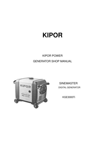
KIPORKIPOR POWERGENERATOR SHOP MANUALSINEMASTERDIGITAL GENERATORKGE3000Ti
PrefaceThis manual covers the construction, function and servicing procedure of the KIPOR KGE3500Ti andCoast Distribution model KGE3000Ti generators. This manual is principally concerned with thegenerator specifications, function, troubleshooting and repair. There is a separate manual to coverengine overhaul which includes the starting systems.Careful observance of the instructions contained in this manual will result in safe and quality servicework.All information, illustrations, directions and specifications included in this publication are based onthe latest product information available at the time of approval for printing.KIPOR POWER CO., LTD, reserves the right to make changes without incurring any obligationwhatever. No part of this publication may be reproduced without written permission.
Table of Contents1. Specifications .31.1 Specifications.31.2 Characteristics .41.3 Performance curves .72. Service information .82.1 The importance of proper service .82.2 Important safety precautions .82.3 Service rules .92.4 Electrical Precautions .92.5 Serial number location.102.6 Maintenance standards .112.7 Torque values .122.8 Troubleshooting .133. Maintenance .243.1 Regular inspection schedule .243.2 Engine oil .253.3 Inspection of engine alert switch .263.4 Air filter maintenance.273.5 Sparkplug service .283.6 Adjusting of valve clearance.303.7 Fuel filter and fuel switch maintenance .314. Air filter and Muffler .324.1 Air filter.324.2 Muffler .335. Carburetor.345.1 Carburetor removal and installation .345.2 Stepping Motor disassembly and reassembly .355.3 Carburetor disassembly and reassembly.366. Control panel, charging adjustor and inverter unit.386.1 Assembly and disassembly .386.2 Inspection.387. Housing group , fuel tank assembly and disassembly .418. Generator, ignition coil and trigger .428.1 Generator.428.2 ignition coil and trigger.43
1. SPECIFICATIONS1.1 SPECIFICATIONSDimensions and weightsModelKGE3000/3500TiLength27 in (686mm)Width16.7 in (425mm)Overall height19.9 in (495mm)Net weight132 lbs, 60 kgEngineModelKG205Type4-stroke,overhead valve, single cylinderDisplacement in (cc)12.0 (196)Bore x stroke in.(mm)2.68 x 2.13 (68 54)Horsepower4.0 @ 3600 rpmCompression ratio8.5:1Cooling systemForced airIgnition systemT.C.IIgnition timing25 B.T.D.CSpark plugF7RTCCarburetorFloat type, horizontal butterfly valveAir cleanerSemi-dryGovernorElectronic controlLubrication systemForced splashOil capacity.63 qt (0.6L)Fuel tank capacity3.43 gal (13L)Starting systemRecoil starter and Electrical starterStopping systemPrimary circuit groundFuelUnleaded gasoline 87 octane1
AlternatorModelKD 35Generator typeMulti pole rotation typeGenerator structureSelf-ventilation drip-proof typeExcitationSelf-excitation (Magnet type)Voltage regulation systemPWM(Plush width modulation)PhaseThree phaseRotating directionClockwise (Viewed from the generator)Frequency regulationAC-DC-AC conversion (Inverter type)1.2 CHARACTERISTICSModelKGE3000Ti/KGE3500TiMaximum output watts/amps3000/25 AmpsRated output watts/amps2800/23 AmpsRated frequency60 HZRated voltage AC120VDC Voltage/current12V/8.3 AmpsPower factor1.0cosφVoltage variation rate-Momentary10%max.Average1.5%max.Average time3 sec. max.Voltage stability 1%Frequency variation rate Momentary1%max.Average time1%max.1 sec. max.Frequency stability 0.1%Insulation resistance10MΩ min.AC circuit protector26A(120V)DC circuit protector14AOperating hours at rated load7 HoursNoise level dBA @ 23’ (7M)62 672
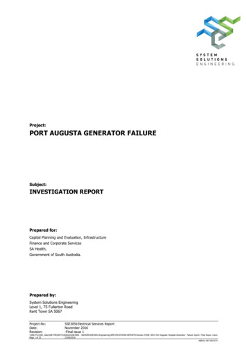
1.3PERFORMANCE CURVESAC output voltageThe curves show performance of the generator under average conditions.Performance may vary to some degree depending on ambient temperature and humidity.The output voltage will be higher than usual when the generator is still cold, immediately after theengine starts.AC external characteristic curve120110Current ( A) 0105152025DC output voltageDC external characteristic NAL DRAWING381012
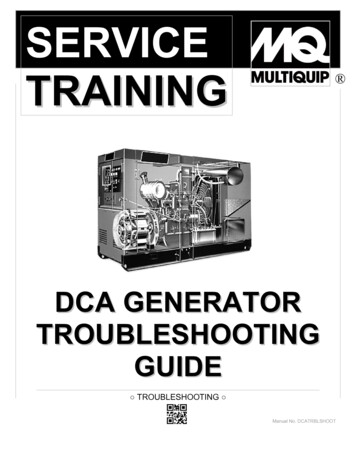
1.5WIRING DIAGRAMDC socketBlueBlueRedCharging windingBlueBlueRectifier wnBlackMain windingInverter unitstepping motorYellowOrangeSub windingBlueWhitePinkGreenOFFLow oil switchMTriggering windingDC contactorBlackStarting motorYellowWhite23ONSTART4BlackWhiteBrown Running IndicationGrayRedGreenOlivine Overload indicationYellowOrangeBlueLow oil gnition windingLock ofelectricaldoorChargingadjustor24V windingPurpleBlueHigh voltageunitWhitePurpleSingle phase socketOlivineGrayspark plugThrottle switchBlackRedOlivine415
2. Service information2.1The importance of proper servicingProper servicing is essential to the safety of the operator and the reliability of the generator. Anyerror or oversight made by the technician while servicing can easily result in faulty operation and/ordamage to the equipment or injury to the operator.WARNING Improper servicing can cause an unsafe condition that can lead to serious injury or death. Follow the procedures and precautions in this shop manual carefully.Some of the most important precautions are stated below.2.2 Important safety precautionsBe sure you have a clear understanding of all basic shop safety practices and that you are wearingappropriate clothing and safety equipment. When performing maintenance or repairs, be especiallycareful of the following:·Read the instructions before you begin, and be sure you have the tools and skills required toperform the tasks safely.·Be sure that the engine is off before you begin any maintenance or repairs. This will reducethe possibility of several hazards:- Carbon monoxide poisoning from engine exhaust.- Burns from hot parts.- Injury from moving parts.·Do not run the engine unless the instructions tell you to do so. Keep your hands and clothingaway from rotating parts.·To reduce the possibility of fire or explosion, exercise extreme caution when working aroundgasoline. Use only a nonflammable solvent, not gasoline, to clean parts. Keep cigarettes,sparks and flames away from all fuel-related parts.5
2.3 Service rules·Use genuine KIPOR or KIPOR-recommended parts and lubricants or their equivalents. Partsthat do not meet Kipor’s design specifications may damage the engine.·Use the special tools designed for the product.·Always install new gaskets, O-rings, etc. when reassembling components.·Clean parts in cleaning solvent upon disassembly. Lubricate any sliding surfaces beforereassembly. After reassembly, check all parts for proper installation and operation.·Many screws used in this machine are self-tapping. Be aware that cross-threading or overtightening these screws will strip the threads and ruin the hole.·Use only metric tools when servicing this engine. Metric bolts, nuts and screws are notinterchangeable with non metric fasteners. The use of incorrect tools and fasteners willdamage the engine.2.4Electrical precautions·Hold the connector body to disconnect the connector. Do not disconnect by pulling the wireharness. To disconnect the locking connector, be sure to unlock first, and then disconnect.·Check the connector terminals for bend, excessive extrusion, missing terminals, or otherabnormalities before connecting the connector.·To connect, insert the connector as far as it goes. If the connector is a locking type, be surethat it is locked securely.·Check the connector cover for breakage and check whether the connector female terminal isnot opened excessively. Then, connect the connector securely. Check the connector terminalfor rust. Remove the rust using an emery paper or equivalent material before connecting theconnector.·Set the harness clips in the specified places of the frame securely, and secure the wireharnesses.·Clamp the cables securely.6
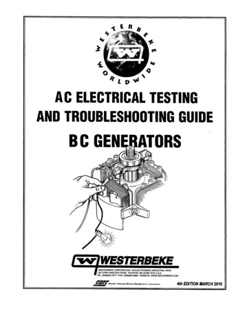
·Clamp the wire harnesses securely so that they do not interfere with the rotating parts,moving parts and hot parts.·Route and connect the wire harnesses properly. Be sure that the harnesses are not slack,twisted or pulled overly taut.·Route the wire harnesses properly so that they do not contact sharp edges and corners andthe end of the bolts and screws on the body.·If a wire harness must contact the end of the bolts or screws or sharp edges and corners,protect the contact part of the harness with a loom or by winding with electrical insulatingtape. If the wire harness has a grommet, set the grommet securely.·Take care not to pinch the wire harnesses during installation of a part. If a wire harness hasdamaged insulation, repair by winding with electrical insulating tape.·When using an electrical tester like a volt/ohm meter or clamp on meter, read themanufacturer’s operating instructions carefully before operating the tester. Be sure that thetester battery is fully charged and the meter is functioning properly2.5Serial number locationThe engine serial number is stamped at the underside of engine side cover. Refer to this numberwhen ordering or making technical inquiries.Engine serial numberEngine serial number7
2.6Maintenance standardsEnginePartItemStandard in. (mm)Service limitCylinderSleeve I.D.2.67 2.68 (68.02 68.04)2.68 (68.17)PistonSkirt O.D2.68 2.68 (67.97 67.99)2.68 (67.62)Piston-to-cylinder clearance.0016 .0023 (0.040 0.060).0047 (0.12)Pin bore I.D.18.002 18.00818.042O.D.708 .709 (17.990 18.000).709 (17.95)Pin-to-piston clearance.0001 .0071 (0.002 0.018).0003 (0.080)Ring width1.420 1.4401.32Piston pinPiston ringTopSecondConnecting rodCrankshaftValve1.420 1.4401.32Ring side clearance Top/second0.02 0.060.15Ring end clearance Top/second0.150 0.3501.0Small end I.D.7089 .7093 (18.006 18.017)0.711 (18.07)Big end I.D1.182 (30.015 30.025)1.184 (30.07)Big end oil clearance.0018 .0024 (0.046 0.060)0.12Big end side clearance.0177 .0276 (0.45 0.70).0394 (1.0)Crank pin O.D.29.960 29.97529.90Valve clearance Intake.0039 .0008 (0.10 0.02)Exhaust.0059 .0008 (0.15 0.02)Stem OD Intake.215 .216 (5.46 5.48).211 (5.35)Exhaust.215 (5.45 5.47).211 (5.35)Vessel I.D Intake/Exhaust.216-.217 (5.500 5.518).219 (5.56)Clearance of valve and vessel Intake.0008 .0023 (0.020 0.058).0039 (0.1)Exhaust.00 .0027 (030 0.068).0047 (.12)Seat width Intake/Exhaust.031 .047 (0.8 1.2).079 (2.0)Valve springFree Length Intake/Exhaust1.20 (30.5)1.14 (29)Cam wheelCam height Intake/Exhaust1.09 1.10 (27.63 27.91)1.08 (27.34)I.D (shaft bore)1.09 1.10 (27.68 27.94)1.08 (27.34)CamshaftO.D.550 .551 (13.966 13.984).553 (13.92)Valve lifterI.D (shaft bore).313 .314 (7.96 7.98).310 (7.87)Crankcase coverCamshaft BearingI.D.550 .552 (14.000 14.027).553 (14.05)Valve lifterI.D.315 .316 (8.000-8.015).317 (8.06)Camshaft BearingI.D.550 .552 (14.000-14.02)7.553 (14.05).024 .031 (0.6—0.8)—Primary side0.8—1.3Ω—Second side15—21kΩ—Cylinder blockSpark plugClearanceIgnition coilResistancePulse coilAir gap.020 .030 in.(Trigger)Resistance80 130Ω—Starting relayResistance3.8 4.1Ω—8(0.5 0.75)—
mitIgnition coilResistanceYellow/Green—Green0.26 0.28—Outer charging winding coilResistanceBlue-Blue0.12 0.15—Inner charging winding coilResistancePurple-purple0.19 0.21—Sub winding coilResistanceWhite—White0.12 0.14—Main winding coilResistanceBlack—Black0.8 1.1—2.7 Torque valuesItemThread dia. X pitchTightening torqueFt/lbfN.mConnecting rod boltM710.3 11.814 16Cylinder head boltM8 6020.7 23.628 32Spark plugM14 1.25 1918.4 22.225 30Crankcase coverM8 3014.75 17.020 23Flywheel nutM14 1.559.0 66.4280 90Tightening bolt of rocker arm baseM6 0.75 3314.75 17.020 23Adjusting nut of rocker axisM6 0.757.4 8.810 12M5 bolt、nut4.4 5.96 8M6 bolt、nut5.9 7.48 10M8 bolt、nut14.8 17.020 23M10 bolt、nut40.6 44.355 60Standard torqueNote:Use standard torque values for fasteners that are not listed in this table.9
2.8 TroubleshootingA. General symptoms and possible ontainsstaleDrain old fuel, clean and /or replacegasoline, or no fuel reaches carburetorEngine does notstart or hardstartingEngine speeddoes notFuel tank tube cloggedInspectFuel filter cloggedCleanCarburetor failureClean and/or replace*Spark plug cap disconnectedInstall securelyIgnition coil failureInspect and replaceSpark plug failureInspect and replaceOil level switch (Low oil alarm) failureInspect and replaceIgniting device failureInspect and replacePulse coil (Trigger) failureInspect and replaceChoke air inlet not controlled properlyThe position can be full open or half openCarburetor failureAdjust and/or disassemble and cleanThrottle control motor (stepping motor) failureInspectGenerator failureTroubleshootInverter unit failureTroubleshootValve clearance misadjustedAdjuststabilize, too highor too low* Carburetor replacement parts are not available. No adjustments or overhaul is permitted undercurrent EPA/CARB guidelines.10
B. Hard startingIf the engine does not start or is hard starting after reassembly, check to see whether the throttlevalve is at the full open position.Check the fuel level in the tankNo fuelAdd fuel and restart the engineSufficient fuelLoosen the drain screw andAbnormalCheck whether fuel reached thecarburetor, and check oil levelCheck for blockage of the fueltube, fuel filter or fuel pumpNormalDryWetPerform spark testNo spark orweak sparkClean the electrode and restart,taking care that the choke is notclosed too much. If flooding issevere, check the carburetorfloat valve.Perform the ignition systemtroubleshootingGood sparkInstall a compression gauge inthe spark plug hole and checkthe cylinder compression bypulling the recoil starter ropeseveral timesHigh cylinder Check for carbon deposits in thecompression combustion chamber.Low cylindercompressionNormal compression·Cylinder compression check1. Remove the spark plug cap and spark plug2. Install a compression gauge in the spark plug hole. Pull the recoil starter rope several timeswith force and measure the cylinder compression.Cylinder compression·0.45Mpa/600rpmIgnition system fault inspecting and repair- Spark Testa. Remove the spark plug.b. Install the spark plug onto spark plug cap.c. Turn the ignition switch of engine to the position” ON”. Then ground the spark electrode tothe cylinder head cover and pull the start motor rope to check if sparks jump across the11
electrode.!WarningWarning Do not pull the recoil starter rope while touching the high tension wire with a wet hand. Highvoltage is generated which is dangerous. Be sure to ground the spark plug and hold the plug capwith an insulated pair of pliers to perform the spark test. Make sure no spilled fuel is anywhere on the engine and no fuel is on the spark plug Keep sparks and any other combustible source away from the spark plug hole.C. Engine does not start with sufficient oil in the crankcase.No sparkGood sparkReplace the spark plugNo sparkGood sparkPerform test using a new portfireNo sparkDisconnect low oil alarm and perfomspark plug testNo sparkReplace the portfireGood sparkInspecting the resistance value ofalternator ignition coilNormalInspecting the resistance value and theclearance of triggerNormalReplace the ignition coilNormalInspecting and repair or replace12
D. Engine oil level is low, but engine does not stop.Drain all the oil, disconnect wire of lowoil alarm and measure linkage of Disconnectoutput of low oil alarm and the groundReplace the low oil alarmConnect the wire of low oil alarm Disconnectand disconnet portfire connectorplugs, then measure li nkage oforange wire and the groundConnectE. Engine starts but then stalls(throttle is installed in proper position)Oil alarmAdd oil and restartAdd Fuel and restartEnough fuelChokedUnchokedChokedClean or change the oilfeeding pipeUnchokedChokedDisassembly and cleanUnchokedAbnormalNormalMeasure compression of cylinderAbnormalNormalCheck clearance of triggerAbnormal1.Check if the clearanceof valve is proper.2.Check if it accumulatestoo much carbonincombustion chamber.3 .Ch eck abr asion ofpiston and piston ring andcylinder.Rearrange clearance oftrigger13
F. Engine speed does not increase or stabilize.Check the air cleanerCloggedClean the air cleanerNot cloggedCheck the valve clearanceAbnormalReadjust valve gapNormalAbnormal Clean electrodes and adjust thespark plug gap or replace a newspark plugNormalCheck for blockage of the main jet Cloggedand holes of carbunetorDisassemble and cleanNot cloggedAbnormalNormalAbnormalCheck the cylinder compressionNormalG. Smart throttle Problems1.Engine speed is too high, hunting or too low.Check the AC outputAbnormalNormalCheck control motor for throttlevalveAbnormalReplace the control motor forthrottle valveNormalReplace the inverter unit2. Smart Throttle system does not work under no load. (engine speed does increase after connectingload with Smart Throttle system ON.)Check the AC outputCheck the throttle control motorCheck the smart switchCheck each Smart place the invert unit14Perform "No or low AC output"roubleshootingReplace the throttle controlmotorReplace the smart switchRepair or replace the wireharness
H. No or Low AC outputIs the overload indicator light ON?ONDisconnect the load, andrestart the engine.OFFIs the engine speed normal?Engine speed:Smart switch ON: 3000 100rpmSmart switch OFF:3600 100rpmNormalEngine stopped and check ACreceptacleAbnormalAbnormalPerform the throttle controlsystem troubleshootingReplace the AC receptacleNormalDisconnect thr 6P connector fromthe invertrt unit. Pull the recoilstarter and measure the ACvoltage between the white andblack terminals Voltage:120V model:black — black: 30Vwhite — white: 1V230V/240V model:black — black: 60VWhite — white: 1AbnormalCheck and repair the harnessof stator or replace the stator.Magnetic force of the rotormagnet is low . Replace therototNormalReplace the inverter unit.The stator output may be checked with the engine running. Disconnect the 6P connector from theinverter unit. starting Check voltage between pins 1 & 4, pins 2 & 4, and pins 1 & 2. There shouldbe 280 to 330 Volts AC. If one or more of the three tests fail, the problem is either a damaged wireharness or a defective alternator.I. No DC outputIs the engine speed normal ?AbnormalEngine speed : 5500 100 min-1(rpm)(Smart switch OFF)NormalCheck the DC outputAbnormalPerform the throttle control systemtroubleshooting .Replace the DC receptacle .NormalAbnormalCheck the rectifierNormalMeasure the resistance between theblue DC coil terminals of the rectifier Abnormal4P connector.Resistance value:0.12 0.15ΩNormalRotor lose magnetism ,replace rotor15Rectifierrectifier.isfaulty.ReplacetheCheck the wire harness (input line )replace the stator .
J. Engine will not start ElectricallyMeasure the voltage ofaccumulatorAbnormalChange a new accumulatorNormalCheck the ignition switchAbnormalReplace the ignition switchNormalCheck the starting relayAbnormalReplace the starting relayNormalCheck the starting motorAbnormalReplace the starting motorNormalCheck , repair or changemain harness wireK. Starting Battery Will Not Hold a ChargeCheck ignition switchAbnormalReplace ignition coilNormalCheck charging adjustorAbnormalReplace charging adjustorNormalMeasure resistance value ofcharging windingResistance value:0.19 0.21ΩAbnormalCheck, repair wiring harness ofalternator and change statorNormalCheck, repair or change wiringharness16
3MAINTENANCE3.1Maintenance scheduleRegular service period①Each useFirstmonthor 10 Hrs.Item perform at every indicatedEvery3monthsor50Hrs.month or operating hour interval,Every6monthsorEvery year or300 Hrs.100 Hrs.whichever comes firstEngine OilCheck ReplaceAir cleanerCheck ②CleanSpark plugClean-Adjust Spark catcherClean Valve clearanceCheck-Adjust ③Fuel tank and filterClean ③Fuel lineCheckEvery 2 year (Replace if necessary③)Note:①Interval operating time in normal troubleshooting.②When it is used in dusty place, filter should be cleaned every 10 hours or everyday.③Maintenance should be carried out by the qualified technicians. 3.2 Engine oil3.2 Engine OilA. Checking Oil LevelEngine should be shut off and generator be on level ground when checking the oil level.(1) Remove the oil dipstick, check oil level.Upper limit17Lower limitScrew, the oil sticktightly, then unscrew it
(2) Add the proper viscosity engine oil to the upper limit if oil level is low. Be careful to over fill.B. Changing engine oil(1) Remove the oil dipstick and unscrew oil drain plug to drain used oil.(2) Replace the drain plug and secure tightly.(3) Add the proper viscosity oil to the upper oil limit level.(4) Reinstall the dipstick and screw it tightly3.3Inspection of the Oil Alert Switch(1) Disconnect the orange connection of the oil alert wire when engine is running, and ground oneend to the engine block as shown below to ensure that the engine will stop when the oil alert lamp islit.NOTE: On early models, the oil alert connection is in the back of the generator on the opposite sideof the service door.Lead of ignitorLead of oil alarm18Ground through the caseof engine
(3) Stop the engine and disconnect the orange wire of the oil alert after insuring that the engine oil isat the proper level. Test the conductivity between the end shown in the figure and the case of engine,No conductivity indicates a normal condition.Lead of ignitorLead of oil alarm(4) Drain all the engine oil in the engine repeat the test. The switch is working properly if there isnormal conductivity.3.4Air Filter Maintenance(1) Open the service door.(2) Open the cover of air filter and take out the filter element.(3) Blow the inner side of filter element using compressed air or lightly knock it to remove dirt. If anydirt remains, change the element. Be sure to use a genuine Kipor element to maintain a proper sealand avoid engine damage.(4) Reinstall the filter element and close the service door.Filter elementsubassemblyAir filter coverBlow the innerr side ofair filter element usingthe compressed air19
Attention Don’t operate the generator without the filter element in place or serious engine damage mayresult.3.5Spark Plug Servicing(1) Remove the spark plug cap, and use a spark plug wrench to remove the spark plug.(2) Check the condition of the porcelain insulator. Replace the spark plug if it is chipped or cracked.(3) Remove carbon or other deposits with a stiff wire brush. Check if the sealing washer is damaged.(4) Check the resistance of the spark plug and replace it if it is not within the specified resistancevalue.Resistance of spark plug3 9KΩ(5) Use a feeler gauge to check the electrode gap. Adjust the electrode to the followingspecification by carefully bending the side electrode to the specified value.Clearance of spark plug.024 .031 in 0.6 0.8mmStandard spark plugF7RTC0.6-0.820
(6) Reinstall the spark plug and screw it tightly after regulating, the specified torque is 18.44 22.13 ftlbs. (25 30 N.m).3.6Adjusting valve clearanceAttentionValve adjustment should only be performed on a cool engine.(1) Remove valve cover.Gasket of cylinder head covercylinder head cover(2) Pull the starter rope gently and set the piston in top dead center (the scale of starting wheelshould align with the sign “ ” on the air guiding cover)markscale(3) Insert a feeler gauge into the gap between rocker and valve to measure the valve clearance.Valve ClearanceIntake: 0039 .0008 in (0.10 0.02mm)Exhaust:.0059 .0008 in (0.15 0.02mm)21
(4) If adjustment is necessary, proceed as follows:a. Hold rocker axis using the wrench and loosen the lock nut.b. Loosen the lock nut of rocker axis to gain the specified intake and exhaust valve clearance.c. Hold rocker axis using a wrench and tighten the lock nut.d. Check the clearance of valve after adjustment.3.7 Fuel filter and fuel switch maintenanceFuel tankFilter seal cushionFuel elementFuel switchAttention Keep smoking materials and any open flames away during fuel system maintenance. Make sure that there is no leaking fuel after service.(1) Drain all fuel from the tank and carburetor and remove the fuel tank.(2) Loosen the nuts between fuel switch and fuel tank and remove the filter element.(3) Turn the fuel switch to the open position. Clean it with a suitable solvent then blow dry withcompressed air.(4) Remove any foreign material from the fuel filter and insure the filter net is undamaged. Replace ifnecessary(5) Properly install seal cushion and filter element and tighten the nuts between fuel switch and thefuel tank.22
4.Air Filter and Muffler4.1 Air filter Disassembly and assemblyBottom case of air filterFilter elementAir filter coverCarburetorInstall:make sure that gaskets have nodamages and bendings and payattention to inner and outer sides.4.2Muffler Disassembly and assemblyMuffler syphonassembly:Clean the carboninside muffler syphonusing the brushbefore installingFireproofing capassembly:Clean the carbon usingthe brush before installingExhaust pipe gasketMuffler gasketCover ofmufflerMufflerassembly:knock it to remove carboninside by using rubberhammer before installing.23
5.CarburetorAttention Loosen the gasoline drain bolts before disassembly to drain fuel in the carburetor. Smoking and any source of combustion are strictly forbidden in the process of disassembly.5.1Carburetor removal and installationCarburetor gasket AReassembly:Check if there is anydamage in the gasketbefore assemblyRope of air chokeAir choke weldmentAir intake pipe gasketReassembly:Check if there is anydamage in the gasketbefore assemblyGasket ofcarburetorCarburetorInsulator block ofassemblycarburetorReassembly:Carburetor gasket BCheck if there is anyReassembly:damage in the insulatorCheck if there is anyblock before assembly.damage in the gasketbefore assembly24Air filter bottom caseFilter elementAir filter cover
5.2Stepping motor disassembly and reassemblystepping motorstepping motor baseforkfork springdisassembly :hold it tightly for fear that the springwill lose when it is disassemblied .fork springfuel controlleverfork25
5.3Carburetor disassembly and reassemblyNOTE: With the exception of changing the main jet, no adjustments, modifications, or other maintenance is permittedon EPA and CARB certified engines. This includes any Kipor generator ever sold in North America. This drawing is forinformation only.Air stroke rodForkFork springAssembly of acceleratorGasket of air strokeRestoratingspring of airchokeAccelerator pieceAdjusting screw ofthe mixture ratioGasketIdle adjusting screwReassembly:Inspect the abrasion of thefront head,then install it.Stopper ofchannelMain n
· Use genuine KIPOR or KIPOR-recommended parts and lubricants or their equivalents. Parts that do not meet Kipor ’s design specifications may damage the engine. · Use the special tools designed for the product. · Always install new gaskets, O-rings, etc. when reassembling components. · Clean parts in cleaning solvent upon disassembly.File Size: 1MB