Transcription
DOE FundamentalsMECHANICAL SCIENCEModule 1Diesel Engine Fundamentals
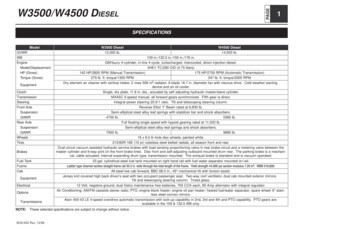
Mechanical ScienceDiesel Engine FundamentalsTABLE OF CONTENTSTABLE OF CONTENTS . iiLIST OF FIGURES . ivLIST OF TABLES. viREFERENCES . viiOBJECTIVES . viiiDIESEL ENGINES . 1Introduction . 1History . 2Diesel Engines . 2Major Components of a Diesel Engine. 3The Cylinder Block . 5Crankcase and Oil Pan . 6Cylinder Sleeve or Bore . 6Piston and Piston Rings . 7Connecting Rod. 7Crankshaft . 7Flywheel . 8Cylinder Heads and Valves . 9Timing Gears, Camshaft, and Valve Mechanism . 9Blower .11Diesel Engine Support Systems .11Exhaust System .15Operational Terminology .15Bore and Stroke .15Summary .17FUNDAMENTALS OF THE DIESEL CYCLE .18The Basic Diesel Cycles .18The Four-Stoke Cycle .19The Two-Stroke Cycle .22Summary .24MS-01-ii
Mechanical ScienceDiesel Engine FundamentalsDIESEL ENGINE SPEED, FUEL CONTROLS, AND PROTECTION .26Engine Control.26Fuel Injectors .26Governor .29Operation of a Governor .30Starting Circuits .32Engine Protection .33Summary .35MS-01-iii
Mechanical ScienceDiesel Engine FundamentalsLIST OF FIGURESFigure 1 Example of a Large Skid-Mounted, Diesel-Driven Generator . 2Figure 2 Cutaway of a Four-Stroke Supercharged Diesel Engine . 4Figure 3 Cross Section of a V-type Four Stroke Diesel Engine . 5Figure 4 The Cylinder Block . 5Figure 5 Diesel Engine Wet Cylinder Sleeve . 6Figure 6 Piston and Piston Rod . 7Figure 7 Diesel Engine Crankshaft and Bearings . 8Figure 8 Diesel Engine Valve . 9Figure 9 Diesel Engine Camshaft and Drive Gear . 9Figure 10 Diesel Engine Valve Train . 10Figure 11 Diesel Engine Cooling System . 11Figure 12 Diesel Engine Internal Lubrication System . 12Figure 13 Diesel Engine Fuel Flowpath . 13Figure 14 Oil Bath Air Filter . 14Figure 15 Compression Ratio . 16Figure 16 Scavenging and Intake . 19Figure 17 Compression . 20Figure 18 Fuel Injection . 20Figure 19 Power. 21Figure 20 Exhaust . 21Figure 21 2-Stroke Exhaust . 22Figure 22 2-Stroke Intake . 22Figure 23 2-Stroke Compression . 23Figure 24 2-Stroke Fuel Injection . 23Figure 25 2-Stroke Power . 23MS-01-iv
Mechanical ScienceDiesel Engine FundamentalsFigure 26 Fuel Injector Cutaway . 27Figure 27 Fuel Injector Plunger . 28Figure 28 Simplified Mechanical-Hydraulic Governor . 30Figure 29 Cutaway of a Woodward Governor . 31MS-01-v
Mechanical ScienceDiesel Engine FundamentalsLIST OF TABLESNONEMS-01-vi
Mechanical ScienceDiesel Engine FundamentalsREFERENCES Benson & Whitehouse, Internal Combustion Engines, Pergamon. Cheremisinoff, N. P., Fluid Flow, Pumps, Pipes and Channels, Ann Arbor Science. Scheel, Gas and Air Compression Machinery, McGraw/Hill. Skrotzki and Vopat, Steam and Gas Turbines, McGraw/Hill. Stinson, Karl W., Diesel Engineering Handbook, Diesel Publications Incorporated.MS-01-vii
Mechanical ScienceDiesel Engine FundamentalsOBJECTIVESTERMINAL OBJECTIVE1.0Without references, DESCRIBE the components and theory of operation for a dieselengine.ENABLING OBJECTIVES1.1DEFINE the following diesel engine terms:a. Compression ratiob. Borec. Stroked. Combustion chamber1.2Given a drawing of a diesel engine, IDENTIFY the following:a. Piston/rode.Intake ports or valve(s)b. Cylinderf.Exhaust ports or valve(s)c. Blowerg.Fuel injectord. Crankshaft1.3EXPLAIN how a diesel engine converts the chemical energy stored in the diesel fuel intomechanical energy.1.4EXPLAIN how the ignition process occurs in a diesel engine.1.5EXPLAIN the operation of a 4-cycle diesel engine to include when the following eventsoccur during a cycle:a. Intaked.Compressionb. Exhauste.Powerc. Fuel injection1.6EXPLAIN the operation of a 2-cycle diesel engine, including when the following eventsoccur during a cycle:a. Intaked.Compressionb. Exhauste.Powerc. Fuel injection1.7DESCRIBE how the mechanical-hydraulic governor on a diesel engine controls enginespeed.1.8LIST five protective alarms usually found on mid-sized and larger diesel engines.MS-01-viii
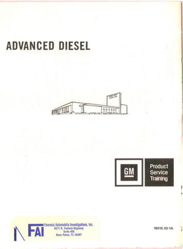
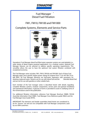
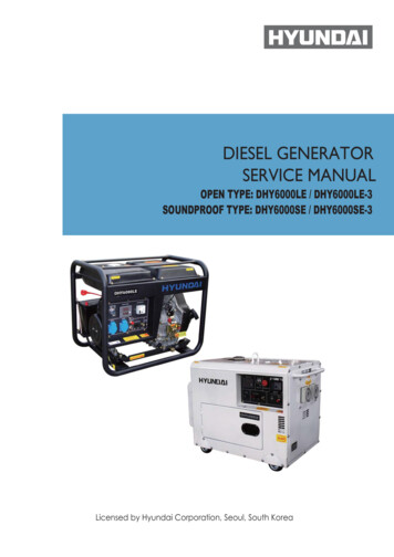
Mechanical ScienceDiesel Engine FundamentalsDIESEL ENGINESOne of the most common prime movers is the diesel engine. Before gaining anunderstanding of how the engine operates a basic understanding of the engine'scomponents should be gained. This chapter reviews the major components of ageneric diesel engine.EO 1.1DEFINE the following diesel engine terms:a. Compression ratiob. Borec. Stroked. Combustion chamberEO 1.2Given a drawing of a diesel engine, IDENTIFY the fte.f.g.Intake ports or valve(s)Exhaust ports or valve(s)Fuel injectorIntroductionMost DOE facilities require some type of prime mover to supply mechanical power for pumping,electrical power generation, operation of heavy equipment, and to act as a backup electricalgenerator for emergency use during the loss of the normal power source. Although severaltypes of prime movers are available (gasoline engines, steam and gas turbines), the dieselengine is the most commonly used. Diesel engines provide a self-reliant energy source that isavailable in sizes from a few horsepower to 10,000 hp. Figure 1 provides an illustration of acommon skid-mounted, diesel-driven generator. Relatively speaking, diesel engines are small,inexpensive, powerful, fuel efficient, and extremely reliable if maintained properly.Because of the widespread use of diesel engines at DOE facilities, a basic understanding of theoperation of a diesel engine will help ensure they are operated and maintained properly. Due tothe large variety of sizes, brands, and types of engines in service, this module is intended toprovide the fundamentals and theory of operation of a diesel engine. Specific information on aparticular engine should be obtained from the vendor's manual.MS-01-1
Mechanical ScienceDiesel Engine FundamentalsFigure 1 Example of a Large Skid-Mounted, Diesel-Driven GeneratorHistoryThe modern diesel engine came about as the result of the internal combustion principles firstproposed by Sadi Carnot in the early 19th century. Dr. Rudolf Diesel applied Sadi Carnot'sprinciples into a patented cycle or method of combustion that has become known as the "diesel"cycle. His patented engine operated when the heat generated during the compression of the airfuel charge caused ignition of the mixture, which then expanded at a constant pressure duringthe full power stroke of the engine.Dr. Diesel's first engine ran on coal dust and used a compression pressure of 1500 psi toincrease its theoretical efficiency. Also, his first engine did not have provisions for any type ofcooling system. Consequently, between the extreme pressure and the lack of cooling, theengine exploded and almost killed its inventor. After recovering from his injuries, Diesel triedagain using oil as the fuel, adding a cooling water jacket around the cylinder, and lowering thecompression pressure to approximately 550 psi. This combination eventually proved successful.Production rights to the engine were sold to Adolphus Bush, who built the first diesel engines forcommercial use, installing them in his St. Louis brewery to drive various pumps.Diesel EnginesA diesel engine is similar to the gasoline engine used in most cars. Both engines are internalcombustion engines, meaning they burn the fuel-air mixture within the cylinders. Both arereciprocating engines, being driven by pistons moving laterally in two directions. The majority oftheir parts are similar. Although a diesel engine and gasoline engine operate with similarcomponents, a diesel engine, when compared to a gasoline engine of equal horsepower, isheavier due to stronger, heavier materials used to withstand the greater dynamic forces fromthe higher combustion pressures present in the diesel engine.MS-01-2
Mechanical ScienceDiesel Engine FundamentalsThe greater combustion pressure is the result of the higher compression ratio used by dieselengines. The compression ratio is a measure of how much the engine compresses the gassesin the engine's cylinder. In a gasoline engine the compression ratio (which controls thecompression temperature) is limited by the air-fuel mixture entering the cylinders. The lowerignition temperature of gasoline will cause it to ignite (burn) at a compression ratio of less than10:1. The average car has a 7:1 compression ratio. In a diesel engine, compression ratiosranging from 14:1 to as high as 24:1 are commonly used. The higher compression ratios arepossible because only air is compressed, and then the fuel is injected. This is one of the factorsthat allows the diesel engine to be so efficient. Compression ratio will be discussed in greaterdetail later in this module.Another difference between a gasoline engine and a diesel engine is the manner in whichengine speed is controlled. In any engine, speed (or power) is a direct function of the amount offuel burned in the cylinders. Gasoline engines are self-speed-limiting, due to the method theengine uses to control the amount of air entering the engine. Engine speed is indirectlycontrolled by the butterfly valve in the carburetor. The butterfly valve in a carburetor limits theamount of air entering the engine. In a carburetor, the rate of air flow dictates the amount ofgasoline that will be mixed with the air. Limiting the amount of air entering the engine limits theamount of fuel entering the engine, and, therefore, limits the speed of the engine. By limiting theamount of air entering the engine, adding more fuel does not increase engine speed beyond thepoint where the fuel burns 100% of the available air (oxygen).Diesel engines are not self-speed-limiting because the air (oxygen) entering the engine isalways the maximum amount. Therefore, the engine speed is limited solely by the amount offuel injected into the engine cylinders. Therefore, the engine always has sufficient oxygen toburn and the engine will attempt to accelerate to meet the new fuel injection rate. Because ofthis, a manual fuel control is not possible because these engines, in an unloaded condition, canaccelerate at a rate of more than 2000 revolutions per second. Diesel engines require a speedlimiter, commonly called the governor, to control the amount of fuel being injected into theengine.Unlike a gasoline engine, a diesel engine does not require an ignition system because in adiesel engine the fuel is injected into the cylinder as the piston comes to the top of itscompression stroke. When fuel is injected, it vaporizes and ignites due to the heat created bythe compression of the air in the cylinder.Major Components of a Diesel EngineTo understand how a diesel engine operates, an understanding of the major components andhow they work together is necessary. Figure 2 is an example of a medium-sized, four-stroke,supercharged, diesel engine with inlet ports and exhaust valves. Figure 3 provides a crosssection of a similarly sized V-type diesel engine.MS-01-3
Mechanical ScienceDiesel Engine FundamentalsFigure 2 Cutaway of a GM V-16 Four-Stroke Supercharged Diesel EngineMS-01-4
Mechanical ScienceDiesel Engine FundamentalsFigure 3 Cross Section of a V-typeFour Stroke Diesel EngineThe Cylinder BlockThe cylinder block, as shown inFigure 4, is generally a single unitmade from cast iron. In a liquidcooled diesel, the block alsoprovides the structure and rigidframe for the engine's cylinders,water coolant and oil passages,and support for the crankshaft andcamshaft bearings.Figure 4 The Cylinder BlockMS-01-5
Mechanical ScienceDiesel Engine FundamentalsCrankcase and Oil PanThe crankcase is usually located on the bottom of the cylinder block. The crankcase is definedas the area around the crankshaft and crankshaft bearings. This area encloses the rotatingcrankshaft and crankshaft counter weights and directs returning oil into the oil pan. The oil panis located at the bottom of the crankcase as shown in Figure 2 and Figure 3. The oil pan collectsand stores the engine's supply of lubricating oil. Large diesel engines may have the oil pandivided into several separate pans.Cylinder Sleeve or BoreDiesel engines use one of two types of cylinders. In one type, each cylinder is simply machinedor bored into the block casting, making the block and cylinders an integral part. In the secondtype, a machined steel sleeve is pressed into the block casting to form the cylinder. Figure 2and Figure 3 provide examples of sleeved diesel engines. With either method, the cylindersleeve or bore provides the engine with the cylindrical structure needed to confine thecombustion gasses and to act as a guide for the engine's pistons.In engines using sleeves, there are twotypes of sleeves, wet and dry. A dry sleeveis surrounded by the metal of the block anddoes not come in direct contact with theengine's coolant (water). A wet sleevecomes in direct contact with the engine'scoolant. Figure 5 provides an example of awet sleeve. The volume enclosed by thesleeve or bore is called the combustionchamber and is the space where the fuel isburned.In either type of cylinder, sleeved or bored,the diameter of the cylinder is called thebore of the engine and is stated in inches.For example, the bore of a 350 cubic inchChevrolet gasoline engine is 4 inches.Figure 5 Diesel Engine Wet Cylinder SleeveMost diesel engines are multi-cylinder engines and typically have their cylinders arranged in oneof two ways, an in-line or a "V", although other combinations exits. In an in-line engine, as thename indicates, all the cylinders are in a row. In a "V" type engine the cylinders are arranged intwo rows of cylinders set at an angle to each other that align to a common crankshaft. Eachgroup of cylinders making up one side of the "V" is referred to as a bank of cylinders.MS-01-6
Mechanical ScienceDiesel Engine FundamentalsPiston and Piston RingsThe piston transforms the energy of theexpanding gasses into mechanical energy.The piston rides in the cylinder liner orsleeve as shown in Figure 2 and Figure 3.Pistons are commonly made of aluminum orcast iron alloys.To prevent the combustion gasses frombypassing the piston and to keep friction toa minimum, each piston has several metalrings around it, as illustrated by Figure 6.Figure 6 Piston and Piston RodThese rings function as the seal between the piston and the cylinder wall and also act to reducefriction by minimizing the contact area between the piston and the cylinder wall. The rings areusually made of cast iron and coated with chrome or molybdenum. Most diesel engine pistonshave several rings, usually 2 to 5, with each ring performing a distinct function. The top ring(s)acts primarily as the pressure seal. The intermediate ring(s) acts as a wiper ring to remove andcontrol the amount of oil film on the cylinder walls. The bottom ring(s) is an oiler ring andensures that a supply of lubricating oil is evenly deposited on the cylinder walls.Connecting RodThe connecting rod connects the piston to the crankshaft. See Figure 2 and Figure 3 for thelocation of the connecting rods in an engine. The rods are made from drop-forged, heat-treatedsteel to provide the required strength. Each end of the rod is bored, with the smaller top boreconnecting to the piston pin (wrist pin) in the piston as shown in Figure 6. The large bore end ofthe rod is split in half and bolted to allow the rod to be attached to the crankshaft. Some dieselengine connecting rods are drilled down the center to allow oil to travel up from the crankshaftand into the piston pin and piston for lubrication.A variation found in V-type engines that affects the connecting rods is to position the cylinders inthe left and right banks directly opposite each other instead of staggered (most commonconfiguration). This arrangement requires that the connecting rods of two opposing cylindersshare the same main journal bearing on the crankshaft. To allow this configuration, one of theconnecting rods must be split or forked around the other.CrankshaftThe crankshaft transforms the linear motion of the pistons into a rotational motion that istransmitted to the load. Crankshafts are made of forged steel. The forged crankshaft ismachined to produce the crankshaft bearing and connecting rod bearing surfaces. The rodMS-01-7
Mechanical ScienceDiesel Engine Fundamentalsbearings are eccentric, or offset, from the center of the crankshaft as illustrated in Figure 7. Thisoffset converts the reciprocating (up and down) motion of the piston into the rotary motion of thecrankshaft. The amount of offset determines the stroke (distance the piston travels) of theengine (discussed later).The crankshaft does not ride directly on the cast iron block crankshaft supports, but rides onspecial bearing material as shown in Figure 7. The connecting rods also have bearings insertedbetween the crankshaft and the connecting rods. The bearing material is a soft alloy of metalsthat provides a replaceable wear surface and prevents galling between two similar metals (i.e.,crankshaft and connecting rod). Each bearing is split into halves to allow assembly of theengine. The crankshaft is drilled with oil passages that allow the engine to feed oil to each of thecrankshaft bearings and connection rod bearings and up into the connecting rod itself.The crankshaft has large weights, called counter weights, that balance the weight of theconnecting rods. These weights ensure an even (balance) force during the rotation of themoving parts.Figure 7 Diesel Engine Crankshaft and BearingsFlywheelThe flywheel is located on one end of the crankshaft and serves three purposes. First, throughits inertia, it reduces vibration by smoothing out the power stroke as each cylinder fires. Second,it is the mounting surface used to bolt the engine up to its load. Third, on some diesels, theflywheel has gear teeth around its perimeter that allow the starting motors to engage and crankthe diesel.MS-01-8
Mechanical ScienceDiesel Engine FundamentalsCylinder Heads and ValvesA diesel engine's cylinder heads perform several functions. First, they provide the top seal forthe cylinder bore or sleeve. Second, they provide the structure holding exhaust valves (andintake valves where applicable), the fuel injector, and necessary linkages. A diesel engine'sheads are manufactured in one of two ways. In one method, each cylinder has its own headcasting, which is bolted to the block. This method is used primarily on the larger diesel engines.In the second method, which is used onsmaller engines, the engine's head is cast asone piece (multi-cylinder head).Diesel engines have two methods of admittingand exhausting gasses from the cylinder. Theycan use either ports or valves or acombination of both. Ports are slots in thecylinder walls located in the lower 1/3 of thebore. See Figure 2 and Figure 3 for examplesof intake ports, and note their relative locationwith respect to the rest of the engine. Whenthe piston travels below the level of the ports,the ports are "opened" and fresh air or exhaustgasses are able to enter or leave, dependingon the type of port.Figure 8 Diesel Engine ValveThe ports are then "closed" whenthe piston travels back above thelevel of the ports. Valves (refer tofigure 8) are mechanicallyopened and closed to admit orexhaust the gasses as needed.The valves are located in thehead casting of the engine. Thepoint at which the valve sealsagainst the head is called thevalve seat. Most medium-sizeddiesels have either intake portsor exhaust valves or both intakeand exhaust valves.Timing Gears, Camshaft, andValve MechanismFigure 9 Diesel Engine Camshaft and Drive GearIn order for a diesel engine tooperate, all of its components must perform their functions at very precise intervals in relation tothe motion of the piston. To accomplish this, a component called a camshaft is used. Figure 9MS-01-9
Mechanical ScienceDiesel Engine Fundamentalsillustrates a camshaft and camshaft drive gear. Figure 2 and Figure 3 illustrate the location of acamshaft in a large overhead cam diesel engine.A camshaft is a long bar with egg-shaped eccentric lobes, one lobe for each valve and fuelinjector (discussed later). Each lobe has a follower as shown on Figure 10. As the camshaft isrotated, the follower is forced up and down as it follows the profile of the cam lobe. Thefollowers are connected to the engine's valves and fuel injectors through various types oflinkages called pushrods and rocker arms. The pushrods and rocker arms transfer thereciprocating motion generated by the camshaft lobes to the valves and injectors, opening andclosing them as needed. The valves are maintained closed by springs.As the valve is opened by the camshaft, it compresses the valve spring. The energy stored inthe valve spring is then used to close the valve as the camshaft lobe rotates out from under thefollower. Because an engine experiences fairly large changes in temperature (e.g., ambient to anormal running temperature of about 190 F), its components must be designed to allow forthermal expansion. Therefore, the valves, valve pushrods, and rocker arms must have somemethod of allowing for the expansion. This is accomplished by the use of valve lash. Valve lashis the term given to the "slop" or "give" in the valve train before the cam actually starts to openthe valve.The camshaft is driven by the engine'scrankshaft through a series of gearscalled idler gears and timing gears.The gears allow the rotation of thecamshaft to correspond or be in timewith, the rotation of the crankshaft andthereby allows the valve opening,valve closing, and injection of fuel tobe timed to occur at precise intervalsin the piston's travel. To increase theflexibility in timing the valve opening,valve closing, and injection of fuel,and to increase power or to reducecost, an engine may have one ormore camshafts. Typically, in amedium to large V-type engine, eachbank will have one or more camshaftsper head. In the larger engines, theintake valves, exhaust valves, andfuel injectors may share a commoncamshaft or have independent camshafts.Figure 10 Diesel Engine Valve TrainDepending on the type and make of the engine, the location of the camshaft or shafts varies.The camshaft(s) in an in-line engine is usually found either in the head of the engine or in thetop of the block running down one side of the cylinder bank. Figure 10 provides an example ofMS-01-10
Mechanical ScienceDiesel Engine Fundamentalsan engine with the camshaft located on the side of the engine. Figure 3 provides an example ofan overhead cam arrangement as on a V-type engine. On small or mid-sized V-type engines,the camshaft is usually located in the block at the center of the "V" between the two banks ofcylinders. In larger or multi-camshafted V-type engines, the camshafts are usually located in theheads.BlowerThe diesel engine's blower is part of the air intake system and serves to compress the incomingfresh air for delivery to the cylinders for combustion. The location of the blower is shown onFigure 2. The blower can be part of either a turbocharged or supercharged air intake system.Additional information on these two types of blowers is provided later in this module.Diesel Engine Support SystemsA diesel engine requires five supporting systems in order to operate: cooling, lubrication, fuelinjection, air intake, and exhaust. Depending on the size, power, and application o
Mechanical Science Diesel Engine Fundamentals MS-01-2 Figure 1 Example of a Large Skid-Mounted, Diesel-Driven Generator History The modern diesel engine came about