Transcription
IG6000IG6000hGenerator Service ManualKipor Power Systems August 1, 2011
PrefaceThis manual covers the construction, function and servicing procedure of the KIPOR KGE7000Ti singlevoltage generator and the dual voltage KGE6000Ti and IG6000 generator. This manual covers generatorspecifications, function, troubleshooting and repair.Careful observance of the instructions contained in this manual will result in safe and quality servicework.All information, illustrations, directions and specifications included in this publication are based on thelatest product information available at the time of printing.KIPOR POWER CO., LTD, reserves the right to make changes without incurring any obligation whatever.No part of this publication can be reproduced without written permission.
TABLE of CONTENTS1. Specifications.1.1 General Specifications.1.2 Generator Specifications.1.3 Performance Curves.1.4 Dimensional drawings.1 .5 W i ri n g D i a g ra m . . . . . . . . . . . . . . . . . . . . . . . . . . . . . . . . . . . . . . . . . . . . . . . . . . . . . . . . . . . . . . . . . .2. Service and Maintenance .2.1 The Importance of Proper Service . .2.2 Safety Precautions . .2.3 Service Rules.2.4 Serial Number and Bar Code Location. .2.5 Engine Service Standards.2.6 Fastening Torques . .2.7 Troubleshooting. .3. Inspection and Adjustment.3.1 Maintenance Schedule.3.2 Engine Oil.3.3 Low Oil alarm .3.4 Air Cleaner.3.5 Spark Plug.3.6 Valve Clearance. .3.7 Fuel Switch/Fuel Filter.4. Air Cleaner/Muffler.4.1 Air Cleaner.4.2 Muffler.4.3 Air vent pipe and second gulp valve 5. Carburetor .5.1 Disassembly and Reassembly.5.2 Inspection. . . . . . . . . . . . . . . . . . . . . .6. Control Panel, charging adjustor, timing relay, Ignition control module, inverter Module.6.1 Disassembly and Reassembly.6.2 Inspection.7. Housing group and Fuel Tank.7.1 Disassembly and Reassembly (IG6000).7.2 Disassembly and Reassembly(IG6000h).7.3 Vaporize control system .8. Alternator, Ignition Coil, Trigger, electric motor, air guide cover.8.1 Air guide cover, cylinder end cover, cylinder bottom cover air guide plate, electric motor.8.2 Ignition Coil and Trigger.8.3 Alternator.9. Cylinder cover, valve.9.1 Disassembly and Reassembly.9.2 Inspection.10. Crankcase cover, Crankshaft, Camshaft, Piston, Connecting rod.10.1 Disassembly and Reassembly.10.2 Inspection.1
1.SPECIFICATIONS and DIAGRAMS1.1 General SpecificationsDimensions and weightsModelIG6000Overall length- in. (mm)31.6 (802)Overall width- in. (mm)19.4 (498)Overall height- in. (mm)24.6 (624)Dry weight- lbs. (Kg)213 (96.7)EngineModelKG390GETiType4-stroke,OHV, single cylinderDisplacement- cu.in. (cc)23.7 (389)Bore x stroke- in. (mm)3.46 x 2.51 (88 64)Maximum horsepower(KVA)7.7/3600Compression ratio8.5:1Cooling systemForced airIgnition systemTransistorized controlled ignitionIgnition timing25 B.T.D.CSpark plugWR7DCCarburetorHorizontal float & fly typeAir cleanerDry replaceable elementGovernorInverter module controlLubrication systemForced splashOil capacity- qt. (L)1.2 (1.1)Starting systemElectric starterStopping systemElectric groundFuelAutomotive unleaded gasolineGeneratorModelKD70Generator typeMulti pole rotation typeGenerator structureSelf-ventilation drip-proof typeExcitationSelf-excitation (Magnet type)Voltage regulation systemPulse Width ModulationPhaseSingle phaseRotating directionClockwise (Viewed from the generator)Frequency regulationAC-DC-AC conversion (Inverter type)2
1.2 Generator SpecificationsModelIG6000Maximum output(AC)6.0 KVARated output (AC)5.5 KVARated frequency (HZ)60Rated voltage(AC)120/240Maximum current (amp)50/25Rated current(amp)45.8/22.9Rated voltage(DC)12VRated current(DC)5APower factor1.0Voltage e timeMax. 3 secondsVoltage stabilityFrequencyvariation rate 1%MomentaryMax. 1%AverageMax. 1%Average timeMax. 1secondFrequency stability 0.1%Insulation resistanceMin. 10MΩAC circuit protector- Amps 120/240 VAC51.7/25.8DC circuit protector7AFuel tank capacity- gal (L)5.4 (20)Operating hours at rated load5.5Noise level dB @23’ (7 m) no load-full load65-753
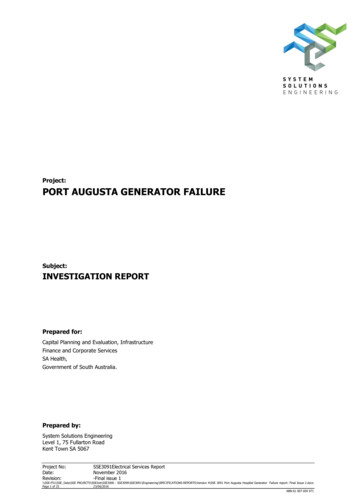
1.3 PERFORMANCE CURVESThe curves show performance of the generator under average conditions. Performance may varydepending upon ambient temperature, altitude and humidity. AC External characteristic curves DC External characteristic curves4
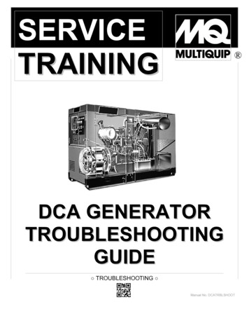
1.5 Wiring Diagrama. Single voltage output5
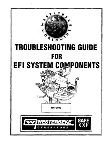
b. Double-voltage output6
2. SERVICE and MAINTENANCE2.1 The importance of proper servicingProper servicing is essential to the safety of the operator and the reliability of the generator. Any erroror oversight made by the technician while servicing can easily result in faulty operation and/or damage tothe equipment or injury to the operator.Warning!Improper servicing can cause an unsafe condition that can lead to serious injury or death.Follow the procedures and precautions in this shop manual carefully.Some of the most important precautions are stated below. But we could not list all the potential danger,you should judge yourself if it need to do the maintenance task.Warning!Could not follow the maintenance instruction and safety precautions can cause an unsafe condition thatcan lead to serious injury or death. Follow the procedures and precautions in this shop manual carefully.2.2 Safety PrecautionsBe sure you have a clear understanding of all basic shop safety practices and that you are wearingappropriate clothing and safety equipment. When performing maintenance or repairs, be especiallycareful of the following: Read the instructions before you begin, and be sure you have the tools and skills required toperform the tasks safely. Be sure that the engine is off before you begin any maintenance or repairs. This will reduce thepossibility of several hazards:- Carbon monoxide poisoning from engine exhaust.- Run engine in the ventilated place whenever.- Burns from hot parts.-Touch the engine parts after it cooled.- Injury from moving parts. Do not run the engine unless the instructions tell you to do so. Keep your handsand clothing away from rotating parts. To reduce the possibility of fire or explosion, exercise extreme caution whenworking around gasoline. Use only a nonflammable solvent, not gasoline, to cleanparts. Keep cigarettes, sparks and flames away from all fuel-related parts.7
2.3Service Rules Use genuine KIPOR or KIPOR recommended parts and lubricants or their equivalents. Parts thatdo not meet KIPOR’s design specifications may damage the engine and void the warranty. Use special tools designed for the product when specified. Always install new gaskets, O-rings, etc. when reassembling components. When tighten the bolt or nut, please from major diameter to minor diameter, from inside tooutside. Tighten the bolt and nut to the specific torque in this way. Clean parts in cleaning solvent upon disassembly. Lubricate any sliding surfaces beforereassembly. After reassembly, check all parts for proper installation and operation. Many screws used in this machine are self-tapping. Be aware that cross-threading or overtightening these screws will strip the threads and ruin the hole. Use only metric tools when servicing this engine. Metric bolts, nuts and screws are notinterchangeable with non-metric fasteners. The use of incorrect tools and fasteners will damagethe engine. Be sure to follow the mark and instruction of the book when use the tools. Electrical Precautions Hold the connector body to disconnect the connector. Do not disconnect by pulling the wireharness. To disconnect the locking connector, be sure to unlock first, and then disconnect. Check the connector terminals for bend, excessive extrusion, missing terminals, or otherabnormalities before connecting the connector. To connect, insert the connector as far as it goes. If the connector is a locking type, be sure that itis locked securely. Check the connector cover for breakage and check whether the connector female terminal is notopened excessively. Then, connect the connector securely. Check the connector terminal for rust.Remove the rust using an emery paper or equivalent material before connecting the connector. Set the harness clips in the specified places of the frame securely, and secure the wireharnesses. Clamp the cables securely.8
Clamp the wire harnesses securely so that they do not interfere with the rotating parts, movingparts and hot parts. Route and connect the wire harnesses properly. Be sure that the harnesses are not slack,twisted or pulled overly taut. Route the wire harnesses properly so that they do not contact sharp edges and corners and theend of the bolts and screws on the body. If a wire harness must contact the end of the bolts or screws or sharp edges and corners, protectthe contact part of the harness with a loom or by winding with electrical insulating tape. If the wireharness has a grommet, set the grommet securely. Take care not to pinch the wire harnesses during installation of a part. If a wire harness hasdamaged insulation, repair by winding with electrical insulating tape. When using an electrical tester like a volt/ohm meter or clamp on meter, read the manufacturer’soperating instructions carefully before operating the tester. Be sure that the tester battery is fullycharged and the meter is functioning properly2.4 Serial Number and Bar Code LocationThe engine serial number is stamped beside the engine oil drain plug. This number is used to identify thespecific engine version.Engine serial number9
2.5 Maintenance standards of enginePartItemStandard in. (mm)EngineMax. speed under zero load (rpm) 3780rpmCylinder pressure0.55MPa/600rpmCylinderCylinder sleeve I.D.88.015 88.03588.17PistonPiston skirt O.DPin bore I.D.87.96 87.9820.002 20.00887.8520.05O.D19.994 20.00019.95h1.97 1.991.87Side gap t0.02 0.060.15Closed gap0.2 0.351.0Thickness t3.9 4.13.7Height2.68 2.752.58Side gap t0.055 0.140.20Closed gap0.20 0.501.0Thickness t2.9 3.32.8Big end I.D20.007 20.02036.015 36.02520.0936.09Crank pin O.D.35.960 35.97535.906.506.506.68Piston pinHeightFirst ring/second ringPiston ringOil ringConnecting rodCrankshafthSmall end I.DService limitVessel I.DIntake/Exhaust0.06 0.020.08 0.026.570 6.5856.550 6.5706.600 6.622Seat widthIntake/Exhaust0.8 1.22.0Valve springFree LengthIntake/Exhaust3937.5Cam wheelCam height I.DIntake32.60 32.8032.09 32.2932.25Valve clearanceIntakeValve rod 15.984 15.96615.920Valve tappetO.D8.96 8.988.87CrankcaseValve tappetIDCamshaft BearingI.D.9.000 9.01516.000 16.0189.0616.05Crankcase coverCamshaft BearingI.D.16.000 16.01816.05CarburetorMain metering jet1.0213Floater height—Indicating bolt opening2 ringSpark plugClearance0.7—0.8—Ignition coilResistancePrimary side0.8—1.3Ω—Second side15—21kΩ—Pulse coilAir gap.020 .030 (0.5 0.75)—(Trigger)Resistance80 130Ω—Carburetor magnetResistance6 8Ω—valve10
Alternator Maintenance Double-voltageIgnition winding lResistanceSingle voltageOrange-Yellow/Green0.22 0.24Gray-orange0.15 0.17Blue-blue0.03 0.04Externalcharging windingResistanceBuilt-in chargingwindingResistance Purple-Purple0.12 0.160.08 0.12Sub windingResistanceWhite-white(green-green)Main celimit0.45 0.600.09 0.100. 9 1.12.6 Fastening TorquesItemSpecificationConnecting rod boltTightening torqueN.mKgf.mM820 222.0 2.2Cylinder cover boltM10 1.25 8042 464.2 4.6Spark plugM14 1.25 1920 302.0 3.0Crankcase side coverM8 3020 232.0 2.3Flywheel nutM18 1.5120 13012.0 13.0Rocker arm shaft boltM8 1620 232.0 2.3Adjusting nut of rockerarm shaftM6 0.758 100.8 1.0M5 bolt、nut5 70.5 0.7M6 bolt、nut8 100.8 1.0M8 bolt、nut18 221.8 2.2M10 bolt、nut35 453.5 4.5Standard torqueNote: Use standard torque values for fasteners not listed in this table.11
2.7 TroubleshootingThis section gives very general information regarding symptoms and possible causes. Refer tosubsequent sections regarding testing and removal and replacement of specific components andsystems. Engine overhaul is addressed in the IG6000 Engine shop manual.a. General symptoms and possible causesEngine does notstart or hardstartingEngine speeddoes not stabilizeFuel filter cloggedCleanFuel hose cloggedCleanFuel switch won’t operateReplaceCarburetor defectiveClean and and adjustIgnition coil defectiveSpark plug defectiveInspect and replaceTrigger defective or improper air gapInspect and replaceSpark plug cap disconnectedInspect and replaceOil alarm defectiveInstall securelyIgnitor defectiveInspect and replaceIgnition coil defectiveInspect and replaceOpening set of smart throttle improperIn whole or semi locationTiming relay defectiveInspect and replaceIgnition winding control module defectiveInspect and replaceCarburetor faultyClean and adjustThrottle control stepping motor defectiveInspect and replaceInverter unit defectiveInspect and replaceValve clearance misadjustedReadjustInspect and replaceb. Hard starting or no startCheck the fuel level in the tank Sufficient fuelCheck fuel switch is in ON position no fuelAdd fuel and restart the engine offTurn on it and restart the engine onLoosen the drain screw and checkwhether fuel reaches bowl and whetherCheck the timing relay for damage and fuel abnormalsystem for blockagethe fuel level is normal normalRemove and check spark plug and checkif electrode is wet or dry dryCheck each carburetor hole and nozzle forblockageClean and dry the carburetor and observe wet Attach the spark plug on plug cap, ground no spark12choke action. if severe wet, check if any fuelleakage and if the floating valve is normal.Perform the ignition system troubleshooting
the electrode on the cylinder head.; startor weakthe engine and check the spark conditionsspark normalInstall a compression gauge in the spark1. Check valve clearance;plug hole and restart the engine and2. check cylinder head gasket for leakage.check the cylinder compression. lowcylindercompression3. Check combustion chamber for excesscarbon buildup.4. check valve conical surface and valveseats.5. check piston, piston rings and cylinderfor worn. normal compression (80 psi/.55 Mpa)Install the spark plug. Restart the engineaccording to the starting procedure. Cylinder compression check1. Remove the spark plug cap and spark plug2. Install a compression gauge in the spark plug hole. Pull the recoil starter rope several times with forceand measure the cylinder compression.Cylinder compression0.55Mpa/600rpmc. Ignition system troubleshooting Fill oil to the specified location before inspecting Please use the WR7DC spark plug Spark plug inspection1. Remove spark plug2. Attach the removed spark plug to the plug cap3. Ground the negative electrode of the spark plug against the cylinder head or engine block and engagethe electric starter and check to see if a spark jumps across the electrode.!Warning Do not pull the recoil starter rope while touching the high tension wire with a wet hand. High voltage isgenerated which is dangerous. Make sure no spilled fuel is anywhere on the engine and no fuel is on the spark plug before testing. Keep sparks and any other combustible source away from the spark plug hole and engine metal casebefore installing and checking.13
Measure the spark plug gap and performthe spark test.Standard gap: .028-.034 in. (0.7-0.8 mm) no sparkPerform the spark test again using a newspark plug normalReplace the spark plugspark no sparkPerform the spark test again using a new normalignitorsparkReplace Ignitor no sparkDisconnect low oil alarm and perform thespark test. abnormalReplace low oil alarm no sparkCheck the ignition control moduleReplace the ignition module normalCheck resistance of motor ignition winding abnormalReplace the motor rotor normalCheck trigger air gap and triggerresistance abnormalAdjust the air gap and/or replace the trigger normalCheck the ignition coil resistance and highvoltage cable and insulation cap abnormalCheck the ignition coil Check or replace wiring harnessd. Engine oil level is low, but engine does not stop.Drain out all engine oil, disconnect thelow oil alarm wire and check if the outletterminal is connected to ground notReplace the oil level alarm switchconductive conductiveConnect the alarm wire, loosen ignitionmodule receptacle and check if theorange wire is connected with the ground notRepair or replace wiring harnessconductive conductiveReplace ignition modulee. Engine speed does not increase or is unstableCheck air filter element for clogcloggedClean air filter element not cloggedCheck the valve clearance abnormalAdjust the valve clearance normalRemove the spark plug and check theelectrodes for carbon and spark plug gap abnormal14Clean the spark plug and adjust the sparkplug gap or replace new spark plug
normalCheck each carburetor hole and mainnozzle for blockage cloggedDisassemble and clean not cloggedCheck the air intake paper gasket andthe sealing of heat-insulation block ofTighten the nuts securely, replace the abnormalgasket or heat-insulation blockcarburetor normalTest the cylinder compression1. Check the valve clearance2. Check combustion chamber for excess abnormalcarbon3. Check the piston, piston ring andcylinder for wear and damage. normalPerform the throttle control systemtroubleshootingf. Engine stops after starting (the smart throttle is in proper position)Check the engine oil level and check ifoil level alarm activates when rotationstops oil levelAdd oil and restart the enginealarm sufficient oilCheck the fuel in fuel tank no fuelAdd fuel and restart the engine sufficient fuelCheck for operation of fuel switch andblockage in fuel filter cloggedClean the fuel switch and filter not cloggedCheck for blockage of fuel hoses cloggedClean or replace the hoses not cloggedTurn the ignition switch to ON position,check the timing relay for outputCheck each carburetor hole and mainnozzle for clogged has cloggedReplace the timing relayDisassemble and clean normal fuel flowCheck the intake gasket and the sealingof carburetor heat-insulation block abnormalTighten the nuts securely, replace thegasket or heat-insulation block normal1. Check the valve clearance2. Check if too much carbon in burningMeasure the cylinder compression abnormalroom3. Check the piston, piston ring andcylinder for wear and damage.15
normalCheck the trigger air gap abnormalReadjust the clearance normalPerform throttle control systemtroubleshootingg. Throttle control system troubleshooting1). Engine speed is too high or too lowPerform the generator troubleshootingCheck AC outputabnormalflowing the instruction of “No or Low ACoutput” normalCheck the stepping motor abnormalReplace the stepping motor normalReplace the inverter unit2). The engine speed does not increase when smart throttle is on and load is increased.Perform the generator troubleshootingCheck the AC output abnormal flowing the instruction of “No or Low ACoutput” normalCheck the stepping motor abnormalReplace the stepping motor abnormalReplace the smart throttle switch abnormalRepair or replace the wire harness normalCheck the smart throttle switch normalCheck “Smart” switch connecting wire normalReplace the inverter unith. Low AC outputIs the overload indicator light ON? offIs the engine speed normal?Smart switch operation:On: 2500 100rpmOff: 3600 100rpm onDisconnect the load, and restart the engine.Perform the throttle control system abnormaltroubleshooting normalStop engine and check the AC receptacle abnormalReplace the receptacle abnormalReplace the connector normalCheck the AC output connector normalCheck voltage selector switch(only fordouble voltage selector output) abnormal16Replace selector switch
Disconnect the two 6P input connectorson the inverter unit. (6p for singlevoltage , 4p or 2p for double voltage)Disconnect spark plug cap or igniterconnector, measure the AC voltage ofmain winding and sub. Winding when thestator motor is running. Measure one ACvoltage of main winding or sub. Windingfor double voltage unit.Black – black: 〉30VWhite – white: 〉1VSingle voltage230/240V type:Black – black: 〉60VWhite – white: 〉1VSingle voltage 120V type:Black – black: 〉30VWhite – white: 〉1V normal (255 volts)1. Check the wiring of the stator leads inthe harness. Repair or replace theharness.2. Rotor internal magnetic weaken,replace the rotor. abnormalReplace inverter uniti. No AC outputIs the engine speed normal?abnormalPerform the throttle control systemtroubleshooting normalCheck AC receptacles abnormalReplace receptacles2.7.9 abnormalReplace the rectifier normalCheck the rectifier normalCheck and repair the wire harness orMeasure the resistance between twoblue wire on the rectifier abnormalreplace the stator abnormalReplace the battery abnormalReplace the ignition switch abnormalReplace battery switch( sucking coil) abnormalReplace the starting motorResistance:0.03 0.04Ω normalRotor losses excitation, replace the rotorj. Electric starter doesn’t run.Check the battery voltage normalCheck ignition switch normalCheck the battery switch normalCheck the starting motor normalCheck and repair or replace main wireharness17
k. The battery doesn’t charge.Check ignition switch abnormalReplace ignition switch abnormalReplace the charging regulator normalCheck charging regulator normalMeasure resistance of charging coilwindingCheck and repair electric wire harness or abnormalResistance: 0.12 0.16Ω: Check and repair or replace wire harness18replace stator.
3. INSPECTION AND ADJUSTMENT3.1 MAINTENANCE SCHEDULERegular service period①Item perform at every indicatedmonth or operating hour interval,whichever comes firstEach useProjectEngine OilCheckEachmonth orevery 10hoursCheckEvery 6months orevery 100hoursEvery yearor every300 hours ReplaceAir cleanerEvery 3monthsor every50 hours Replace ②Spark plugClean-Adjust Spark ArrestorClean Valve clearanceCheck-Adjust **Fuel tank and filterClean **Fuel lineCheckEvery 2 years and replace if necessary③)Note:① Interval operating time in normal troubleshooting.② When it is used in dusty place, filter should be cleaned every 10 hours or everyday.③ Maintenance should be carried out by the qualified technicians.PLEASE READ KIPOR OPERATION MANUAL.3.2 Engine oil Checking the oil levelStop the engine and check the oil level, be sure to put the engine on a flat floor when checking.(1)Remove the oil dipstick and check the level.Upper limitLower limitScrew the oil stick tightly,Then unscrew it .(2)If the oil level is low, add to the edge of the oil filler port (upper limit).19
Engine oil change(1)Remove dipstick and oil drain bolt and drain out the used oil.(2)Tighten the oil drain bolt securely.(3)Pour the specified amount of fresh engine oil through the oil filler port.(Engine oil capacity : 1.2 qt(1.1L)※ R eco m m en d ed en g in e o il:SE, SF engine oil classified by API or SAE10W-30 engine oil which same as SG grade.Use SAE10W-30 engine oil when the temperature is below 10or SAE5W-30 engine oil which same as SG grade when the temperature is below -15 .Select the appropriate viscosity for the average temperature in your area.(4)Check the oil level after refilling. Add the oil to the limit level.(5)Tighten the dipstick. Drain the used oil while the engine is warm. Warm oil drains quickly and completely. Please dispose of the used motor oil in a manner that is compatible with the environment. We suggestyou take used oil in a sealed container to your local recycling center or service station for reclamation.3.3 Low Oil alarm inspection(1)Disconnect the orange oil alarm wire when the engine stops and ground the terminal specified in thediagram and confirm that the alarm light is on and the engine stops or won’t restart.Outlet terminal of oil alarm20Outlet terminal of ignitorGround through engine cover . Use SE ,
(2) Stop the engine and disconnect the orange wire of the low oil alarm after insuring that the engine oilis at the proper level. Test the conductivity between the end shown in the figure and the case of engine,No conductivity indicates a normal condition.Outlet terminal of utlet terminal of oil alarm(3) Drain all the engine oil in the engine repeat the test. The switch is working properlyif there is normal conductivity.3.4 Air Cleaner(1)Open the door of cabinet.(2)Remove the air cleaner cover and remove the filter element.(3)Check the element for excessive dirt or damage. Replace as necessary! Attention ! Excess oil will restrict air flow through the foam filter core and may smoke at the engine start.Filter elementCover of ail cleanerCleanTwist to dryDip into oil21Squeeze out the excess oil
(4)Install the air cleaner element in the air cleaner case, close cabinet door.! Attention ! Dirty air filter will affect the air into the carburetor, and reduce the engine work power. If the engineworks in dirty place, please replace the air filter often. Don’t operate the generator without the filter element in place or serious engine damagemay result.3.5 Spark plug inspection and adjustment:(1)Remove the spark plug cap and remove the spark plug with plug sleeve(2)Remove carbon on the electrodes of spark plug with a wiey brush and check sealing washer fordamage.(3)Check the resistance value of spark plug and replace if the resistance value is not within thestated value.Resistance value of spark plug3 9KΩ(4)Measure the plug gap with a wire-type feeler gauge. If the gap is not compatible with the standard,adjust by bending the side electrode.Spark plug gap.028-.034 in. (0.7 0.8 mm)Standard spark plugWR7DC0.7-0.8(5)Install the plug and tighten securely after adjustment, the specified torque is 20 30 N.22
3.6 Valve clearance adjustment! Attention !Valve adjustment should only be performed on a cool engine.(1)Remove spark plug, valve cover bolt, valve cover and valve cover gasket.Spark plugValve cover gask
This manual covers the construction, function and servicing procedure of the KIPOR KGE7000Ti single voltage generator and the dual voltage KGE6000Ti and IG 6000 generator. This manual covers generator