Transcription
Basic Electrical Engineering forHVAC EngineersCourse No: E04-025Credit: 4 PDHA. BhatiaContinuing Education and Development, Inc.9 Greyridge Farm CourtStony Point, NY 10980P: (877) 322-5800F: (877) 322-4774info@cedengineering.com
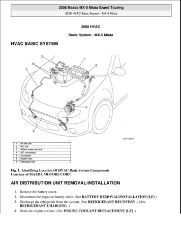
BASIC ELECTRICAL ENGINEERING FOR HVAC ENGINEERSA heating, ventilating and air-conditioning (HVAC) system is a simple system of heating andcooling exchangers using water or refrigerant (direct expansion system) as the medium. Pumpsmove the heated or cooled water to the exchangers. Fans then move the warmed or cooled aircreated at the exchangers to the occupied building interiors.So there are two stages to heating and cooling1. Water stage: water is the most efficient and inexpensive medium that we can cooldirectly (through a chiller) or heat (through a boiler)2. Air stage: air is the medium for heat exchange in the building as it can be cooled orheated through coils.The figure below illustrates a typical HVAC system showing water and air heat exchangers:Big energy users in HVAC1. Fans: for air circulation and ventilation.
2. Cooling: accomplished via chillers for the production of chilled water for large buildingsor for the use of direct expansion cooling systems such as packaged air-conditioners forsmall buildings.3. Heating: most frequently the energy use of boilers for the production of hot water forheating, but also often the use of electric heaters for zonal reheat.4. Pumps: for the circulation of heating hot water, chilled water and condenser water.5. Cooling towers: for heat rejection. The primary energy use is the cooling tower fan andpumps.Power distribution systems and equipment used to drive HVAC machinery, motors and otherauxiliaries can be complex to the non-electrical engineer. This course will address some basicelectrical concepts that will be useful to HVAC engineers and other mechanical engineers intheir day to day work. The course is divided in 4 sections:Part -1:Basic Electrical Concepts & FundamentalsPart -2:Electrical Distribution Systems and ComponentsPart -3:Motors and Variable Speed DrivesPart -4:Electrical Energy Efficiency in HVAC Systems
PART -1:BASIC ELECTRICAL FUNDAMENTALSIn each plant, the mechanical movement of different equipment is caused by an electric primemover (motor). Electrical power is derived from either utilities or internal generators and isdistributed through transformers to deliver usable voltage levels.Electricity is found in two common forms:1. AC (alternating current)2. DC (direct current)The selection of an energy source for equipment depends on its application, each having itsown merits and demerits, but for an HVAC system or typical building services, we areconcerned with AC voltage.Industrial AC voltage levels are roughly defined as LV (low voltage) and HV (high voltage) withfrequency of 50 to 60 Hz. An electrical circuit has the following three basic componentsirrespective of its electrical energy form:1. Voltage (V) is defined as the electrical potential difference that causes electrons to flow.2. Current (I) is defined as the flow of electrons and is measured in amperes.3. Resistance (R) is defined as the opposition to the flow of electrons and is measured inohms.All three are bound together with Ohm’s law, which gives the following relation between thethree:V I RIn a more technical expression, you can state it as:With Constant Resistance Lower voltage gives small current.
Higher voltage gives large current.With Constant Voltage Lower resistance passes large current. Higher resistance passes small current.Example: A conductor has a resistance of 1.5 ohms and the current flowing on the wire is 5amperes. The voltage drop along the wire will be the current times the resistance of theconductor or 7.5 volts.Example: A resistance type heating element from an electric water heater operating at 240volts has a current flow of 14.6 amperes. The resistance of the heating element will be thevoltage divided by the current or 16.4 ohms.CIRCUITSIn order to flow, electricity must have a continuous, closed path from start to finish; like a circle.The word “circuit” refers to the entire course an electric current travels, from the source ofpower, through an electrical device, and back to the source. Every circuit is comprised of threemajor components:1. A conductive "path," such as a wire, or printed etches on a circuit board;2. A "source" of electrical power, such as a battery or household wall outlet; and3. A "load" that needs electrical power to operate, such as a lamp.The current flows to the devices (called loads) through a “hot” wire and returns via a “neutral”wire because under normal conditions it’s maintained at zero volts, or what is referred to asground potential.There are also two optional components that can be included in an electrical circuit. These arecontrol devices and protective devices. Control and protective devices, however, are notrequired for a circuit to function. They are optional. For example, a circuit that switches on an airconditioner when the temperature is too high would contain the following components: a source of electrical energy, in this case, simple household current; a protective device that senses current flow on the circuit, the circuit breaker in the panelbox; a control device that redirects the current, the switch in the thermostat; and
a load such as an air conditioner that cools the space down until the circuit opens shuttingthe air conditioner off.Types of Circuits:There are several types of circuits. Their names describe the way the circuit is wired, or its mainfunction. Elementary types of circuits include: Series Parallel Open Short Power ControlSeries Circuit:A series circuit is defined as a circuit in which the elements in a series carry the same current,while voltage drop across each may be different. It has only one path for current to flow throughthe circuit. A typical series circuit is shown below:
Here are the basic rules of a series circuit. Current: In a series circuit the current (I) in amperes is the same everywhere in thecircuit.IT I1 I2 I3 Voltage: The total voltage of the circuit will be the sum of the voltages across each of theresistors in the circuit.VT V1 V2 V3 Resistance: The total resistance of the circuit will be the sum of the individual resistors inthe circuit.RT R1 R2 R3Parallel Circuit:A parallel circuit is defined as a circuit in which the elements in parallel have the same voltage,but the currents may be different. It has multiple paths for the current to follow as shown in thefigure below:
Basic Rules Voltage: The voltage will be the same across all resistors in the circuit and it will beequal to the supply voltage.VT V1 V2 V3 Current: The total current (I) in amperes flowing in the circuit will be the sum of thecurrents through each parallel branch of the circuit.IT I1 I2 I3 Resistance: The total resistance of a circuit where all resistors are in parallel is a littledifficult to determine. The reciprocal of the total resistance is the sum of the reciprocalsof each resistance. It is very important to note that the total resistance will be smallerthan the smallest resistance in the circuit. If all the resistors are of the same value, thenjust divide the resistance by the total number of resistors. A good way to solve for thetotal resistance is to assign a voltage to the circuit and then determine the total currentflow. Then divide the voltage by the total current flow using Ohm’s law to get the totalresistance.Open Circuits:An open circuit is a circuit where the path has been interrupted or "opened" at some point sothat current will not flow. An open circuit is also called an incomplete circuit.An open circuit could be intentional or un-intentional. An intentionally open circuit would be thecircuit to the lights in the room that are turned off. There is no closed path available for theelectricity to flow to the lights because the switch is in the "off" position which "opens" the paththe electricity would normally flow through.
An example of a circuit that is un-intentionally open is when a circuit breaker operates due to toomuch current on the circuit and shuts the circuit off. The common electrical industry terminologywould be to say that the circuit breaker or fuse "opened" or tripped the circuit. It did this by"opening" the switch in the circuit breaker.Short Circuits:A short circuit is a circuit in which the electricity has found an alternative path to return to thesource without going through an appropriate load. You can demonstrate this easily by taking afine piece of wire and connecting it to both the positive and negative terminals of a small battery.The wire will heat instantly and probably melt. In most circuits, this high amperage represents adangerous situation that could cause a fire or electrocute someone.Power Circuits:A power circuit is defined as any circuit that carries power to electrical loads. Power circuitsoften carry high voltages and consist of incoming main power, a motor starter, and the motor.This may seem like a simplistic definition but it is important to distinguish power circuits fromcontrol circuits since they serve different purposes.Control Circuits:A control circuit is a special type of circuit that uses control devices to determine when loads areenergized or de-energized by controlling current flow. Control circuits usually carry lowervoltages than power circuits.Consider a 600 hp large industrial motor driving a water pump. The motor is connected to a highvoltage electrical supply of 680V. When this motor is energized, it must draw enough current toget the water moving and it is common for a motor to draw about six times its normal operatingcurrent for a short period of time. This can be troublesome. The first concern is the operator's ability to safely close the switch.
The second concern is that when the operator opens the switch to turn the motor off, theelectricity will continue to try to complete the path. This will tend to arc between thecontacts of the switch as it is opened. This arcing is not only dangerous but alsodamages the switch by severely burning the contact points.A control circuit is used to ensure that the motor is started and stopped in a safe manner forboth the operator and the equipment.A common control circuit example is the thermostat to the air conditioner. The thermostat is partof a low-voltage control circuit that controls a relay that actually energizes and de-energizes thepower circuit to the air conditioning compressor.POWER (P)In DC circuits, power (watts) is simply a product of voltage and current.P Volts x AmpsFor AC circuits, the formula holds true for purely resistive circuits; however, for the followingtypes of AC circuits, power is not just a product of voltage and current. Single-phase power:Power (kW) Volts Amps power factor 3-phase power:Power (kW) 1.73 Volts Amps power factorPower consumption:The total amount of energy used is estimated by multiplying the power by the length of time theload is on. This is most commonly expressed in "Kilowatt Hours" (or kWh) and is what the powercompany generally uses to calculate your bill. A kilowatt-hour (kWh) is 1,000 watts used for onehour. As an example, a 100-watt light bulb operating for ten hours would use one kilowatt-hour.Power factor:Power factor is defined as the ratio of real power to apparent power. The maximum value it cancarry is either 1 or 100(%), which would be obtained in a purely resistive circuit.Power factor True power / Apparent power
Apparent power (VA) is the product of voltage and ampere, i.e., VA or kVA is known asapparent power. Apparent power is total power supplied to a circuit inclusive of the trueand reactive power. Real power or true power is the power that can be converted into work and ismeasured in watts. Reactive power: If the circuit is of an inductive or capacitive type, then the reactivecomponent consumes power and cannot be converted into work. This is known asreactive power and is denoted by the unit VAR.Relationship between powers: Apparent power (VA) V A True power (Watts) VA cosφ Reactive power (VAR) VA sinφPower factor of a circuit is a number that can range from zero to one and it only occurs in analternating current circuit. Inductance or capacitance in a circuit can cause the voltage sinewave and the current sine wave not to be lined up so they do not reach a peak or zero at exactlythe same time. When that happens, the power factor drops below one. The more out ofalignment the current and voltage become, the lower will be the power factor of the circuit.Electric motors have high inductance and, therefore, they generally have a power factor that isless than 1.0. For an incandescent light bulb or a resistance type electric heater the voltage andcurrent will be in alignment and the power factor will be 1.0. That is why the current drawn by alight bulb can be simply determined by dividing the wattage by the voltage.In the case of a 3-phase circuit, there are three conductors supplying the load rather than onlytwo wires as in the case of a single-phase load. The current in one conductor supplying the 3phase load is 120E shifted in phase from the current flowing in each of the other wires. A factorthat takes all of this into account is the number 1.73 which is the square root of three. You cansee by comparing the previous two formulas that if the power, voltage, and power factor are thesame, less current will be flowing to a three-phase load as to a single-phase load of the samewattage.
POWER SUPPLYSingle Phase Power:Single Phase power refers to two wire power circuits with one power conductor and one neutralconductor. Most residential homes are fed with single-phase power. The power company runsthree wires into a home, which comprises of two hot wires and a neutral wire. The neutral isactually a center-tapped feed off the transformer. Voltage measured across both hot wires is240 VAC and the voltage measured from any hot to neutral is 120 VAC (split-phase). Somepeople mistakenly believe that a 240 VAC circuit is "two-phase", but it's actually the full phase ofa single-phase circuit whereas the 120 VAC feeds are half-phase (split-phase).Single Phase Three WireThe selling feature of 240-volt power is that it’s twice as powerful and twice as efficient as 120volts (allows you to run higher–wattage appliances at half the amperes). Line 1 to neutral and Line 2 to neutral are used to power 120 volt lighting and plug loads. Line 1 to Line 2 is used to power 240 volt single phase loads such as a water heater,electric range, or air conditioner.3 - Phase Power:Three Phase power has three power conductors (120V, 120V, 120V) out of phase with oneanother and one neutral conductor. For our purposes let’s consider a 3 Phase 4 Wire208Y/120V power circuit. This arrangement provides (3) 120V single phase power circuitsand/or (1) 208V three phase power circuit.
Three Phase Four Wire WyeThe most common commercial building electric service in North America is 120/208 volt wye,which is used to power 120 volt plug loads, lighting, and smaller HVAC systems.In larger facilities the voltage is 277/480 volt and used to power larger HVAC loads.Three Phase Four Wire Wye
Three Phase Three Wire Delta:Used primarily in industrial facilities, 3-wire delta configuration is used to provide power forthree-phase motor loads, and in utility power distribution applications. Nominal service voltagesof 240, 400, 480, 600, and higher are typical.Three Phase Three Wire DeltaCONDUCTORSThe general term “conductor” applies to anything that permits, or conducts, the flow ofelectricity. Electricity flows in the path of least resistance, and certain materials allow energy toflow more freely than others. Copper, for example, is a good conductor, although aluminum andcopper-clad aluminum wires are also used. Insulators are materials that hold back the flow ofelectric current. Wood and plastic are good insulators.Electric wires:Electrical wires are conductors that are sized in two different systems: the American WireGauge System (AWG) and the Thousand Circular Mill system (KCMIL), which was known untilrecently as (MCM). Both systems designate wire size based on their diameters or crosssectional areas. The American Wire Gauge system is used to refer to relatively small wires.AWG sizes: 16gauge to 0000 (4/0). Size increases as the number decreases. 16 gauge smallest .05” 4/0 largest .46” 14 gauge copper wire is the minimum gauge allowed in construction. MCM: cable larger than 4/0. Sizes are 250, 300, 400, 500 (measurement representingsquare of cable diameter in thousandths of an inch).
Ampacity:The current carrying capacity of a particular wire is dictated by its "ampacity" - how many ampsit can handle. Ampacity is a function of the cross section area or diameter of the wire and itsmaterial type. Larger diameter wires have larger cross section areas and can safely carry moreelectrical current without overheating. The maximum ampacity for different types of wires isreported in the electrical codes and standards and tabulated based on the size of the wire,temperature application and the insulation type for the particular wire.Materials:Basic conductors: copper and aluminum Aluminum conductors must be larger to carry same amperage but are lighter and havelower installation cost. Furthermore, they require special installation because jointsloosen and oxides form, causing resistance and overheating. Copper conductors are cost effective in small and medium sized wires.Conductor Resistance:The resistance of a conductor depends upon the type of material. For example, copper is abetter conductor than aluminum; therefore, the resistance of an aluminum wire is higher thanthe resistance of a copper wire of the same size and length.Wire resistance increases as the temperature increases, and decreases as the temperaturedecreases. As a rough approximation, the resistance of a wire will change about 8% for every25ºC change in conductor temperature.The resistance of a wire is proportional to the length of the wire.The resistance of a wire decreases as the cross-sectional area of the wire increases. Forexample a size 10 AWG wire has about four times the cross-sectional area of a size 16 AWGwire.
PART - 2ELEMENTS OF POWER DISTRIBUTIONAs electrical energy is generated, it is transformed and transported instantaneously through anetwork of wires, substations, and transformers to the consumer. Electricity is generated at acomparatively low voltage 6.6 kV, 11 kV or 33 kV (r.m.s.) depending on the design of generatorand is stepped up via step up transformers to values as high as 69 kV to 132 kV or higherbefore it is fed into the transmission lines. The cables themselves are usually made of aluminum(low resistivity) on a steel core (strength) and are supported by means of strings of ceramicinsulators on steel pylons. This network of transmission lines and pylons forms the Grid System.To supply the power needs of a particular region this voltage will be stepped-down at a SubStation to the required voltage. This voltage may then be further reduced by smaller Sub-StationTransformers. A Tertiary Grid System (Voltage at this point is 11 kV) has many branchesfeeding small local Sub-Station Transformers where the voltage is finally reduced to 480/240Vlevels.From the generating station to the final destination, the energy from generated electricityundergoes numerous changes in voltage and direction. Each change requires expert designand handling to provide the consumer with the least expensive, most reliable energy they canbuy.Substation, Switchyard, Switchgear: Substation is place where high voltage is stepped down via step-down transformers.Most substations include one or more transformers and switchgear to control the flow ofelectricity into and out of the substation.When we define substation, we call it220/33kV, 100MVA substation. Substation can be indoor as well as outdoor. Switchyards deliver the generated power from power plant at desired voltage level to thenearest grid. When we define switchyard, we call it 220kV switchyard, 33kV switchyard.Switchyards are generally in open yards. A large fence is generally used to keep thepublic out of switchyards and open substations since high voltage electricity isdangerous. Switchgear is a combination of switching devices such as electrical disconnect fusesand/or circuit breakers, relays and other electrical controls used for control, metering(measurement) and switching. Switchgear is used both to de-energize equipment toallow work to be done and to clear faults downstream.
Power Distribution:For reasons of economy and efficiency, it is preferable to transmit electricity at High Voltage.The power generated: P V x I (Watts).However, certain losses occur during the conducting process which amount to: I2 x R (Watts).Power Available (V x I) - (I2 x R)(Watts)These losses must therefore be kept as small as possible.This means that either I or R must be kept small.To keep R, small metal with Low Resistivity (Copper or Aluminum) could be used in cables witha large diameter but a thick cable over long distances would be very expensive.It is preferable therefore to reduce “current, I”.This can be done, but to maintain the same power output the voltage must be increased. To dothis, a Transformer is used.Transformers:The transformer is the heart of the substation. The transformer changes the relationshipbetween the incoming voltage and current and the outgoing voltage and current. It consists oftwo separate coils of wire wound around a laminated steel core. When an alternating current ispassed through one coil of wire the current flow creates a magnetic field around the coil. Thesecond coil of wire, usually wound directly over the first coil, is within the magnetic field createdby the current in the first coil. Because the current in the first coil is alternating back and forth,the magnetic field will be in constant motion. The moving magnetic field induces a current flowin the second coil of wire. The relationship between the voltage of the first coil and the voltage ofthe second coil is directly proportional to the number of turns of wire on the first coil ascompared to the number of turns of wire on the second coil. If the first coil (called the primarywinding) has twice as many turns as the second coil (called the secondary winding), then thevoltage of the secondary winding will be only half that of the primary winding. This is also calledthe “Turns Ratio”.Cold rolled grain oriented (CRGO) steel is used as the core material to provide a low reluctance,low loss flux path. The steel is in the form of varnished laminations to reduce eddy current flowand losses on the account of this.
There is a very simple and straight relationship between the potential across the primary coiland the potential induced in the secondary coil. The ratio of the primary potential to thesecondary potential is the ratio of the number of turns in each and is represented as follows:N1/N2 V1/V2Where: N1 Number of turns in primary N2 Number of turns in secondary V1 Voltage in primary V2 Voltage in secondaryAnother important fundamental principle of transformers is that when the transformer is loaded,the current is inversely proportional to the voltages and is represented as follows:N1/N2 V1/V2 I2/I1 N1 Number of turns in primary N2 Number of turns in secondary V1 Voltage in primary V2 Voltage in secondary I1 Current in primary I2 Current in secondaryIn an actual transformer there are some losses due to heating and this does not hold exactlyturn. However, for the purpose of installing transformers and wiring as well as overcurrentprotection for transformers, this relationship is assumed to be turn because it represents a worst
case situation. It is important to note in the following formula that if the secondary voltage is onlyhalf the primary voltage, the secondary current will need to be double the primary current tokeep both sides of the equation equal.SECONDARY POWER DISTRIBUTIONElectric energy leaves the distribution substation and is distributed on three phase distributionlines to switchboards. The supply or intake cable may enter the building through anunderground duct or via an overhead supply. An underground supply is preferred since all of theelectrical service is hidden. The supply cable is terminated in the board’s fused sealing chamberwhich houses an electric meter to record the electricity consumed in units of kilowatt/hour alongwith peak demand.Switchboards take a large block of power and break it down into separate circuits, each of whichis controlled and protected by the fuses or switchgear of the switchboard.
Typical Secondary Power DistributionElectric Switchboard:An electric switchboard is a device that directs electricity from one source to another. The role ofa switchboard is to divide the main current provided to the switchboard into smaller currents forfurther distribution and to provide switching, current protection and metering for these variouscurrents. In general, switchboards distribute power to transformers, panelboards, controlequipment, and ultimately to system loads, MCC.Inside the switchboard there is a bank of busbars (flat strips of copper or aluminum) to which theswitchgear is connected. These carry large currents through the switchboard, and are supportedby insulators. A switchboard may include a metering or control compartment separated from thepower distribution conductors.Panelboard:A panelboard is an enclosed assembly with circuit breakers, or fused switches, or rarely, fusesassembled to a bus. Branch circuits feed power to receptacles, switches, fixtures andappliances in different areas of the building.
A 120 volt circuit consists of one hot conductor and one neutral conductor. The hotconductor originates at the breaker or fuse connected to one of the hot bus bars. A 240 volt circuit requires both hot bus conductors, so it originates at a breaker or fuseconnected to both hot bus bars.While panelboards and switchboards both perform power control and circuit protectionfunctions, there are key differences between these systems. A panelboard must be mounted inor against a wall; whereas, some switchboards must be installed away from a wall to allowaccess to the rear of the unit for installation and maintenance purposes. Perhaps the keydifference; however, is the amount of power controlled by each type of system. In general,switchboards can be configured to include larger circuit breakers or switches so that they canhandle greater amounts of current. This also means that switchboards may be more complexand can incorporate a broader range of devices.Motor Control Center (MCC):A motor control center is a factory assembled grouping of one or more vertical metal cabinetsections with power bus and other switchgear for controlling a group of motor feeders. Eachsection may contain compartmentalized starters, feeders, transformers, adjustable frequencydrives and panelboards just to mention a few. Depending upon the size, most starters andfeeders may be plug in type. These units are typically rated up to 600 volts AC.They are modular in design, compartmentalized, fixed or draw-out type suitable for indoor oroutdoor installations. Motor control centers provide wire ways for field control and power cablesand can be specified with a range of options such as separate control transformers, pilot lamps,control switches, extra control terminal blocks, various types of bi-metal and solid-state overloadprotection relays, or various classes of power fuses or types of circuit breakers.
A Typical Motor Control CenterA motor control center can either be supplied ready for the customer to connect all field wiring,or can be an engineered assembly with internal control and interlocking wiring to a centralcontrol terminal panel board or programmable controller. The enclosure of MCC is classifiedaccording to its capability of withstanding the entry of solid particles such as dust and vermin aswell as liquids such as water, oil, etc.NEMA rated motor control centers are usually the standard in the USA, Canada and most ofMexico. IEC rated motor control centers are usually found in Europe, Asia, Australia and Brazil.The standards provide the description of enclosure rating, busbar, short circuit & seismic rating,and wire class drawings.Control Panel:A control panel consists of a controller. Controller may be PLC, DCS, relay or some other type.It gives digital signal input signal to the MCC panel to start the motor. Control panel worksbased on the PLC /DCS program or the relay logic. Instruments are normally connected tocontrol panel. Indications for the interlocks also will be in the control panel. Today single panelsare more common by using separate control and MCC panels.Busbars:Busbars are conductors that serve as a common connection for two or more circuits. Thesecondary of the transformer is typically suspended from the ground on insulators connected toa rigid metallic bar, which is then tapped at several points to supply power for the distributionfeeders. Engineers refer to such an energized bar as "busbar" or simply "bus." A busbar is usedin place of a wire due to its rigidity and larger current carrying capacity. The material used for
busbars is E91 E grade aluminum or electrolytic grade copper. The precautions that are to betaken while selecting and mounting busbars are: Busbars are sized considering system fault current and for specified load current withrespect to ambient temperature and final working temperature. Busbars should be insulated and properly supported with adequate clearances betweenphases-neutral-earth. For MCC, the main bus should be rated to carry 125% of the largest motor ru
BASIC ELECTRICAL ENGINEERING FOR HVAC ENGINEERS A heating, ventilating and air-conditioning (HVAC) system is a simple system of heating and cooling exchangers using water or refrigerant (direct expansion system) as the medium. Pumps move the heated or cooled water t