Transcription
TeAMYYePGDigitally signed byTeAM YYePGDN: cn TeAM YYePG,c US, o TeAM YYePG,ou TeAM YYePG,email yyepg@msn.comReason: I attest to theaccuracy and integrityof this documentDate: 2005.05.2606:18:45 08'00'
PrefacePractical Troubleshooting of Electrical Equipmentand Control Circuitsi
iiContentsOther titles in the seriesPractical Cleanrooms: Technologies and Facilities (David Conway)Practical Data Acquisition for Instrumentation and Control Systems (John Park, Steve Mackay)Practical Data Communications for Instrumentation and Control (Steve Mackay, Edwin Wright,John Park)Practical Digital Signal Processing for Engineers and Technicians (Edmund Lai)Practical Electrical Network Automation and Communication Systems (Cobus Strauss)Practical Embedded Controllers (John Park)Practical Fiber Optics (David Bailey, Edwin Wright)Practical Industrial Data Networks: Design, Installation and Troubleshooting (Steve Mackay,Edwin Wright, John Park, Deon Reynders)Practical Industrial Safety, Risk Assessment and Shutdown Systems for Instrumentation and Control(Dave Macdonald)Practical Modern SCADA Protocols: DNP3, 60870.5 and Related Systems (Gordon Clarke, DeonReynders)Practical Radio Engineering and Telemetry for Industry (David Bailey)Practical SCADA for Industry (David Bailey, Edwin Wright)Practical TCP/IP and Ethernet Networking (Deon Reynders, Edwin Wright)Practical Variable Speed Drives and Power Electronics (Malcolm Barnes)Practical Centrifugal Pumps (Paresh Girdhar and Octo Moniz)Practical Electrical Equipment and Installations in Hazardous Areas (Geoffrey Bottrill andG. Vijayaraghavan)Practical E-Manufacturing and Supply Chain Management (Gerhard Greef and Ranjan Ghoshal)Practical Grounding, Bonding, Shielding and Surge Protection (G. Vijayaraghavan, Mark Brown andMalcolm Barnes)Practical Hazops, Trips and Alarms (David Macdonald)Practical Industrial Data Communications: Best Practice Techniques (Deon Reynders, Steve Mackayand Edwin Wright)Practical Machinery Safety (David Macdonald)Practical Machinery Vibration Analysis and Predictive Maintenance (Cornelius Scheffer andParesh Girdhar)Practical Power Distribution for Industry (Jan de Kock and Cobus Strauss)Practical Process Control for Engineers and Technicians (Wolfgang Altmann)Practical Power Systems Protection (Les Hewitson, Mark Brown and Ben. Ramesh)Practical Telecommunications and Wireless Communications (Edwin Wright and Deon Reynders)Practical Hydraulics (Ravi Doddannavar, Andries Barnard)Practical Batch Process Management (Mike Barker, Jawahar Rawtani)
PrefacePractical Troubleshooting of ElectricalEquipment and Control CircuitsMark Brown Pr.Eng, DipEE, B.Sc (Elec Eng),Senior Staff Engineer, IDC Technologies, Perth, AustraliaJawahar Rawtani M.Sc (Tech), MBA,Senior Electrical Engineer, Nashik, IndiaDinesh Patil BEng,Patil and Associates.Series editor: Steve Mackay FIE (Aust), CPEng, B.Sc (Elec.Eng), B.Sc (Hons), MBA,Gov.Cert.Comp., Technical Director – IDC TechnologiesAMSTERDAM BOSTON HEIDELBERG LONDONNEW YORK OXFORD PARIS SAN DIEGOSAN FRANCISCO SINGAPORE SYDNEY TOKYONewnes is an imprint of Elsevieriii
iv ContentsNewnesAn imprint of ElsevierLinacre House, Jordan Hill, Oxford OX2 8DP30 Corporate Drive, Burlington, MA 01803First published 2005Copyright 2005, IDC Technologies. All rights reservedNo part of this publication may be reproduced in any material form (includingphotocopying or storing in any medium by electronic means and whetheror not transiently or incidentally to some other use of this publication) withoutthe written permission of the copyright holder except in accordance with theprovisions of the Copyright, Designs and Patents Act 1988 or under the terms ofa licence issued by the Copyright Licensing Agency Ltd, 90 Tottenham Court Road,London, England W1T 4LP. Applications for the copyright holder’s writtenpermission to reproduce any part of this publication should be addressedto the publisherBritish Library Cataloguing in Publication DataBrown, MarkPractical troubleshooting electrical equipment1. Electrical fault location 2. Electric machinery – maintenance and repair3. Electric engineering – materials – testingI. Title II. Rawtani, Jawahar III. Patil,Dinesh621.3'192Library of Congress Cataloguing in Publication DataA catalogue record for this book is available from the Library of CongressISBN0 7506 6278 6For information on all Newnes Publicationsvisit our website at www.newnespress.comTypeset and edited by Integra Software Services Pvt. Ltd, Pondicherry, Indiawww.integra-india.comPrinted and bound in The NetherlandsWorking together to growlibraries in developing countrieswww.elsevier.com www.bookaid.org www.sabre.org
PrefacevContentsPreface. vii1Basic principles . 11.1Introduction . 11.2Basic principles of electrical machines . 121.3AC power systems . 191.4Meters used in troubleshooting. 222Devices, symbols, and circuits. 242.1Devices and symbols. 242.2Electrical circuits. 242.3Reading and understanding electrical drawings. 282.4Reading and understanding ladder logic . 362.5Wires and terminal numbering. 393Basic troubleshooting principles . 423.1Introduction . 423.2Basic principles in using a drawing and meter in troubleshooting circuits . 433.3Checks for circuit continuity with disconnected supply. 443.4Checks for circuit continuity with live supply . 473.5Tests and methods. 483.6Testing devices . 493.7Circuits . 613.8Accurate wiring of circuits and connections . 623.9Tests for installation and troubleshooting. 664Troubleshooting AC motors and starters . 684.1Introduction . 684.2Fundamentals of three-phase AC motors . 684.3Fundamental of single-phase AC motors. 784.4DC motors . 814.5Motor enclosures. 854.6Motor terminal identification and connection diagram . 864.7Motor rating and insulation types. 884.8Operating a motor for forward and reverse operation . 904.9Motor braking methods. 914.10Motor testingt .1004.11Measurements used for a motor.1064.12Motor failures and methods to extend its life.106
viContents4.134.14Motor control trouble–remedy table . 107Motor starter check chart . 1095Switches, circuit breakers and switchboards. 1125.1Introduction. 1125.2Switches and circuit breakers . 1125.3Overloads and fault protection . 1185.4Switchboards . 1195.5Motor control center. 1206Troubleshooting variable speed drives. 1216.1The need for VSDs . 1216.2Basic VSD . 1216.3Power electronic components. 1236.4Electrical VSDs. 1326.5Power electronic rectifiers (AC/DC converters) . 1356.6Gate-commutated inverters (DC/AC converters) . 1496.7Overall protection and diagnostics . 1576.8Installations and commissioning . 1606.9Power supply connections and earthing requirements . 1636.10Precautions for start/stop control of AC drives . 1666.11Control wiring for VSDS. 1696.12Commissioning VSDs . 1707Troubleshooting control circuits . 1737.1Basic control circuits . 1737.2Ladder logic circuits . 1777.3Two-wire control . 1787.4Three-wire control – start/stop . 1797.5Jog/inch circuits . 1807.6Sequence start and stop. 1817.7Automatic sequence starting. 1837.8Reversing circuit . 1837.9Plug stop and anti-plug circuits . 1877.10Two-speed motor control . 1897.11Overload protection . 1897.12Troubleshooting examples. 1907.13Troubleshooting strategies. 1927.14Ladder logic design exercise . 194Appendix A: Units and abbreviations . 195Appendix B: Troubleshooting. 196Appendix C: Low-voltage networks. 213Index . 232
PrefaceviiPrefaceThere is a large gap between the theory of electron flow, magnetic fields and that of troubleshootingelectrical equipment and control circuits in the plant. In this book, we try to avoid or at least minimizediscussions on the theory and instead focus on showing you how to troubleshoot electrical equipmentand control circuits. The book helps to increase your knowledge and skills in improving equipmentproductivity whilst reducing maintenance costs. Reading this book will help you identify, prevent andfix common electrical equipment and control circuits. The focus is ‘outside the box’. The emphasis ison practical issues that go beyond typical electrical theory and focus on providing those that attendwith the necessary toolbox of skills in solving electrical problems, ranging from control circuits tomotors and variable speed drives.This book focuses on the main issues of troubleshooting electrical equipment and control circuits oftoday to enable you to walk onto your plant or facility to troubleshoot and fix problems as quickly aspossible. This is not an advanced book but one aimed at the fundamentals of troubleshooting systems.The book is very practical in its approach to troubleshooting and the examples you will be shown areapplicable to any facility.We would hope that you will gain the following knowledge from this book: Diagnose electrical problems ‘right-first-time’Minimize the expensive trial and error troubleshooting approachReduce unexpected downtime on electrical motors and other equipmentImprove plant safetyLearn specific techniques to troubleshoot equipment and control circuitsAnalyze equipment problemsDetermine causes of equipment failureTroubleshoot electrical equipment and control circuits.Typical people who will find this book useful include: Plant ElectriciansMechanical EngineersProduction Operators and SupervisorsUtilities Maintenance PersonnelPlant Engineers.Pre-requisitesA basic understanding of electrical theory and problems you have encountered in the past would behelpful but a basic review is undertaken at the beginning of the book.
1Basic principlesObjectives 1.1To refresh basic electrical conceptsTo define basic concepts of transformerTo refresh single-phase power conceptsTo refresh three-phase power concepts.IntroductionA significant proportion of industrial electricity is about single-phase and three-phasetransformers, AC and DC machines. In this context, we will study the electrical circuitsand their construction, design, testing, operation, and maintenance.For troubleshooting electrical equipment and control circuits, it is important tounderstand the basic principles on which the electrical equipment works. The followingsections will outline the basic electrical concepts.1.1.1Basic electrical conceptsIn each plant, the mechanical movement of different equipments is caused by an electricprime mover (motor). Electrical power is derived from either utilities or internalgenerators and is distributed through transformers to deliver usable voltage levels.Electricity is found in two common forms: AC (alternating current) DC (direct current).Electrical equipments can run on either of the AC/DC forms of electrical energies. Theselection of energy source for equipment depends on its application requirements. Eachenergy source has its own merits and demerits.Industrial AC voltage levels are roughly defined as LV (low voltage) and HV (highvoltage) with frequency of 50–60 Hz.An electrical circuit has the following three basic components irrespective of itselectrical energy form: Voltage (volts) Ampere (amps) Resistance (ohms).
2Practical Troubleshooting of Electrical Equipment and Control CircuitsVoltage is defined as the electrical potential difference that causes electrons to flow.Current is defined as the flow of electrons and is measured in amperes.Resistance is defined as the opposition to the flow of electrons and is measured inohms.All three are bound together with Ohm’s law, which gives the following relationbetween the three:V I RWhereV VoltageI CurrentR Resistance.(a) PowerIn DC circuits, power (watts) is simply a product of voltage and current.P V IFor AC circuits, the formula holds true for purely resistive circuits; however, for thefollowing types of AC circuits, power is not just a product of voltage and current.Apparent power is the product of voltage and ampere, i.e., VA or kVA is known asapparent power. Apparent power is total power supplied to a circuit inclusive of the trueand reactive power.Real power or true power is the power that can be converted into work and is measuredin watts.Reactive power If the circuit is of an inductive or capacitive type, then the reactivecomponent consumes power and cannot be converted into work. This is known asreactive power and is denoted by the unit VAR.(b) Relationship between powersApparent power (VA) V ATrue power (Watts) VA cos φReactive power (VAR) VA sin φ(c) Power factorPower factor is defined as the ratio of real power to apparent power. The maximumvalue it can carry is either 1 or 100(%), which would be obtained in a purely resistivecircuit.Power factor True powerApparent powerWattskVA(d) Percentage voltage regulation% Regulation 100(No load voltage Full load voltage)Full load voltage
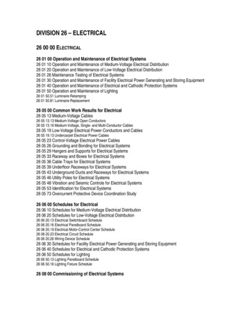
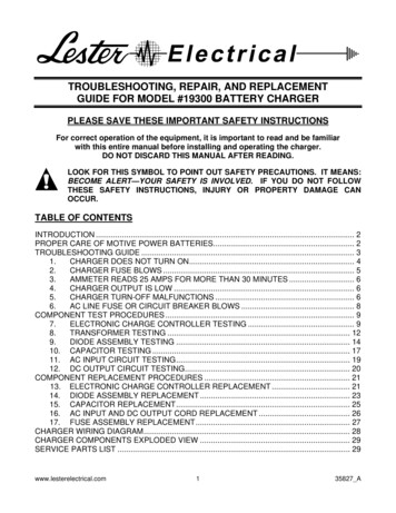
Basic principles3(e) Electrical energyThis is calculated as the amount of electrical energy used in an hour and is expressed asfollows:Kilowatthour kW hWherekW kilowatth hour.(f) Types of circuitsThere are only two types of electrical circuits – series and parallel.A series circuit is defined as a circuit in which the elements in a series carry the samecurrent, while voltage drop across each may be different.A parallel circuit is defined as a circuit in which the elements in parallel have the samevoltage, but the currents may be different.1.1.2TransformerA transformer is a device that transforms voltage from one level to another. They arewidely used in power systems. With the help of transformers, it is possible to transmitpower at an economical transmission voltage and to utilize power at an economiceffective voltage.Basic principleTransformer working is based on mutual emf induction between two coils, which aremagnetically coupled.When an AC voltage is applied to one of the windings (called as the primary), itproduces alternating magnetic flux in the core made of magnetic material (usually someform of steel). The flux is produced by a small magnetizing current which flowsthrough the winding. The alternating magnetic flux induces an electromotive force(EMF) in the secondary winding magnetically linked with the same core and appears asa voltage across the terminals of this winding. Cold rolled grain oriented (CRGO) steelis used as the core material to provide a low reluctance, low loss flux path. The steel isin the form of varnished laminations to reduce eddy current flow and losses on accountof this.Typically, the coil connected to the source is known as the primary coil and the coilapplied to the load is the secondary coil.A schematic diagram of a single-phase transformer is shown in the Figure 1.1.A single-phase transformer consists mainly of a magnetic core on which twowindings, primary and secondary, are wound. The primary winding is supplied withan AC source of supply voltage V1. The current I flowing in the primary windingproduces flux, which varies with time. This flux links with both the windings andproduces induced emfs. The emf produced in the primary winding is equal andopposite of the applied voltage (neglecting losses). The emf is also induced in thesecondary winding due to this mutual flux. The magnitude of the induced emfdepends on the ratio of the number of turns in the primary and the secondarywindings of the transformer.
4Practical Troubleshooting of Electrical Equipment and Control CircuitsφIφ – N2N1V1–E1––E2PS V2 Z Figure 1.1Schematic diagram of a single-phase transformerPotential-inducedThere is a very simple and straight relationship between the potential across the primarycoil and the potential induced in the secondary coil.The ratio of the primary potential to the secondary potential is the ratio of the numberof turns in each and is represented as follows:N1 V1 N 2 V2The concepts of step-up and step-down transformers function on similar relation.A step-up transformer increases the output voltage by taking N 2 N1 and a step-downtransformer decreases the output voltage by taking N 2 N1.Current-inducedWhen the transformer is loaded, then the current is inversely proportional to the voltagesand is represented as follows:V1 I 2 N1 V2 I1 N 2EMF equation of a transformer:rms value of the induced emf in the primary winding is:E1 4.44 f N1 φmrms value of the induced emf in the secondary winding is:E2 4.44 f N 2 φmWhereN1 Number of turns in primaryN2 Number of turns in secondaryφ m Maximum flux in core andf Frequency of AC input in Hz.
Basic principles1.1.35Ideal transformerThe following assumptions are made in the case of an ideal transformer: No loss or gain of energy takes place. Winding has no ohm resistances. The flux produced is confined to the core of the transformer, which links fullyboth the windings, i.e., there is no flux leakage. Hence, there are no I 2R losses and core losses. The permeability of the core is high so that the magnetizing current required toproduce the flux and to establish it in the core is negligible. Eddy current and hysteresis losses are negligible.1.1.4Types of transformers1. As per the type of construction(a) Core type:(b) Shell type:Windings surround a considerable part of the core.Core surrounds a considerable portion of the windings.2. As per cooling type(a) Oil-filled self-cooled: Small- and medium-sized distribution transformers.(b) Oil-filled water-cooled: High-voltage transmission line outdoor transformers.(c) Air Cooled type: Used for low ratings and can be either of natural aircirculation (AN) or forced circulation (AF) type.3. As per application(a) Power transformer : These are large transformers used to change voltagelevels and current levels as per requirement. Power transformers are usuallyused in either a distribution or a transmission line.(b) Potential transformer (PT): These are precision voltage step-down transformers used along with low-range voltmeters to measure high voltages.(c) Current transformer (CT): These transformers are used for the measurementof current where the current-carrying conductor is treated as a primarytransformer. This transformer isolates the instrument from high-voltage line, aswell as steps down the current in a known ratio.(d) Isolation transformer : These are used to isolate two different circuitswithout changing the voltage level or current level.A few important points about transformers: Used to transfer energy from one AC circuit to anotherFrequency remains the same in both the circuitsNo ideal transformer existsAlso used in metering applications (current transformer, i.e., CT, potentialtransformers, i.e., PT) Used for isolation of two different circuits (isolation transformers) Transformer power is expressed in VA (volt amperes) Transformer polarity is indicated by using dots. If primary and secondarywindings have dots at the top and bottom positions or vice versa in diagram,then it means that the phases are in inverse relationship.
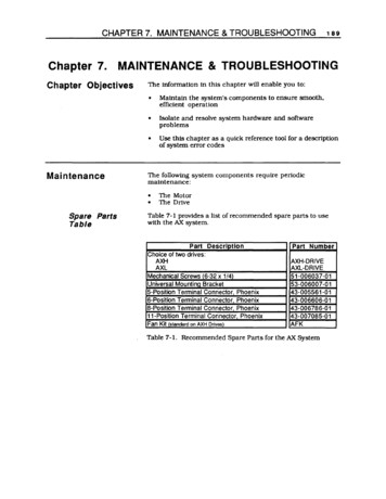
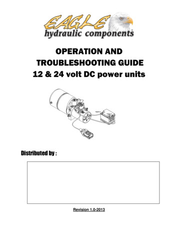
6Practical Troubleshooting of Electrical Equipment and Control Circuits1.1.5Connections of single-phase transformerDepending on the application’s requirement, two or more transformers have to beconnected in a series or parallel circuits. Such connections can be undertaken as depictedin the following diagram examples:(a) Series connection of two single-phase transformersAs shown in Figure 1.2, two transformers can be connected in a series connection. If bothare connected as in Figure 1.2 then voltage twice that of voltage rating of the individualtransformer can be applied. Their current rating must be equal and high enough to carryload current. Precaution should be taken to connect transformers windings, keeping inmind the polarity. In the above example, primary total turns to secondary total turns are inthe 2:1 ratio, leading to half voltage.H1480 V AC(200 turns)Xmer 1H2H3(100 turns)(200 turns)Xmer 2(400 turns)Pri. sideSec. side(200 turns)(100 turns)X3X4H4X2240 V ACX1Figure 1.2Series connection of two single-phase transformers(b) Parallel connection of two single-phase transformersAs shown in Figure 1.3, two transformers are connected in series on the primary sidewhile the secondary sides are connected in parallel.H1480 V AC(200 turns)XmerH2H4H3(200 turns)Xmer 2(400 turns)Pri. sideSec. side(100 turns)X3X2X1X4120 V ACFigure 1.3Parallel connection of two single-phase Transformers
Basic principles7On the primary side, the number of turns is added while on the secondary side theyremain as it is due to their parallel condition.LVDT (linear voltage differential transformer) is the best practical example of the basictransformer and its series connection. Use of transformers with such connections can poseproblems of safety and load sharing and are hardly used in practical power circuits. It ispossible to deploy these connections while designing control transformers if such use willhave any specific advantage. Parallel operation of two separate transformers is possibleunder specific conditions to meet an increased load requirement but the risks involvedmust be properly evaluated.1.1.6Three-phase transformersLarge-scale generation of electric power is generally three-phasic with voltages in 11 or32 kV. Such high three-phasic voltage transmission and distribution requires use of thethree-phase step-up and step-down transformers.Previously, it was common practice to use three single-phase transformers in place of asingle three-phase transformer. However, the consequent evolution of the three-phasetransformer proved space saving and economical as well.Still, construction-wise a three-phase transformer is a combination of three single-phasetransformers with three primary and three secondary windings mounted on a core havingthree legs.Commonly used three-phases are: Three-phase three-wire (delta) Three-phase four-wire (star).1. Delta connectionIt consists of three-phase windings (Figure 1.4) connected end-to-end and are 120 apart fromeach other electrically. Generally, the delta three-wire system is used for an unbalanced loadsystem. The three-phase voltages remain constant regardless of load imbalance.VL VphWhereVL line voltageVph phase voltage.Relationship between line and phase currents:I L 3 I phWhereI L line currentI ph phase current.2. Three-phase four-wire star connectionsThe star type of construction (Figure 1.5) allows a minimum number of turns per phase(since phase voltage is 1/ 3 of line voltage) but the cross section of the conductor willhave to be increased as the current is higher compared to a delta winding by a factor of3 . Each winding at one end is connected to a common end, like a neutral point –therefore, as a whole there are four wires.
8Practical Troubleshooting of Electrical Equipment and Control CircuitsBBRYYYPri. sideSec. sideRBRFigure 1.4Three-phase transformer delta connection on primary sideA three-wire source as obtained from a delta winding may cause problems when feedingto a star connected unbalanced load. Because of the unbalance, the load neutral will shiftand cause change of voltage in the individual phases of the load. It is better to use a starconnected four-wire source in such cases. Three-wire sources are best suited for balancedloads such as motors.BBYRBYPri. sideRNFigure 1.5Three-phase four-wire transformer star connectionYNSec. sideRN
Basic principles9Relationship between line and phase voltages:VL 3 VphWhereVL line voltageVph phase voltage.Relationship between line and phase currents:I L I phWhereI L line currentI ph phase current.Output power of a transformer in kW:P 3 VL I L cos φ [ kW ]WhereVL line voltageI L line currentcos φ power factor.3. Possible combinations of star and deltaThe primary and secondary windings of three single-phase transformers or a three-phasetransformer can be connected in the following ways: Primary in delta – secondary in deltaPrimary in delta – secondary in starPrimary in star – secondary in starPrimary in star – secondary in delta.Figure 1.6 shows the various types of connections of three-phase transformers. On theprimary side, V is the line voltage and I the line current. The secondary sideline voltagesand currents are determined by considering the ratio of the number of turns per phase(a N1/N2) and the type of connection. Table 1.1 gives a quick view of primary-linevoltages and line currents and secondary-phase voltages and currents. The powerdelivered by the transformer in an ideal condition irrespective of the type of connection 1.732 VL, IL assuming cosφ 1.1.1.7Testing transformersThe following tests are carried out on transformers: Measurement of winding resistanceMeasurement of Voltage ratioTest phasor voltage relationshipMeasurement of impe
For troubleshooting electrical equipment and control circuits, it is important to understand the basic principles on which the electrical equipment works. The following sections will outline the basic electrical concepts. 1.1.1 Basic electrical concepts In each plant, the mechanical