Transcription
NICHIHA ARCHITECTURAL WALL PANELSINSTALLATION GUIDESIX-FOOT HORIZONTAL PANELS1
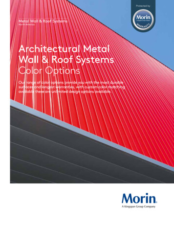
NICHIHA INSTALLATION GUIDE FOR SIX-FOOT HORIZONTAL PANELSNICHIHA ARCHITECTURAL WALL PANELSGENERALINSTALLATION GUIDESIX-FOOT HORIZONTAL PANELSTABLE OF CONTENTSBasicsLimitations, Technical Reviews, SpecialApplicationsSafetyFraming & SheathingContinuous InsulationWeather Resistive BarriersProduct InspectionStorage & HandlingFasteners344566667Hardware & Accessories 8Planning & Layout10Installing the Starter Track 11General Panel & Accessory BasicsPanel SelectionSealing Cut Panel EdgesCutting Ultimate ClipsFinish Clip UsageSealant Joints/Caulking121212131415Panel Installation 16Structural Insulating Panels18Pre-Engineered Metal Buildings18Inside Corners, Windows, & DoorsInside CornersWindow SillsWindow/Door JambsWindow/Door HeadersOutside Corners191920212222Vertical Control/Expansion Joints25Horizontal/Compression Joints26Garage Doors & Other Openings27Penetrations, Railings, & Signage27Last Course 28Gable & Overhang 28Sloped Grade/Panels Below 29Cleaning Panels 29Paint Touch-Up 29Removal of Exterior Acrylic Latex Paint30Other Paint & Graffiti Removal30Repairing Minor Damage 31Panel Replacement 322This guide is intended to provide the keyinformation needed to successfully installNichiha’s six-foot Architectural Wall Panels(AWP). Further installation informationand technical resources such as animatedinstructional videos, three-part specifications,product testing and certifications,architectural details in AutoCAD, Revit, andPDF versions, and other technical documentsare available on our website:Nichiha.com/resources.Install products in accordance with the latestinstallation guidelines and all applicablebuilding codes and other laws, rules,regulations and ordinances. Review allinstallation instructions and other applicableproduct documents before installation.
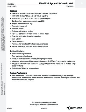
BASICS OF THE SIX-FOOT AWPSYSTEMNichiha six-foot AWP dimensions are 455mm (h)x 1,818 (l) x 16, 18, or 21mm(t). It is important tokeep in mind the actual metric dimensions whenconsidering panel layout, placement of controland compression joints, and with respect to sizingwindow and door openings. Nominal dimensions(18 inches (h) x 6 feet (l) x 5/8, 3/4 or 7/8 inches(t)) should only be used for conceptualization andgeneral understanding purposes. (Fig. 1)Panel edges are shiplapped and a factory sealant gasket is included on the top and rightedges of six-foot panels. When the panels fittogether, all factory joints are sealed. AWPattachment hardware engages the top andbottom panel edges, holding the panels off thesubstrate surface by 10mm ( 3/8”) and creatinga closed-joint, drained/back-ventilated rainscreen system with concealed fastening. Whenaccounting for the overall thickness of the AWPsystem, add this 10mm plus the thickness of thepanel (16, 18, or 21mm) for a total system thickness of 26, 28, or 31mm.Six-foot panels may only be installed horizontally.Fig. 1PANEL FRONT16mm[5/8"]455mm[18"]1818mm[6']PANEL ON PANEL DETAILSCALE: 1" 1'-0"PANEL SECTION3
NICHIHA INSTALLATION GUIDE FOR SIX-FOOT HORIZONTAL PANELSLIMITATIONS, TECHNICAL REVIEWS& SPECIAL APPLICATIONSSAFETYNatural limitations on product usage areinherent to any cladding product’s design,physical characteristics, and attachmentsystem. Nichiha AWP are intended as a lowto-mid-rise cladding product and are not foruse on high-rise buildings. Do not use AWPon open screen walls.As with any natural stone, masonry, orconcrete based product, when cutting,drilling, sawing, sanding, or abrading fibercement cladding, proper safety measuresmust be taken due to the potential forairborne silica dust, an OSHA-identifiedhazardous substance that can pose seriousmedical risks.Any project of more than three stories or 45feet, as well as those located in high windcoastal areas (Exposure Categories C and Dwith Basic Wind Speed in excess of 130 mph),requires a technical review by Nichiha toevaluate feasibility via our Technical Reviewand Special Application Form (SAF) process.By evaluating a project’s unique criteria anddesign, we can reference independentlytest-derived and calculated wind loadperformance data for our products todetermine whether and how the panels cansafely be installed on the project. Contactyour local rep or Nichiha technical departmentfor details or to initiate an SAF.AWP are not to be used in any applications/uses not specified or described in thisinstallation guide or other Nichiha technicaldocuments. Any such use shall not be backedby the manufacturer’s product warranty.Please contact Nichiha Technical Services andInstallation Support for assistance.4Always wear safety glasses and a NIOSH/OSHA approved respirator with a rating of N,O, or P 100. Carefully follow the respiratormanufacturer’s instructions as well asapplicable governmental safety regulationsconcerning silica. Refer to Nichiha’s (M)SDSfor more information.Always cut fiber cement panels outside or in awell-ventilated area. Do not cut the productsin an enclosed area.Use a dust-reducing circular saw withdiamond-tipped or carbide-tipped fibercement saw blades.Always clean panels after cutting. Fibercement dust can potentially bind to the panelfinish.
FRAMING & SHEATHINGREQUIREMENTSNichiha AWP cladding may be installed onwood or steel framing, concrete/masonrywith furring, Structural Insulating Panels (SIP),and pre-engineered metal buildings (PEMB)meeting the following requirements:Prior to Nichiha installation, closely inspectexterior wall substrate and correct anyproblems. Walls that are out of plumb,for example, can negatively impact theinstallation quality of AWP. Nichiha Spacermay be used in conjunction with panelattachment hardware if necessary to ensurean even substrate.Wood StudsSize: minimum 2x4 studsSpacing: 16” o.c maxSheathing: none, exterior grade minimum7/16” plywood/OSB (APA rated), ½” or 5/8”gypsumMetal StudsGauge: minimum 18 (20 gauge acceptablewith 7/16” plywood/OSB sheathing if localcode allows)Spacing: 16” o.c maxSheathing: none, exterior grade minimum7/16” plywood/OSB (APA rated), ½” or 5/8”gypsumConcrete/MasonryFurring is required for installation of AWPover concrete and masonry structures.Wood Furring: pressure treated lumber 2x4or 5/4x4’s, oriented vertically, spaced 16” o.c.maxMetal Furring: hat channel, c-stud, or z-furring,minimum 18 gauge with 1-2” flanges, orientedvertically, spaced 16” o.c. maxStructural Insulating Panels (SIP)SIPs should be installed in accordance withmanufacturer’s instructions and local buildingcodes. Additional special Nichiha installationrequirements for SIPs are discussed in theFasteners and Installing the First Coursesections to follow. For installations greaterthan one story, contact Technical Departmentfor assistance.Pre-Engineered Metal Buildings (PEMB)Metal buildings must be new construction.No retrofits/remodels. Metal R-panels mustbe installed reversed with ridges facing theinterior and ribs spaced no more than12” O.C.Exposure Category B AreasFully enclosed metal buildings must haveminimum 24 gauge, 50 ksi yield strengthmetal R-panels.Partially open buildings, such as those withopen bays, must have girts every 3’ withminimum 18 gauge R-panels.Building height can be no greater than30 feet.Exposure Category C AreasWainscot style installations up to three panelcourses are acceptable in Exposure CategoryC areas without additional requirements.For installations taller than 3 courses, contactNichiha technical department for assistance.Additional special Nichiha installationrequirements for PEMBs are discussed in theFasteners and Installing the First Coursesections to follow.5
NICHIHA INSTALLATION GUIDE FOR SIX-FOOT HORIZONTAL PANELSCONTINUOUS INSULATIONPRODUCT INSPECTIONWhere exterior/continuous insulation is used,AWP may be installed directly over up to1” of foam plastic insulation, depending onsheathing type. Amounts greater than oneinch require a structural solution to provideattachment points for the AWP system suchas a furring grid or third-party specializedsystem. Please contact Nichiha technicaldepartment for further assistance.Inspect all products thoroughly prior toinstallation. Do not install any product whichmay have been damaged in shipment orappears to have a damaged or irregularfinish. Should you have a question or problemwith your order, contact your local dealeror Nichiha Customer Service, toll-free, at1.866.424.4421.WEATHER RESISTIVE BARRIERSSTORAGE AND HANDLINGA weather resistive barrier (WRB) is requiredwhen installing Nichiha panels. Use anapproved WRB as defined by the 2015 IRC.Refer to local building codes.Panels must be stored flat and kept dry beforeinstallation. Refer to storage informationincluded on product pallets.A breathable WRB is highly recommendedwhen installing Nichiha panels for residentialapplications.Breathable WRB is required for all commercialapplications. However, fluid applied WRB isacceptable.All openings must have appropriate flashingto prevent moisture penetration.Follow manufacturer’s guidelines and all localbuilding codes.Fig. 26If panels are exposed to water or water vaporprior to installation, allow to completely drybefore installing.Panels MUST be carried on edge. Do notcarry or lift panels flat. Improper handling maycause cracking or panel damage.Direct contact between the panels andthe ground must be avoided at all times.It is necessary to keep panels clean duringinstallation process.The custom color finish of Illumination Seriespanels requires 30 days to fully cure andextra care must be taken to avoid damageto the paint during the installation process.Cut the panels with the face down. Alwaysclean panels with a clean, soft, dry cloth aftercutting as dust may bind to finish.
FASTENERSALL APPLICATIONSFasteners must be corrosion resistant.Stainless steel or corrosion resistant coatedscrews such as hot-dipped zinc or ceramic arerecommended. Comply with all local buildingcodes for fastener requirements.STRUCTURAL INSULATING PANELS (SIP)One inch, full-thread, corrosion resistant woodscrews must be used.WOOD STUDSFasteners must penetrate stud or sill plate aminimum of 1”.Double fastening per each Nichiha clip(minimum of 4 screws per JEL777/787 clip)is required as there are fewer or no studs tosecure the system.METAL STUDSScrews must penetrate stud or sill plate aminimum of 1/2”.Three threads are needed for effective grab.CONCRETE/ MASONRYFurring to Masonry: Use corrosion resistantmasonry screws or pneumatic masonry pinsand penetrate the furring strip and CMUthe appropriate distance in accordance withbuilding codes.Fasten starter track every 16” max.PRE-ENGINEERED METAL BUILDINGS(PEMB)Screws must penetrate reversed R-panel aminimum of 1/2”.Three threads are needed for effective grab.Fasteners must be spaced 12” o.c. into metalR-panel ribs.AWP to Furring: Screws must penetrate woodfurring a minimum of 1” or steel by ½”.Fig. 37
NICHIHA INSTALLATION GUIDE FOR SIX-FOOT HORIZONTAL PANELSINSTALLATION HARDWARE & ACCESSORIESSTARTER TRACKStarter Track serves as the foundational support for the AWP system whilealso providing faster and greater ease of installation.Horizontal Panels (6’): Starter Track FA 700ULTIMATE CLIPUltimate Clips sit on the panel shiplaps, securing AWP to the wall anddistributing dead loads to the structure. Together, Ultimate Clips andStarter Track hold the back surface of the panels off the substrate to createa 10mm (3/8”) rainscreen space.JEL 777 Clip Compatible with 16mm (5/8”) AWPJEL 787 Clip Compatible with 18 & 21mm (3/4” & 7/8”) AWPJoint Tab Attachments are included with Ultimate Clips and are securedwithin a clip at the bottom of each vertical joint to support panel lateralstability. Fasteners are included for use with the Joint Attachments only.FINISH CLIP (OPTIONAL)The Finish Clip provides an alternative to face fastening of AWP at certaintermination points where the panel shiplaps are removed. Install over 5mmSpacer. Refer to Finish Clip Usage section for general instructions.JE 310 Finish Clip – Compatible with all AWPCORRUGATED SPACERAt termination points where Panel Clips cannot be used, Nichiha Corrugated Spacer is required to maintain the rainscreen space and prevent paneldeflection at face fastening locations such as window sills and headers.FS 1005 Spacer - 5mmFS 1010 Spacer – 10mm8
SEALANT BACKERSNichiha Sealant Backers provide exact spacing for expansion andtermination joints and the recommended depth of sealant (75-80%).They provide faster installation than a foam backer rod and require lesssealant. At sealant joints, use a sealant that complies with ASTM C-920.Higher quality polyurethane or hybrid sealants are preferred.Single Flange Sealant Backer: FHK 1017 – 10 mmDouble Flange Sealant Backer: FH 1020 – 10 mmPANEL CORNERSNichiha outside panel Corners are manufactured mitered panel cornersavailable in the same finishes as all horizontally oriented AWP. Corners have3-1/2” returns (face dimension).METAL TRIM OPTIONSNichiha metal trim provides aesthetically pleasing design options forcorners, openings, and transitions, as well as vertical joints.TRIM APPLICATIONSCorner Key Outside CornersH-Mold Vertical JointsOpen Outside CornerOutside CornersBead Reveal Vertical JointsJ-Mold TerminationsL-Trim TerminationsESSENTIAL FLASHING SYSTEMStarter*Compression JointOverhang*APPLICATIONSBase/Clearance ConcealmentHorizontal/Compression JointsFascia-to-Soffit Transitions*Inside and outside corner segments are available.9
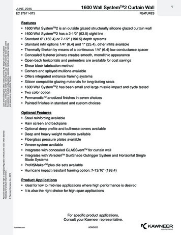
NICHIHA INSTALLATION GUIDE FOR SIX-FOOT HORIZONTAL PANELSPLANNING & PANEL LAYOUTTo ensure a successful installation, it isimportant to first plan how the panels will belaid out, where compression and control jointswill be located, and line of sight regardinginside corners decided.Reminder: Six-foot AWP actual dimensionsare metric: 455mm (h) x 1,818mm (l).Layout: Six-foot AWP can be installedin a stacked bond or a staggered bondapplication.Vertical Control/Expansion Joints: 10mm(3/8”) sealant joints account for thermalexpansion in the lateral dimension. These areoften, where possible, aligned with windowor door jambs, downspouts, or other featuresin order to minimize their appearance.Depending on sheathing type, additionalframing, furring, or blocking may be required.Horizontal/Compression Joints: ½” (min.)horizontal, flashed break detail to allow forbuilding compression at floor lines.Inside Corner Line of Sight: Sealant joints atinside corners can be placed out of view fromthe primary line of sight of a wall. Place thesealant joint on the less-viewed corner wall.CUT PANELS: In general, it is best to avoidcutting AWP to short or narrow strips andsegments of less than 9”. Specifically, whenan individual panel is wider than a windowor other opening and is used over the heador under the sill, do not cut it to less than9” in height. (see image A)When an opening is wider than an individualpanel and two or more are needed to capover the header or cup the sill, do not cutthe panel to less than 4” in height.(see image B)A9"B104"
SIX-FOOT HORIZONTAL PANELS:INSTALLING THE FA 700STARTER TRACKALL APPLICATIONSThe Nichiha Starter Track (FA 700) must belevel and attached at a minimum of 6” abovefinished soil grade or per local building codes(use a laser level to verify). When installingover a hard surface such as driveways orsidewalks, a 2” clearance is acceptable.Essential Starter Flashing may be installedprior to the Starter Track to conceal theclearance gap above hardscape and decking.Beginning with outside and inside cornersegments, fasten Flashing at each studlocation or every 10” o.c. to sill plate. FastenFlashing inside and outside corner segmentto framing on both sides, keeping at least 1”from vertical edges. Main segments will slideinto/overlap the corner segments. The AWPbottom face edge will extend ¾” below theStarter Track. Position Flashing and/or StarterTrack to leave 1/4” clearance between thepanel edge and Flashing.Fig. 22The Starter Track must be installed usingcorrosion resistant fasteners. Locate and markthe studs.WOOD & METAL STUDS OR FURRINGStarter Track must be secured at everystud line.CONCRETE/MASONRYWhen installing over concrete construction,the wall must be furred out with pressuretreated lumber or metal hat channel.Starter Track must be secured at eachfurring location.STRUCTURAL INSULATING PANELS (SIP)Secure Starter Track every 16” o.c. max.PRE-ENGINEERED METAL BUILDINGS(PEMB)Fasten Starter Track at every reversed R-panelrib at 12” o.c. max.Essential StarterFlashing11
NICHIHA INSTALLATION GUIDE FOR SIX-FOOT HORIZONTAL PANELSGENERAL PANEL& ACCESSORY BASICSAll trim, Single and Double Flange SealantBacker should be installed before panels.Refer to Inside Corners, Doors, & Windowsand Vertical Expansion Joints sectionsrespectively.PANEL SELECTIONSEALING CUT PANEL EDGESNichiha six-foot AWP are packaged with twopanels in a pack, which are placed on palletsconsisting of two stacks. Due to alternatingpatterns of texture and color betweenindividual panels as well as how the panelsare manufactured and packaged, it is best toinstall all panels from each individual stackbefore taking and installing panels from thesecond stack on the same pallet. Do notalternate installing from one stack and thesecond, which may result in undesirablepatterns.When cutting AWP, it is best to cut with thepanel face down, except when cutting brickfinish panels as it is easier to follow thesimulated mortar lines on their face.Fig. 231612Cut and exposed panel edges must be primedor sealed with fiber cement sealer (e.g.DryLock ) or paint such as Kilz Premium or Kilz Max . Do not use Illumination touchup paint for edge sealing as there will not besufficient supply for larger projects. Be sure toclean panels with a clean, dry soft cloth aftercutting to prevent dust from bonding to thefinish.
Fig. 24CUTTING ULTIMATE CLIPSJEL777/787 Panel Clips are 26” long. Wherefull length clips can be used, they arerequired. However, there may be conditionswhere clips must be cut to accommodatepanels or corner pieces in smaller areas orsegments such as narrow columns, pilasters,or insets, recessed openings, or small areasbetween windows.Notches on the upward panel engagementflanges indicate where clips can be cut evenlyinto thirds. These 1/3 segments can be furtherreduced evenly into two or four pieces eachwith weep holes serving as dividing points.The smallest segment must include at leastone downward panel engagement flange.Always use the widest clip segment possible.Cut with a non-ferrous saw blade on a band orchop saw.Fig. 2513
NICHIHA INSTALLATION GUIDE FOR SIX-FOOT HORIZONTAL PANELSFINISH CLIP USAGEFig. 27The Finish Clip requires added preparation ofthe panels with the use of a biscuit joiner:1. To route grooves into the top edge ofa panel, use a biscuit/plate joiner, suchas Makita’s PJ7000. A carbide blade isrecommended.2. Set the biscuit joiner’s angle guide at zerodegrees and height to ¼”.Fig. 283. Set the depth of groove for a size 20biscuit to ensure the grooves are wideand deep enough for JE310 clips to seatproperly, ¼” from the back/unfinished faceof the panel.4. Route the cut edge with the unfinishedpanel surface facing up, lining the groovesup with stud locations (16” o.c. maximum).5. The clip should fit snug but not too tightlywhen placed on the panel. Cut, routedpanel edges must be sealed with 100%acrylic latex primer or paint.Fig. 2614"[6 mm]12"[12 mm]PanelFront14PanelBackFig. 29
SEALANT JOINTS/CAULKINGFig. 30Fasten Single Flange Sealant Backers at insidecorners (one wall at corner), along windowand door jambs, and transition points withother cladding. Fasten to framing, blocking orplywood/OSB sheathing at 12-14” o.c. withthe 3/8” bump/sealant portion butting thecorner or jamb.Sealant complying with ASTM C-920 isrequired where Single and/or Double FlangeSealant Backer is used.Refer to the sealant manufacturer’sinstructions or requirements.Place low-adhesive tape (masking or painter’s)over the panel along the areas requiringsealant joints for a clean caulk line.Fill the gap between the panels with a colormatched/coordinating sealant which complieswith the ASTM C-920 standard. NichihaSealant Backers allow for the proper depth ofsealant (75-80%).Before removing tape, press the surface of thesealant with a caulk spatula or similar tool toensure an even surface. Remove masking tapebefore sealant cures. If excess sealant adheresto panel, remove completely using a puttyknife or soft cloth.15
NICHIHA INSTALLATION GUIDE FOR SIX-FOOT HORIZONTAL PANELSSIX-FOOT HORIZONTAL PANELINSTALLATIONAWP installation proceeds by workingfrom left to right.Wood, Metal, Concrete/Masonrywith FurringFor six-foot AWP, trim off the left side shiplapped edge so the panel will fit tightlyagainst an already installed inside cornerspacer, Sealant Backer, or outside corner trim.If starting at an inside corner, predeterminewhich wall will include the Single FlangeSealant Backer for an inside corner detail.Consider the location to minimize the visibilityof the sealant joint line. Clad the highervisibility wall without the sealant joint first sothat the adjoining wall panels can terminateto it with the Single Flange Sealant Backerdetail.Set first panel into the Starter Track andsecure the top edge with a Panel Clip, placingthe first clip about one inch from the left edgeof the panel. Fasten clip at each stud locationthe clip reaches. Every clip will cover 2-3studs and must be fastened to each.(Figure 31-32)Proceed along the panel to the right, placinganother clip 3-4 inches from the end of thepreviously installed clip so that the secondclip is roughly centered over the panel middlebut DO NOT skip any studs. Fasten clip ateach stud location.Place the second panel next to the first,making sure the shiplap joint fits tightlytogether.16A rubber mallet or block of wood may beused to seat the panels firmly in place andtighten to the left. Do not hammer directlyanywhere on the panels as direct contact maycause cracks, gouges, or chipping. (Figure 33)Place a clip on top of this vertical joint.Vertical joints should be spanned with a clipcovering the top edge of where the panelsmeet. Fasten clip to each stud it reaches,again not skipping any studs. Each long paneledge should be supported by about 2.5 clips.(Figure 34)Verify the first course of panels is level. Largecommercial buildings require checking levelaround the entire building.Start the second row in the same fashionas the first, but, in addition to the previoussteps, add the Vertical Joint Tab Attachmentagainst the bottom right hand corner eachpanel. The Attachment seats inside the panelclip, with tabs that fit on clip’s rainscreenflange. Fasten the attachment to the panelclip with the provided fastener. (Figure 35)Fit panels tightly together on both horizontaland vertical joints, ensuring the panel edgesare properly butted together.Complete the second and remaining nonterminal rows in the same way, with the VerticalJoint Tab Attachments at the base of eachvertical joint. Terminal rows such as underCompression Joints or at the Last Course arecovered in subsequent sections of this guide.
Fig. 31Fig. 32Fig. 33Fig. 34Fig. 3517
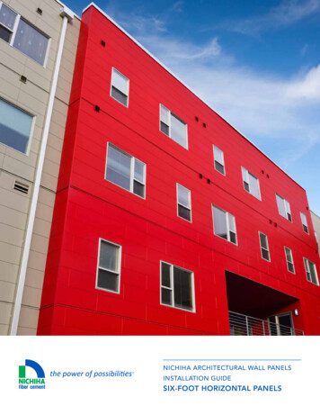
NICHIHA INSTALLATION GUIDE FOR SIX-FOOT HORIZONTAL PANELSSTRUCTURAL INSULATING PANELS (SIP)In general, the steps mirror those for stud wallapplications. However, double fastening pereach panel clip (minimum of 4 screws per clip)is required as there are fewer or no studs tosecure the system.STACKED AND STAGGEREDPANEL LAYOUTSFig. 36CENTERLINE OF FRAMING MEMBEROR CHANNEL (SHOWN AT 16" O.C.)FACE FASTEN AT TOPThere must be about 2.5 clips per six-footpanel edge, with vertical joints spanned byPanel Clips and the Joint Tab Attachmentseated in and fastened to the Panel Clip atthe lower right corner of each panel.PRE-ENGINEERED METAL BUILDINGS(PEMB)Refer again to general requirementsconcerning PEMB installations in the Framingand Sheathing Requirements section.JOINT TAB TO BEINSTALLED TIGHTLYAGAINST LOWERRIGHT HAND CORNEROF PANELJEL777/787PANEL CLIPFA700 STARTER TRACK26" CLIP PLACEMENT FOR STACKED PANEL LAYOUTFig. 37CENTERLINE OF FRAMING MEMBEROR CHANNEL (SHOWN AT 16" O.C.)FACE FASTEN AT TOPWith R-Panels installed reversed and ribsspaced no more than 12” o.c., installAWP in the same manner as with stud wallapplications but with Panel Clips fastened toeach rib they reach.JOINT TAB TO BEINSTALLED TIGHTLYAGAINST LOWERRIGHT HAND CORNEROF PANELThere must be about 2.5 clips per six-footpanel edge, with vertical joints spanned byPanel Clips and the Joint Tab Attachmentseated in and fastened to the panel clip at thelower right corner of each panel.JEL777/787FA 700 STARTER TRACK26" CLIP PLACEMENT FOR STAGGERED PANEL LAYOUT18
PANEL INSTALLATIONINSIDE CORNERS, WINDOWS,& DOORSALL APPLICATIONSAppropriate flashing should be used toprevent moisture penetration on all insidecorners, doors, and windows. Refer to localbuilding codes for best practices. Cut andexposed panel edges must be primed orsealed with fiber cement sealer or paint.Fig. 38INSIDE CORNERSSINGLE FLANGE SEALANT BACKER(FHK 1017)Fig. 39Decide primary line of sight in order tominimize visibility of the sealant joint.Install the panel (ship-lapped edges at thejoint will need to be cut off) on the front wall(more visible) first. Ensure panel is buttedup tight to the inside corner wall. Fasten theSingle Flange Sealant Backer onto the sidewall right up against the front wall panel’sedge at 12-14” o.c.Install side wall panel directly against thesealant backer and secure with Panel Clips.Fill space with sealant. (Fig. 38-40)TRIM BOARDSInstall trim boards at inside corner first andbutt cut panel edges with a minimum ¼” gap.Single Flange Sealant Backer can also be usedwhere panels butt to trim boards. Add ASTMC920 compliant sealant to the gap.Fig. 403/8" SEALANT JOINT OVER SINGLEFLANGE SEALANT BACKERNICHIHA CLIPNICHIHA PANEL19
NICHIHA INSTALLATION GUIDE FOR SIX-FOOT HORIZONTAL PANELSWINDOW SILLSJE310 FINISH CLIPFor recessed windows, add a flashing wherethe panels will terminate so the top edges arecovered or capped at the sill.Remove the top ship-lapped edge of thepanel at the window sill, cutting the panel tothe required height, and route grooves intopanel top at appropriate width to coincide withframing members. (Refer to Finish Clip Usagefor biscuit joiner info.) Clean any dust off thepanel. For windows narrower than a panel,only remove the portion of the panel edgedirectly under the window but accounting for aminimum ¼” gap at both jambs.Cut, routed panel edges must be sealed with100% acrylic latex primer or paint, such asKilz Premium or Kilz Max. Panel edge shouldbe spaced a minimum 3/8” below a flush oroverhanging window sill to accommodate theFinish Clip.Fasten FS1005 Corrugated Spacer (5mm) atstud locations before setting panel into place.Seat Finish Clips into grooves and fasten ateach stud location, through Spacer, to securepanel into place.If the top edge of the panel is fully shelteredunder the sill, it is not necessary to seal the3/8” gap. For better system performance,Nichiha recommends the vented approach.(Figure 41)Fig. 41FACE FASTENING (J-MOLD OPTIONAL)For recessed windows, add a flashing wherethe panels will terminate so that the topedges are covered or capped at the sill. Asneeded to match the window width, removepanel top ship-lapped edge, cutting the panelto the required height to fit below the windowsill, leaving a ¼” gap between the top of thecut panel edge and the window sill or trimboard.Cut, routed panel edges must be sealed with100% acrylic latex primer or paint, such as KilzPremium or Kilz Max. Clean any dust off thepanel with a clean, doft, dry cloth.Add FS1010 Corrugated Spacer (10mm) atstud locations, set the panel on the clips ofthe panel(s) below, and then face fasten top,cut edge of panel at the sill. Keep screws 1”below panel edge. This will avoid cracking orbreaking the panel. Best practice is to predrill the panel before fastening.If the top edge of the panel is fully shelteredunder the sill, it is not necessary to seal the1/4” gap. For better system performance,Nichiha recommends the vented approach.(Figure 42)J-Mold or other trim channels can be includedat a sill but must be placed on the panel edgeprior to face fastening panel so that the trimis fastened simultaneously.Fig. 42OPTIONAL SEALANT - NICHIHAPREFERS NO SEALANT FOR VENTINGPURPOSES (SEE INSTALLATION GUIDE)FINISH CLIPOVER 5MM SPACERFACE FASTENERNICHIHA 10MM SPACER20
WINDOW/DOOR JAMBSA minimum gap of 1/4” is required whenbutting panels into windows, doors, andtrim boards.SINGLE FLANGE SEALANT BACKER:Install the Single Flange Sealant Backer first,butting to the door/window jamb or trimpieces prior to installing the panels.The Single Flange Sealant Backer must befastened a minimum of 12” to 14” o.c. tostuds, blocking, or structural sheathing.Cut panel to appropriate width, at leastremoving ship-lapped edge. Remember toclean freshly cut panels with a soft, dry cloth.Install panels and fill gap with ASTM C-920compliant sealant. (Figure 43)Fig. 43Single Flange Sealant BackerJ-MOLD: Pre-install J-Mold trim with a ¼”gap between it and the window/door jamb.Panels must fit completely within trim, withno exposed panel edges, but leaving a 1/8”space between panel edge and J-Mold. Placefoam backer rod inside the channel to helpcreate this gap.Lastly, add closed-cell foam backer rod andsealant to the ¼” gap between the J-moldand jamb.NICHIHA CORNERS AT RECESSED JAMBS:Nichiha Corners can be used to wrap recessedwindow jambs. Corners have returns of 3-1/2”(face dimension). Cut piece as needed forshallower returns.Wrap base of jamb with cut pieces of StarterTrack (or FS1010 Spacer if face fastening)Install Corner pieces at jamb prior to mainpanels using cut Panel Clips (refer to CuttingPanel Clips section)
Inside Corners, Windows, & Doors 19 Inside Corners 19 Window Sills 20 Window/Door Jambs 21 Window/Door Headers 22 Outside Corners 22 Vertical Control/Expansion Joints 25 Horizontal/Compression Joints 26 Garage Doors & Other Openings 27 Penetrations, Railings, & Signage 27 Last Course 28 Gable & Overhang 28 Sloped Grade/Panels Below 29