Transcription
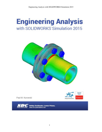
IJCSI International Journal of Computer Science Issues, Vol. 10, Issue 2, No 2, March 2013ISSN (Print): 1694-0814 ISSN (Online): 1694-0784www.IJCSI.org305Design and Simulation of Gate Driver Circuit Using PulseTransformerDaizhuang Wang1, Haifeng Dai1 and Zechang Sun11Clean Energy Automotive Engineering, Tongji UniversityShanghai, 201804, ChinaAbstractPulse transformer is always used to be the isolator between gatedriver and power MOSFET. There are many topologies about theperipheral circuit. This paper proposes a new topology circuitthat uses pulse transformer to transfer driving signal and drivingpower, energy storage capacitor to supply secondary side powerand negative voltage. Without auxiliary power source, it canrealize rapidly switch and off state with negative voltage. And asimulation model has been used to verify it. The simulationresults prove that the new driver has a better anti-interference,faster switching speed, lower switching loss, and higherreliability than the current drive circuits.Keywords: pulse transformer, gate driver circuit, PowerMOSFET, PSPICE simulation.1. IntroductionWith the development of the full-controlled semiconductordevices, Power MOSFET (Metal Oxide SemiconductorField Effect Transistor) has been applied widely in SwitchPower Supply Technology, for whose characteristics offast switching speed, good performance in high-frequency,low driver energy loss and easy to parallel. PowerMOSFET is nearly an ideal switch, which has a high gainand fast switching speed. However, the parasiticcapacitances existing in the Power MOSFET degradeperformance of switch [1] [2].The switch process of Power MOSFET is the chargedischarge of the parasitic capacitances shown in Fig. 1. Inorder to decrease the influence of these parasiticcapacitances, the gate driver circuit should meet the followdemands [3].1. Trigger Pulse should rise and fall fast enough todecrease switching loss.2. To reduce the Drain-to-Source drop voltage Vds whenon state, sufficiently high gate-to-source voltage Vgs needto be supplied to guarantee Power MOSFET deeplysaturated.3. To ensure reliable turning off when off state, negativevoltage should be provided to avoid unexpected turning oncaused by electromagnetic interference.4. Sufficient power should be able to provide to meet therequired turn on energy.Consideration of safety in most cases, the gate drivercontroller should be isolated to Power MOSFET.Therefore, pulse transformer is often used as an isolatorthat transfers driving signal and energy without auxiliarypower source [4] [5] [6]. This paper designs a new gatedriver circuit also using pulse transformer.2. Gate Driver Circuits Using PulseTransformer2.1 Conventional DriverDrainCgdCdsGateCgsSourceFig. 1 Equivalent circuit showing parasitic capacitance: the capacitancebetween the Gate and Source Cgs, the capacitance between the Gate andDrain Cgd, the capacitance between Drain and Source Cds.R1CTRgVDPWMControllerGNDFig. 2 Conventional driver circuitFig. 2 shows the conventional driver circuit [3]. Theblocking capacitor C is placed in series with the primaryCopyright (c) 2013 International Journal of Computer Science Issues. All Rights Reserved.
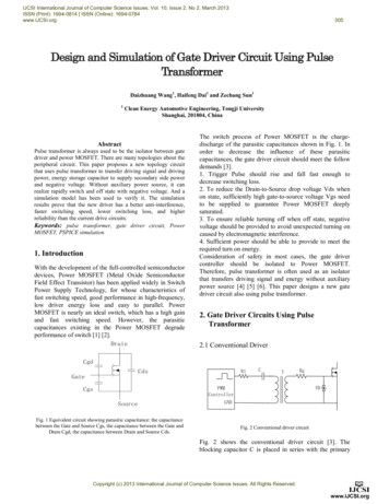
IJCSI International Journal of Computer Science Issues, Vol. 10, Issue 2, No 2, March 2013ISSN (Print): 1694-0814 ISSN (Online): 1694-0784www.IJCSI.orgwinds of the pulse transformer to provide the reset voltagefor the magnetizing inductance. Without the capacitorthere would be a duty ratio dependent DC voltage acrossthe winding and the transformer would saturate. However,the blocking capacitor C and the magnetizing inductancewill excite the L-C resonance. In most cases this L-Cresonance can be damped by primary resistor R1.Bidirectional Zener diode VD is used to decrease theovershoot of the gate voltage Vgs. The gate resistor Rg isused to avoid the gate transient surge current. This kind ofgate driver has advantages of simple structure, easy to beintegrated while the amplitude of its output voltage reduceswith the duty ratio increase. So the conventional driver isnot suitable for working in large duty ratio.2.2 Modified DriverC1R3R1R4C2306R5D1R2R6C3M1TX112VdcV1D2D3 Q1C5C4R7L2L1R80Fig. 3 Modified Driver CircuitA modified transformer-isolated gate driver circuitsimulation model is shown in Fig.3. The pulse transformermodel consists of ideal transformer TX1, primary windingresistor R4, secondary winding resistor R5, transformerleakage inductance L1, L2, and distributed capacitance C1,C4, C5. Here, a bootstrap capacitor C3 and a bootstrapdiode clamp D3 are used to restore the original gate driveamplitude on the secondary side of the transformer. WhenPWM signal turns low, the PNP transistor Q1 is used toaccelerate the discharge of Cgs, and resistor R6 is not onlyused to maintain the base-to-emitter voltage of Q1 thatensures Q1 to be on state, but also provides a dischargechannel that will make collector-to-emitter voltage of Q1down to zero. Secondary resistor R1 with bootstrapcapacitor C3 and bootstrap diode D3 together constituteRCD absorbing circuit, which can suppress the resonancecaused by leakage inductance. This driver provides acertain negative voltage to improve reliability of the offstate reduces off-time and switch energy loss and has agood performance on widely range of duty ratio. However,it hardly reduces the rise-time and is sensitive to leakageinductance. So this kind of driver needs to be improved [3].2.3 New 5M1D3D512VdcR70Fig. 4 New DriverCopyright (c) 2013 International Journal of Computer Science Issues. All Rights Reserved.R8
IJCSI International Journal of Computer Science Issues, Vol. 10, Issue 2, No 2, March 2013ISSN (Print): 1694-0814 ISSN (Online): 1694-0784www.IJCSI.orgThis paper proposes a new gate driver circuit using pulsetransformer that can provide negative voltage for off state,store energy to accelerate turning on. Fig. 4 shows thesimulation model of the new driver. Here, pulsetransformer model consists of ideal transformer TX1,primary and secondary winding resistor R3, R4, leakageinductance L1, L2, distributed capacitor C1, C5, C6.Compared to the modified driver, the new driver is added aseries of components, includes energy storage capacitor C7,C4, totem pole constituted by NPN transistor Q1 and PNPtransistor Q2, Zener diode D3 and simply diode D1. WhenPWM signal rises, C7 charges C4 and the gate firstly. Withthe process of gate charging, the voltage of C7 is graduallydecreasing while the voltage of bootstrap diode D4 isincreasing. After the two voltages equal, C7, C4 and Cgsall began to be charged by the voltage of bootstrap diodeD4 until close of PWM signal rising. When PWM signalfalls, Q1 turns off but Q2 turns on. Then, C4, which ischarged from the C7 and transformer when PWM is high,supplies the negative voltage to gate-source capacitor Cgsthrough Q2. Zener diode D3 and simple diode D5 are usedto control the voltage of C4. It can realize differentnegative voltage by changing the parameter of Zener diodeD3.3. Parameters Analysis3.1 Pulse TransformerPulse transformer would be saturation if the current acrossit continues in a long duration [7] [8] [9]. In order to avoidsaturation, the magnetizing inductance of the pulsetransformer must be increased to decrease the magnetizingcurrent. Therefore, the size of pulse transformer will belarge. However, too large size goes against circuitintegration. It is an optimization that alternates the cycletime and transformer size. In this paper, a new pulsetransformer with one primary winding and two secondarywinding was designed. The primary and secondarywindings of it all had same numbers of turns.3.2 Secondary side capacitorsSecondary side capacitors include bootstrap capacitor C3,energy storage capacitor C7, C4.C4 is charged when PWM is high, ideal charged voltageVC 4 VD 3 VF VEC . Where, VD3 is the voltage of D3, VFis the forward drop voltage of D5, and VEC is the emitterto-collector voltage of Q2.When PWM signal turns to low,C4 charges the Cgs reversely.That is,307C4 *(VC 4 VC 4 ') Qg Ciss *(VC 4 ' VF VEC )V 'Where, C 4 is the negative voltage of C4, Qg is the gatecharge total, Ciss is the equalization input capacitor ofPower MOSFET. In according to these analyses, the valueof C4 and D3 can be calculated. Limited to the charge time,C4 hardly charge enough when PWM signal duty ratio issmall. So it only can provide a low level negative voltageas shown in Fig. 10.C7 is used to supply the gate charge when PWM signalrises, and to be charged when PWM is on state. So thevoltage of C7 varies in a cycle, which will impact on thetransient response of the new driver circuit. Therefore, thevalue of C7 is always 5% 10% of C3.Too large value of C3 will cause that the driver circuitcan’t restore the amplitude of original PWM signal. Buttoo small value of C3 will cause Vgs decreasing, whichleads poor immunity. Generally, the value of C3 should belarger than the sum value of C7 and C4.3.3 Blocking capacitorThe value of the blocking capacitor C2 directly determinesripple and amplitude of the drive current across it. Thecurrent needed to turn on Power MOSFET is,I drv I g I C 3That is,Qg U C 3UD 2 (1 D) C3C2 2 U C 2 U C 2 4( LT 1 L1 ) f U C 2(1)The value of C2 is not only limited to Eq. (1), but alsolimited to transient response of the driver circuit. Therefore,the accuracy value of C2 needs to be more or less adjusted.3.4 Matched load resistanceThe matched load resistance includes primary resistor R2and secondary resistor R3. In the primary circuit, primaryresistor R2, primary winding resistor R3, PWM controlleroutput resistor Rdrv, primary magnetizing inductance LT1,leakage inductance L1 and blocking capacitor C2 togetherform a RLC 2-order oscillation circuit [3].Damping coefficient,( R2 R3 Rdrv )C22( LT 1 L1 )Too small value of ξ will cause Vgs overshoot, but toolarge value of ξ , that means R2 in a large value, willξ Copyright (c) 2013 International Journal of Computer Science Issues. All Rights Reserved.
IJCSI International Journal of Computer Science Issues, Vol. 10, Issue 2, No 2, March 2013ISSN (Print): 1694-0814 ISSN (Online): 1694-0784www.IJCSI.orgcause too large partial voltage of R2. Generally,slight less than 1.That is,ξis3084.1 Steady-state responseDuty Ratio 0.1, f 100kHz, Iload 5A,Dload 12VPWM( LT 1 L1 ) R3 RdrvC2.Secondary resistor R1, secondary winding resistor R4,secondary inductance LT2, secondary leakage inductanceL2, bootstrap capacitor C3, and bootstrap D4 togetherconstitute another RLC 2-order oscillation circuit insecondary side. When PWM controller happens to powerinterruption, the energy stored in the secondary windingwill continue to charge C3 until the negative voltage ofsecondary winding is down to 0. It maybe leads PowerMOSFET unexpected turning on. Secondary resistor R1 isused to decrease the voltage of C3 by providing adischarge channel. Generally, its value is 1k ohm.15Vgs / VR2 210New Driver0-55678PWMIt can be concluded in Fig. 5 that the charge time, whichmeans the turn on time of Power MOSFET, increases withthe increase of R5. However, the area enclosed by thecharge current and charge time is constant because ofconstant Power MOSFET gate charge Qg.f 100kHz, Id 5A, Vds 12V1.2Ig / A0.80.6R5 5Ω0.4R5 10Ω0.200.10.2Time / us0.3Modified Driver105New Driver0-5012345Time / us6789(b)Fig. 6 Steady-state response in different duty ratio conditions, (a) Smallduty ratio, (b) Large duty ratio. Vgs: gate-to-source voltage; PWM signalhigh level: 15V in new driver 12V in modified driver.R5 1Ω115Vgs / VGate resistor R5 is used to avoid surge charge current,which requires the value of R5 large enough. But too largevalue will decrease the turn on time of Power MOSFET.Fig. 5 shows the gate charge current curves in differentgate resistor conditions. [10] [11].0-0.19 10 11 12 13 14 15Time / us(a)Duty Ratio 0.9, f 100kHz, Iload 5A, Vload 12V3.5 Gate resistor1.4Modified Driver50.4Fig. 5 Gate charge current curvesAs shown in Fig. 6, the two drivers all have a goodperformance in the widely range of duty ratio though theamplitude of Vgs has a certain degree of attenuation inlarge duty ratio condition. Primary magnetizing currentincreases with the increase of duty ratio. Then the partialvoltage of R2 increases, which will lead transform voltagedecrease. So Vgs is attenuated. It’s also shown in Fig. 8that the new driver can provide negative voltage to offstate, but the amplitude of the negative voltage varies withthe duty ratio. The amplitude voltage of new driver is lessthan the modified driver. And the difference will beremarkable in large duty ratio.4. Simulation resultsIn order to verify the performance of the two driver circuit,this chapter use PSPICE software to carry out a simulation.The follows are the simulation results.Copyright (c) 2013 International Journal of Computer Science Issues. All Rights Reserved.
IJCSI International Journal of Computer Science Issues, Vol. 10, Issue 2, No 2, March 2013ISSN (Print): 1694-0814 ISSN (Online): 1694-0784www.IJCSI.org3094.2 Anti-interferencef 100kHz, Iload 5A, Vload 12VDuty Ratio 0.5, f 100kHz, Iload 5A, Vload 12V, Ls 7uHPWM15Vgs / VPWMModified Driver50 New Driver-51510Modified Driver0Vds / VVgs / V201010 New Driver58161412Time / us10-54.91854.3 Switching transientf 100kHz, Iload 5A, Vload 12VVgs / V1510 New DriverModified Driver-5-0.1Vds / V tsw ( on )0tsw ( off )050Vd s ( on ) I d ( on ) dt * fVd s ( off ) I d ( off ) dt * fNew Driver00.15.54.4 Efficiency analysis Modified Driver105.4Fig. 8 shows the gate driver voltage Vgs curve and drainto-source voltage Vds curve when PWM signal turns on.The modified driver energy is only supplied by bootstrapcapacitor C3 and secondary winding. In addition to C3 andsecondary winding, the new driver energy is also suppliedby C7. So, the new driver has a larger gate chargingcurrent, which indicates steeper rising edge and shorterdelay and turn on time. Fig. 9 shows the gate driver voltageVgs curve and drain-to-source voltage Vds curve whenPWM signal turns off. Due to the negative voltagesupplied by C4, the new driver has slight larger dischargecurrent and shorter discharge response delay time than themodified driver that although it also has Q1 to provide arapid discharge channel. Overall, the new driver has amore excellent performance in response speed and turn ontime. PM5-5155.25.3Time / usThe energy loss is another import factor to evaluate theperformance of driver circuit. This paper uses a concept ofaverage power, i.e. the ratio of energy loss in a cycle andthe cycle period [12].The switch energy loss can becalculated by Eq. (2).PWM05.1Fig. 9 Turn off processFig. 7 Steady-state response using a large leakage inductance transformerFig. 6 shows the steady-state response when just thetransformer nominal leakage inductance is considered. Fig.7 shows the steady-state response when PCB tracinginductance is taken into account or a large leakageinductance transformer is used. As shown in the twofigures, the new driver has a better performance on antiinterference. Bootstrap diode D4 and totem pole worktogether to isolate the impact of leakage inductance toPower MOSFET. D4 supplies a discharge channel toleakage inductance of transformer while totem polesupplies a charge-discharge channel to Cgs. The twochannels are isolated to each other. Therefore, theoscillation generated by the leakage inductance oftransformer can’t transfer to the gate of Power MOSFET.Modified Driver0New Driver0.20.30.4Time / usFig. 8 Trun on processCopyright (c) 2013 International Journal of Computer Science Issues. All Rights Reserved.(2)
IJCSI International Journal of Computer Science Issues, Vol. 10, Issue 2, No 2, March 2013ISSN (Print): 1694-0814 ISSN (Online): 1694-0784www.IJCSI.orgf 100kHz, Vload 12V, Duty Ratio 0.5Switch Energy Loss / W10.8Modified DriverVdrv 12V0.6New DriverVdrv 15V0.40.20051015Load Current / A20Fig. 10 Switch energy lossFig. 10 shows the switch energy curves of the two driversin different drain (load) current. The switch energy loss ofthe two drivers all increase with the increase of current.However, the new driver switch energy is smaller due to itsfaster switch speed.5. ConclusionsThere are many kinds of power MOSFET Gate drivercircuit current, and each of those has its merit and demeritand applicable situation. In this paper, two kindstopologies is introduced, one is the modified driver circuitusing pulse transformer, and another one is new divercircuit. The results of simulation prove that the modifieddriver has stable driving voltage, a wide duty ratio controlrange, but its performance is sensitive to leakage and PCBtrace inductance. However, the new driver has a fasterswitch speed, shorter switch delay time and lower switchenergy loss. Furthermore, the new driver has a betterreliability because it can supply negative voltage to offstate, and has good anti-interference to leakage inductance.Overall, the new driver has a good significance inapplication.References310[5] L. Bolduc, A. Gaudreau and A. Dutil, "Saturation time oftransformers under dc excitation", Electric Power SystemsResearch 56 (2000) 95–102.[6] D. Bortis, G. Ortiz, J.W. Kolar and J. Biela, "DesignProcedure for Compact Pulse Transformers with RectangularPulse Shape and Fast Rise Times", IEEE Transactions onDielectrics and Electrical Insulation, Vol. 18, No. 4; August2011, pp. 1171-1180.[7] Patrick Scoggins, "A Guide to Designing Gate-DriveTransformers", Power Electronics Technology, January 2007,pp. 32-36.[8] Jean-Christophe Crébier and Nicolas Rouger, "Loss FreeGate Driver Unipolar Power Supply for High Side PowerTransistors", IEEE TRANSACTIONS ON POWERELECTRONICS, Vol. 23, No. 3, May 2008, pp. 1565-1573.[9] J.Cˇ. Mikulovic , · M.S. Savic, "Calculation of transients intransformer winding and determination of windingparameters", Electr Eng (2007) 89: 293–300.[10] Zhiliang Zhang, Wilson Eberle, Zhihua Yang, Yan-Fei Liuand Paresh C. Sen, "Optimal Design of Resonant Gate Driverfor Buck Converter Based on a New Analytical Loss Model",IEEE TRANSACTIONS ON POWER ELECTRONICS, Vol.23, No. 2, March 2008, pp. 653-666.Daizhuang Wang received the B.E. degree from the school ofAutomotive Engineering, Harbin Institute of Technology, Weihai,China, in 2011. Currently, he is a postgraduate in Clean EnergyAutomotive Engineering Center, Tongji University, Shanghai,China. His current interests include lithium-ion batterymanagement system, lithium-ion battery pack equalization system,DC-DC Converter, and Power MOSFET driver circuit.Haifeng Dai received his B.E. degree from the School ofMechanical Engineeing, Tongji University, Shanghai, China, in2003. He was received the Ph. D from Tongji University, Shanghai,China, in 2008. He is currently a lecturer in Clean EnergyAutomotive Engineering Center, Tongji University, Shanghai,China. His current research interests include storage batterymanagement system, wireless charging technology and DC-DCconverter.Zechang Sun received his B.E. and M.E. degree from theDepartment of Motor, Harbin Institute of Technology, Harbin, China,in 1976 and 1981, respectively. From 1986 to 1987, he was aVisiting Scholar in TH Darmstadt of Germany, where he wasengaged in research on Power Electronics and DC-DC Converter.He was received the Ph. D in “Pattern Recognition and IntelligentControl” from Tongji University, Shanghai, China, in 1988. He iscurrently a Professor in Clean Energy Automotive EngineeringCenter, Tongji University, Shanghai, China. His current researchinterests include clean energy automotive power train systemintegration and control, electro-hydraulic braking system, andStorage battery management system.[1] K.S.Oh, "MOSFET Basics", FAIRCHILD, Dev. 4, July 2000.[2] Ray Ridley, "Gate Drive Design Tips", Power SystemsDesign Europe, December 2006, pp. 14-18.[3] Laszlo Balogh, "Design and Application Guide for HighSpeed MOSFET Gate Drive Circuits", International Rectifier,Technical Paper.[4] Zhiliang Zhang, Wilson Eberle and Yan-Fei Liu, "A 1-MHzHigh-Efficiency 12-V Buck Voltage Regulator with a NewCurrent-Source Gate Driver", IEEE TRANSACTIONS ONPOWER ELECTRONICS, Vol. 23, No. 6, November 2008,pp. 2817-2827.Copyright (c) 2013 International Journal of Computer Science Issues. All Rights Reserved.
Pulse transformer is always used to be the betweenisolat gate or driver and power MOSFET. There are many topologies about the peripheral circuit. This paper proposes a new topology circuit that uses pulse transformer to transfer driving signal and driving power, energy storage capac