Transcription
Automatic Exposure ControlUsing AutomaticExposure Control inDigital Radiography A. Kyle Jones, Ph.D.U.T. M. D. Anderson Cancer CenterDepartment of Imaging Physics2008 AAPM Meeting, Houston, TXThe purpose of AEC is to deliver consistent,reproducible exposures across a wide range ofanatomical thicknesses, tube potentials, andusersDetectors used in AEC systems includefluorescent screens with PMTs/photodiodes,PMTs/photodiodes,ionization chambers, and possibly solid statedetectorsAEC System ference Voltage-3 -2 -1 0 1 2 3AmplifierComparatorLoosely based on Bushberg, Seibert, Leidholdt, and Boone, TheEssential Physics of Medical Imaging.Fundamental AEC performancecharacteristics Initial acceptance testing Sensor selector/locationDensity correctionScreen sensitivity adjustmentSensitivity vs. speed settingReproducibilityAEC balance/field sensitivity matchingAEC sensitivityPatient thickness trackingkVp tracking Beam quality correction curveBackup timerCell mappingMinimal exposure durationField size tracking*Ongoing QC testing Remember thisAEC sensitivityDensity correctionkVp trackingPatient thickness trackingReproducibilityAEC balanceBackup timerMinimum exposure durationField size tracking* Test your system at the SID for which the grid isfocused and your system calibratedAEC detectors themselves have an inherentenergy dependenceSlight variations do exist between cells andshould be evaluated upon acceptance testingTrue vignette: Siemens Sireskop system with reciprocating grid. AEC balanceconsistently failed when tested at an SID of 100 cm. Moving the tube to an SIDof 115 cm resulted in passing test. Cause: Grid reciprocation delay was set toresult in appropriately exposed images at an SID of 115 cm, where Siemenscalibrates. We were able to adjust the delay to balance the AEC cells within 10%and provide acceptable image quality at 100 cm SID.1
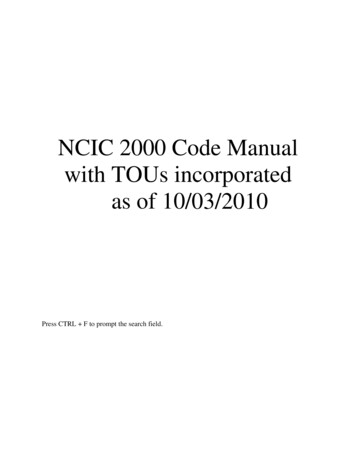
InterInter-cell differences existDensity control Unit ight68.0Left66.0 Center 60.0130Adjusts mAs upward or downward in increments of 252530% per stepSome newer DR systems do not incorporate thisfeaturePublished guidelines/recommendations 62.070.0050 64.0L R507090kVp110130kVp Tested for proper operation and similar step size (NCRP 99)0.15 to 0.30 OD per step (AAPM 74)4-step controller should adjust by 2020-25% per step (AAPM14)Fundamental differences from S/F: Absence of featureon some systems Curious that some systems still include this featureAir kerma vs. sensitivity selection Many DR systems feature selectable ‘sensitivity’sensitivity’ settingsfor imaging protocols These settings adjust the sensitivity of the AEC cellsresulting in higher or lower image receptor exposures Akin to using different speed screen/film combinations fordifferent body regions – e.g. 200 speed for chest and 400speed for general Fundamental differences from S/F: Similar toscreen selector settingPhilips DR system – Phil Rauch Resolution of EI is not sufficient to identify changesin sensitivity settingWhile no regulations or guidelines exist, it is prudent toverify that exposure varies logically and predictably withselection Inversely proportional120.0035mAs30SNR25SNR vs. Sensitivity 01020.00500200400600800100012001400Sensitivity setting16000.001800Aluminum80.00SNR Air kerma vs. sensitivityRefers to AEC, not digital detectormAsSNRUnit 1100.0060.0040.0020.00mAs 2 mAs1 S1S20.0002004006008001000120014001600Sensitivity2
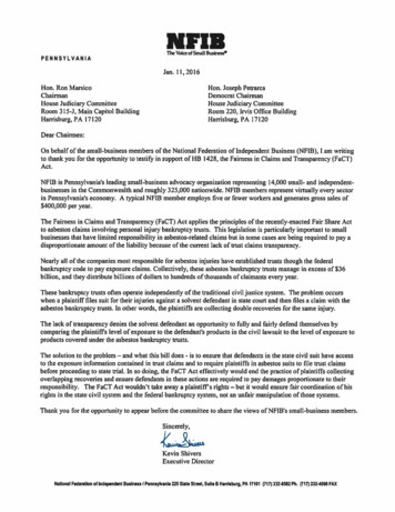
Common AEC balance schemesAEC Balance Field sensitivity matchingTo achieve consistent exposures, AEC cellsshould be balancedManufacturers of xx-ray systems use severaldifferent schemes for AEC balancingThus, a oneone-sizesize-fitsfits-all test will not be valid ifyou work with a variety of systemsFundamental difference from S/F: Somemanufacturers have changed schemes111AEC Balance Test AEC balance during acceptance testing to set a baselinestandard for balanceAsk your service engineer about the calibration/balancingprocedure Many manufacturers today use AEC systems that are not serviceableserviceable forbalance – they can only be replacedIn this case you are stuck with manufacturer’manufacturer’s balance schemeOther manufacturers still have tunable AEC cells 1.151AEC Balance Pots in generatorSoftware interfacePots in detector housingPublished guidelines/recommendations 1.15 5% across all combinations (AAPM 14)Cells must also be matched when used in combinationsAEC systems may terminate the exposure when the mostsensitive cell reaches the required current level, or may averageaveragethe signal between the cells being usedSame criteria applyCLRL RL CR CAll6.83Unit 16.327.237.167.166.736.7Unit 246.669.970.469.955.755.959.8Unit 34.54.324.444.394.394.444.39See also ‘X-ray generator and automatic exposure control device acceptance testing’ by Raymond P. Rossi, M.S., in Specification,Acceptance Testing and Quality Control of Diagnostic X-ray Imaging Equipment, Proceedings of the 1991 AAPMSummer SchoolBackup timer In the case of a systemmalfunction or technicalerror, the exposure must beterminated after a certainperiod of time or deliveredmAs Reproducibility 600 mAs 51 kVp2,000 mAs 51 kVp21CFR1020Many digital radiographysystems have preset timelimits based on kVp and mAsettings, and some willterminate if no signal isdetectedKa delivered by the AEC system should bereproduciblePublished guidelines/recommendations COV 0.05 (AAPM 14) 5% of average (NCRP 99)I’ll leave it as an exercise to prove that theseguidelines do not say the same thing3
Minimum exposure duration Thin or less dense body parts can lead to veryshort exposure times for AECAEC-controlledradiography However, for DR systems, some of which require less exposure thanthanfilm/screen systems, this limit is insufficient Most measurement equipment is incapable of measuring these extremelyextremelyshort times E.g. chest imaging, small patientsAEC systems should be capable of deliveringappropriate exposures at these exposure timesPublished guidelines/recommendations Minimum exposure duration - DRTmin 1/60 sec or 5 mAs, whichever is greater(21CFR1020) AEC sensitivity Typically referenced to the center cellManufacturer has calibrated the AEC system tothe air kerma they believe their detector needsYou may need to calibrate the AEC system tothe air kerma you and your radiologists know thedetector needsRong XJ, Shaw CC, Liu X, Lemacks MR, Thompson SK, Comparison of anamorphous silicon/cesium iodide flat-panel digital chest radiography system with screen/film andcomputed radiography systems — A contrast-detail phantom study, Med. Phys. 28(11):232835, 2001.Use of scored images of contrast-detail phantom (CDRAD) under clinicalimage processing conditions to attempt to determine detector exposurerequired to achieve similar detectability for small low-contrast targetsConclusion: 0.43 mR required to achieve similar LCD for 0.5 mm object comparedto 2.09 mR for the same screen-film image (21%)kVp dividerSpinning topOscilloscopesAcquire a series of images with a phantom that yields clinically relevantexposure times (3(3-10 msec)msec) Typical PA chest xx-ray at 125 kVp and 320 mA: 33-4 msExamine exposure time in DICOM headerMeasure SNR in a uniform portion of the imageCOVSNR 0.05Also, it is very important to find the minimum response time (MRT)(MRT) of yourAEC/generator and ensure that your AEC exposure times do not fallfall belowthis timeAEC Sensitivity AEC system must be calibrated to deliver the necessarybut sufficient Ka to the image receptorRelatively simple task with screen/film imaging –achieve O.D. in linear portion of H D curve ( 1.4)Digital imaging is not contrastcontrast-limited, but noise limitedHow can you set up your AEC system to deliver thenecessary amount of noise in an image?Fundamental difference from S/F: Wide range of Kawill yield usable images, must decide on acceptablenoise level in imagesHuda W, Slone RM, Belden CJ, Williams JL, Cumming WA, Palmer CK, Mottle oncomputed radiographs of the chest in pediatric patients, Med. Phys. 199:242-252, 1996.Use of a rating system based on degrees of mottle to determine whatsensitivity number of a Fuji AC series would be needed to match the mottlein a 600-speed s/f system, then use the actual sensitivity numbers measuredto compare CR to s/f.Conclusion: To achieve comparable mottle to 600-speed s/f system a twofoldincrease in exposure is needed as compared to mean sensitivity number. Anexposure consistent with a 200-speed s/f system would be needed to achievenegligible mottle.4
Liu X and Shaw, CC, a-Si:H/CsI(Tl) flat-panel versus computed radiography for chestimaging applications: image quality metrics measurement, Med. Phys. 31(1):98-110, 2004.Give radiologists a visual idea of what the impact of dose to the imagereceptor is on image quality – CDRAD phantom exposed under PMMACompare indirect digital radiography and cassette-based digital radiographysystems in terms of fundamental image quality metrics.Can also be done with other phantoms – ACR R/F phantom, anthropomorphicphantom, or even add noise to a patient image for comparisonConclusion: Indirect digital radiography detector has significantly higher DQEand lower NPS than cassette-based digital radiography detector. The magnitudeof the differences is illustrated in the graphs from the manuscript.Caveats Image processing has a large impact on noise(low(low-contrast detectability) and highhigh-contrastresolution, and thus AEC sensitivity should beconfigured with this in mind.Also, pixel size has an impact on noise in images– this is especially important for digital receptorswhere pixel size is variable, such as PSP systemsI have a confession to make make NoiseNoise-based methodKa-based methodsUse a CR cassette with a cutout for a detector SolidSolid-state detector behind grid PrePre-detector Ka and primary transmission throughgrid*Use an exposure indicator (EI)Sometimes the relationshipbetween EI and detectorexposure is well understoodor intuitive Properly calibrated readerDR – compare with acceptance testing dataIt ain’ain’t that easyA word on exposure indicatorsMethods for calibrating sensitivity I have been using a very simplistic method ofcalibrating our AEC systems for sensitivity (cassette(cassettebased)Eight inch PMMA phantom imaged using 80 kVpProcessed with SensitivityS number used as indicator of proper calibration CassetteCassette-based digitalradiographySometimes the relationshipbetween EI and detectorexposure is notobvious/proprietaryExposure indicator must beverifiedGoldman AAPM SummerSchoolDoyle, P and Martin, CJ, Calibrating automatic exposure control devices fordigital radiography, Phys. Med. Biol. 51:5475-5485, 2006.5
NoiseNoise-based AEC calibration For each kVp, an S number can be associated with the standarddeviation of pixel values that produce the desired noisecharacteristics Recommend use of an SNRSNR-based threshold for choosing noiselevel STDEV is proportional to the square root of the xx-ray fluence absorbedin the IP (after correcting for structured noise)Ka-based methodsCR cassette with cutoutS 200/E, E exposure (mR(mR)) for Fuji CRCutout machined into IP cassette to accept 15cm pancake ionization chamber Example: SNRthreshold of 5 Signal difference of 50 can be seen with σ 10Still some determination to be doneIntroduces realistic scatter from cassette, overcomescassette sensingSetting up AEC in SemiSemi-automatic EDR mode yields clinicallyvalid results in Automatic EDR modeChristodoulou, EG, Goodsitt, MG, Chan, H, and Hepburn, T,Phototimer setup for CR imaging, Med. Phys. 27:2652-2658, 2000.Doyle P, Gentle D, Martin CJ, Optimising automatic exopsurecontrol in computed radiography and the impact on patient dose,Rad. Prot. Dosim. 114:236-39, 2005.Ka-based methodsPrePre-detector KaSolidSolid-state dosimeter with lead backing shouldbe used to eliminate the effect of backscatterNot possible for all DR systems http://www.rpi.edu/dept/radsafe/public html/RADIATION%20DETECTORS files/MOSFET.jpgSimple measurement to makeScatter avoidableNecessitates measurement of primarytransmission of antianti-scatter gridSome inaccuracy introduced due to beamhardening by grid which is not accounted for inthis d 168Doyle P, and Martin CJ, Calibrating automatic exopsure controldevices for digital radiography, Phys. Med. Biol. 51:5475-85, 2006.Measuring grid characteristics AntiAnti-scatter grids are labeled with information such as: GridLine rateGrid ratioInterspacer materialFocus distanceDetector assemblyThey are not, however, labeled with other information 180 cm focused grid measurementContrast improvement factorPrimary attenuationFetterly/Schueler poster SUSU-GGGG-I-153Chamber 1Patient-equivalentphantomChamber 26
Measuring the Bucky factorRear chamber behind gridEntire setupTypical exposure readingsA level grid is imperativeMeasuring for clinical gridMeasurement w/o grid100 cm focused grid measurementTableChamber 1Support for gridChamber centered in fieldCentering and leveling of grid is imperativeComplete setupPatient-equivalentphantomChamber 2GridFoam supportTableWood supportDetector assemblyEIEI-based methods Once the EI has been verified to be accurateacross the range of kVps and patient thicknessesused and seen clinically, it should be used toperform these testsEI verification involves some of the same skillsand measurements discussed hereMore from Jeff Shepard coming upYou’re not done yet 7
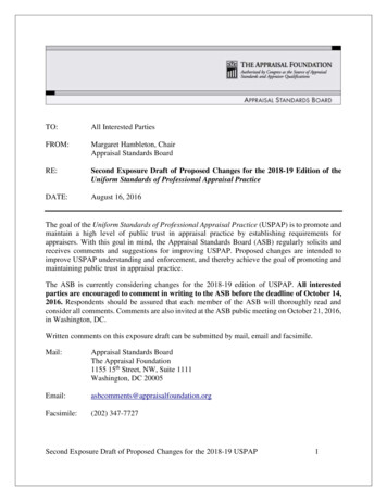
The Problem digital-flatpanel-x-ray-detector 28.jpg Many of our AEC systems have been calibrated for usewith screenscreen-film systemsThe energy response of gadolinium oxysulfide(Gd2O2S) screens is substantially different from that ofimage receptors used in digital radiographyThus, to properly expose digital radiographs, we mustrecalculate the kVp correction curve for our AECsystems to respond correctly considering the imagereceptor characteristicsThe Solution1.00E 04CsIGd2O2SBaFBrI Absorption cross section (cm2/g)1.00E 03BeamBeam-quality dependent calibration curves forAEC systems used for digital radiography1.00E 021.00E 011.00E 001.00E-01020406080100120140160Photon energy (keV)kVp Tracking Unit #18001207001006008050040060300Noise/SNR Doyle and Martin havecalculated theoreticalkVp correction curvesfor both CR and IDRdetectorsAlso note that theaddition of smallamounts of Cu filtrationdoes not significantlyaffect the calibrationPixel value Pixel yle, P and Martin, CJ, Calibrating automatic exposure controldevices for digital radiography, Phys. Med. Biol. 51:5475-5485, 2006.8
Thickness trackingPatient thickness 0069.0SNR92.0068.0Pixel value91.00 6789But, what about realisticpatient scatter scatter Scatter and AEC calibration Introduction of scatter is adifferent situation5Simple, uniformphantoms are desired forAEC testingAlso, consultingphysicists probably don’don’twant to lug around 65lbs. of PMMA – andengineers certainly won’won’teither So did 0.2 mm of Cu, butfluence was too high to achievereasonable exposure times. 2mm of Cu significantly alteredthe transmitted spectrum4What about phantoms?Further tightening kVp correction curveCalibrating with and using thin metal filtersMoral of the story: PMMA,water, and aluminum, in theappropriate amounts, deliversimilar transmitted spectra tothe AEC system and digitalreceptor3Patient thickness tracking not only adjusts exposure time butalso involves beam quality dependencies of detector absorptionefficiencies and AEC sensitivity as well as scatter absorption bythe AEC system and the contrast improvement factor of thegrid.130Phantoms for AEC calibration 2PMMA (in.)The overall variation I have seen when kVp trackingand thickness tracking are combined is 25-30% for onevendor (60 kVp) and 15% for another vendorWhen considering the combined impact of kVp andthickness variation, there is likely to be less variation fordigital radiography systems (SNR) than in S/F (O.D.)due to the fact that the variation in Bucky factor over arange of kVp’s no longer matters.Methods to attempt to improve on patient thicknesstracking might include 66.01Thickness tracking 67.090.00kVp 75.0Unit 298.0005076.0Unit 199.00SNR Unit 2215100.00SNR Unit 1225Noise/SNRPixel valuekVp Tracking - Unit #2Scatter does influenceabsolute calibration ofAEC sensitivity,however, but does nothave a large impact onthe kVp correction curveMany manufacturers doadjust the sensitivity ofthe AEC system basedon the presence/absenceof the antianti-scatter gridDoyle, P and Martin, CJ, Calibrating automatic exposure control devicesfor digital radiography, Phys. Med. Biol. 51:5475-5485, 2006.9
Future of Automatic ExposureControl in Radiography Fluoroscopy/angiography has already altered the wayADRC is performed These methods with TFT arrays do not work inradiography Fischer stereo unit – CCD array (Tony Siebert)CMOS (Tony Siebert) Thevenin B, Glasser F,Martin JJ-L, “Method anddevice for the taking ofdigital images with controland optimization of theexposure time of the objectto X or g radiation.”radiation.” CCD array with two ‘classes’classes’of pixelsIntegrator/comparatorImage corrected laterMonitoring signal value in a region of pixelsDetector is read many times per second US Patent 5937027Detector readout is destructivePixel architecture, with multiple transistors, allows forsampling without destroying the contained information Sobol WOther resources Goldman LW, Yester MV, Specifications,Performance Evaluations, and QualityAssurance of Radiographic and FluoroscopicSystems in the Digital Era, 2004 Summer SchoolProceedingsSobol WT, Advances in and specifications for radiographicX-ray systems, pg. 11-68 Goldman LW, Speed values, AEC performance evaluation,and quality control with digital receptors, pg. 271271-297 10
Measure SNR in a uniform portion of the image COVSNRSNR 0.05 Also, it is very important to find the minimum response time (MRT) of your AEC/generator and ensure that yourAEC/generator and ensure that your AEC exposure times do not fal AEC exposure times do not fall below this time AEC sensitivity Typically referenced to the center cell