Transcription
Gate ValveMaintenance& AdjustmentProcedures1Nor-Cal Products, Inc., 1967 South Oregon St., Yreka, CA 96097 Toll Free 800-824-4166 or 530-842-4457 www.n-c.comRev. 1-2013
Table of ContentsI.GATE AND BONNET O-RING 1.5” - 21” GATE VALVES.3II.BELLOWS, PNEUMATIC STANDARD 1.5” - 21” GATE VALVES.5III.ACTUATOR O-RING 1.5” - 21” GATE VALVES.8IV.SEAL PLATE ASSEMBLY/ PINS BEARING 1.5” - 21” GATE VALVES.10Vl.VALVE ADJUSTMENT 1.5” - 21” GATE VALVES.14VlI.VALVE ADJUSTMENT CHART 1.5” - 21” GATE VALVES.15Figures, Tables and DrawingsFigure 1BONNET ACTUATOR CARRIAGE ASSEMBLY. SEPARATED FROM VALVE BODY. 3Figure 2GATE O-RING AND BONNET PLATE O-RING. 4Figure 3BELLOWS AND PISTON SHOWN WITH ACTUATOR HOUSING REMOVED.5Figure 4PISTON CLOSE-UP FOR SPANNER WRENCH POSITIONING.5Figure 5BELLOWS AND ACTUATOR ASSEMBLIES DRAWING.7Figure 6DRIVE SHAFT O-RING.8Figure 7ACTUATOR O-RING.9Figure 8LINKAGE REMOVAL.10Figure 9PIN AND LINKAGE CLOSE-UP.11Figure 10GATE AND STRONG-BACK ASSEMBLIES OPENED.11Figure 11PIN, WASHERS AND R-RING REMOVAL DRAWING.12Figure 12GATE AND STRONGBACK ASSEMBLIES AFTER REASSEMBLY.13Figure 13STRONGBACK AND GATE ASSEMBLIES DRAWING.13Figure 14VALVE ADJUSTMENT TABLE.15Figure 15DIMENSIONS.15Figure 16PNEUMATIC ACTUATOR ASSEMBLY.162Nor-Cal Products, Inc., 1967 South Oregon St., Yreka, CA 96097 Toll Free 800-824-4166 or 530-842-4457 www.n-c.comRev. 1-2013
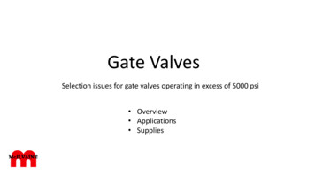
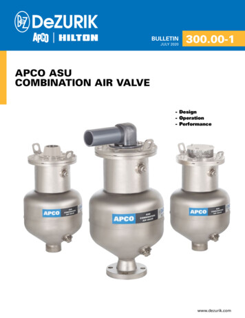
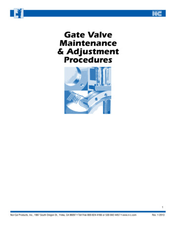
I. Viton Gate & Bonnet O-ringSTD AND MSB 1.5” - 21” GATE VALVESA. Tools and Materials Required:1. Allen Wrench for 1.5”—14” Gate Valves2.1/2” Box Wrench for 16”—21” Gate Valves3.O-Ring Pick4.Rubber Gloves5.Grease – Apezion L O-Ring Type6.IPAB. Procedure: Always wear Rubber Gloves when handling the Gate Valve1.Vent station and pump corresponding to Gate Valve to atmosphere.2.Actuate valve to Gate Open position.3.For safety, remove air to actuator.4.Remove bolts that hold Bonnet Actuator Assembly to body,or for Quick-Clamp Bonnet, undo the clamp.5.Pull out the Bonnet Actuator Carriage Assembly,taking care not to move adjustment of linkage.(Continued Next Page)VALVE BODYGATE ASSEMBLY &STRONGBACKLOWER AND UPPER LINKAGEBONNET PLATE ASSEMBLYACTUATOR ASSEMBLYACTUATOR TOP WITH SENSORS(OPENCLOSED)Figure 1 - BONNET ACTUATOR CARRIAGE ASSEMBLYSEPARATED FROM VALVE BODY3Nor-Cal Products, Inc., 1967 South Oregon St., Yreka, CA 96097 Toll Free 800-824-4166 or 530-842-4457 www.n-c.comRev. 1-2013
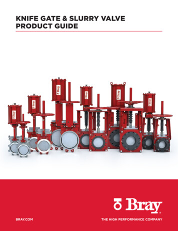
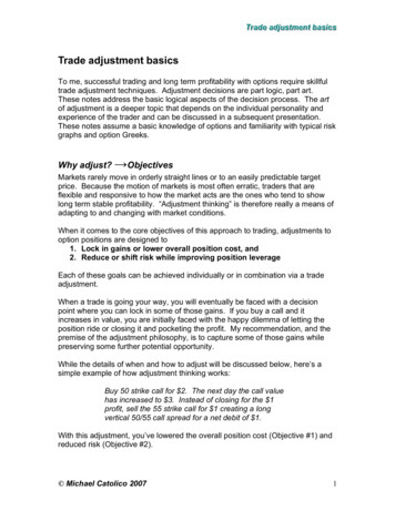
6.7.8.9.10.Remove O-Ring or Gasket from Bonnet Assembly and discard.Remove Gate O-Ring with the plastic pick, taking care not to scratch the O-Ring groove.Discard the O-Ring.Clean O-Ring groove with IPA and dry out with Nitrogen or CDA.Apply a light coat of Apezion L grease to the new Gate O-Ring. (It is very importantthat gloves are worn for this step)Install new O-Ring on gate, taking care to avoid twisting or deforming the O-Ring.11.Apply a light coat of Apezion L grease to the new Bonnet assembly Viton O-Ring/Copper Gasket. Install dry.12.Install new O-Ring/Gasket on Bonnet assembly, taking care to avoid twistingor deforming the O-Ring.13.Replace Bonnet Actuator Assembly into valve body.14.Install bolts and tighten. (For MSB, Copper gasket type, tighten side to side 20-25 ft-lb)BONNET PLATE O-RINGGATE ASSEMBLY O-RINGFigure 2: GATE O-RING AND BONNET PLATE O-RINGNOTE:1. BE CAREFUL NOT TOSCRATCH O-RINGGROOVE2. APPLY ONLY THINLAYER OF GREASE3. AVOID TWISTING,STRETCHING ORDEFORMING THEO-RING4Nor-Cal Products, Inc., 1967 South Oregon St., Yreka, CA 96097 Toll Free 800-824-4166 or 530-842-4457 www.n-c.comRev. 1-2013
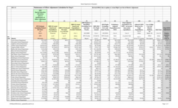
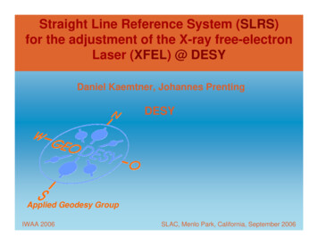
II. Bellows, Pneumatic Standard Cycle Only1.5” – 21” GATE VALVESA. Tools and Materials Required:1. Spanner Wrench2. Allen Wrench Set3. O-Ring Pick4. Pick (for R-Ring removal)5. Needle-Nose Pliers6. Small Standard Screw Driver7. Actuator O-Rings8. Grease for Bellows O-Ring: Apezion L9. Vacuum Grease10. IPA11. Heat Gun12. Lock-TiteB. Procedure:1. Vent station and pump corresponding to Gate Valve to atmosphere.2. Actuate valve to Gate Open position.3. For safety, remove air to actuator.4. Remove Actuator Cover. ( 2 screws)5. Remove Actuator Top. (6 screws)6. Measure the distance between the top of the Piston and the top of the Drive Shaft.(This will be helpful later during reassembly and adjustment)7. Remove the Jam Nut from the Drive Shaft. (Heat gun may be needed to melt theLock-Tite on the thread)(Continued Next Page)Figure 3: BELLOWS AND PISTONSHOWN WITHACTUATOR HOUSINGREMOVEDBELLOWSPISTONDIMENSION “A”5Nor-Cal Products, Inc., 1967 South Oregon St., Yreka, CA 96097 Toll Free 800-824-4166 or 530-842-4457 www.n-c.comRev. 1-2013
INDENTATIONS ON THEPISTON FOR SPANNER WRENCHNOTE: GATE MUST BE IN OPENPOSITION TO ACCESS THESE EASILYJAM NUTNOTE: May require use of theheat gun to melt any LOCK-TITEFigure 4 - PISTON CLOSE-UP FOR SPANNER WRENCH POSITIONING8.9.10.11.12.Using a spanner wrench, turn Piston counterclockwise to remove from Actuator Housing.Remove O-Ring from top of Drive Shaft.Remove remaining screws holding the Actuator Housing to the Bonnet Plate. (2 screws)Remove the Actuator Housing.Remove R-Ring from Drive Shaft, using a pick. If a replacement is NOT available, use care to preserve theR-Ring. Otherwise, pull out using the needle nose pliers and discard.13. Remove bellows by pulling and twisting slightly. Discard.14. Remove O-Ring in the Bellows drive shaft area and discard.15. Clean Drive Shaft groove and Bellows area with IPA.16. Apply a thin coat of grease (Apezion L) on the O-Ring for the Drive Shaft in Bellows area.17. Install O-Ring.18. Apply a thin coat of grease (Apezion L) on the O-Ring for the Bellows base Flange.19. Install O-Ring.20. Replace Bellows assembly on the Drive Shaft, pushing and twisting slightly to go over the O-Ring.21. Install R-Ring on the Drive Shaft, using a screw driver and a pick. Make sure it clicks into the groove next tothe top of the Bellows.22. Apply a thin coat of Vacuum Grease to the Drive Shaft.23. Install Actuator Housing on the Bonnet plate.24. Apply a thin coating of Vacuum Grease to the O-Ring for the top of the Drive Shaft.25. Install O-Ring on the top of the Drive Shaft.26. Apply a thin coating of vacuum grease to the Piston area, if necessary.(Continued Next Page)6Nor-Cal Products, Inc., 1967 South Oregon St., Yreka, CA 96097 Toll Free 800-824-4166 or 530-842-4457 www.n-c.comRev. 1-2013
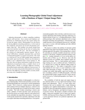
27. Install Piston on Drive Shaft; using a spanner wrench, turn clockwiseuntil the measurement in step # 5 is achieved.28. Install Jam Nut, using Lock-Tite and tighten.29. Install Actuator Top and tighten screws.30. Install Actuator Cover and tighten screws.31. Install air line and test operation of Valve and Actuator.Figure 5: BELLOWSAND ACTUATOR ASSEMBLIESDRAWINGSCREW (6X)ACTUATOR TOPO-RINGJAM NUTO-RINGPISTONMAGNETO-RINGACTUATOR HOUSEO-RINGR-RINGBELLOWS - BELLOWSEND FLG0-RINGR-RINGREED SW DRIVE SHAFTWASHER (3X)BEARINGR-RINGPINS (2X)STEMO-RING7Nor-Cal Products, Inc., 1967 South Oregon St., Yreka, CA 96097 Toll Free 800-824-4166 or 530-842-4457 www.n-c.comRev. 1-2013
III. Actuator O-ring1.5” – 21” GATE VALVES STD AND MSBA. Tools and Materials Required:1. Spanner Wrench2. Allen Wrench Set3. O-Ring Pick4. Pick (for R-Ring removal)5. Needle-Nose Pliers6. Small Standard Screw Driver7. Actuator O-Rings8. Grease for Bellows O-Ring: Apezion L9. Vacuum Grease10. IPA11. Heat Gun12. Lock-TiteB. Procedure:1. Actuate valve to Gate Open position.2. For safety, remove air to actuator.3. Remove Actuator Cover. (2 screws)4. Remove Actuator Top. (6 screws)5. Measure the distance between the top of the Piston and the top of the Drive Shaft.(This will be helpful later during reassembly and adjustment)6. Remove the Jam Nut from the Drive Shaft. (Heat gun may be needed to melt the Lock-Tite on the thread)7. Using a spanner wrench, turn Piston counterclockwise to remove from Actuator Housing.8. Remove O-Ring from top of Drive Shaft.(Continued Next Page)DRIVE SHAFT O-RINGNOTE: REMOVE THISO-RING FIRST BEFOREREMOVING THEACTUATOR HOUSINGFIGURE 6: DRIVE SHAFT O-RINGNor-Cal Products, Inc., 1967 South Oregon St., Yreka, CA 96097 Toll Free 800-824-4166 or 530-842-4457 www.n-c.com8Rev. 1-2013
9.Remove remaining screws holding the Actuator Housing to the Bonnet Plate. (2 screws)10. Remove the Actuator Housing.11. Remove O-Ring in Actuator Housing, using a pick and using care to not scratch the groove surface.ACTUATOR O-RINGNOTE:1. REMOVE THIS O-RINGBEFORE REMOVINGTHE ACTUATOR HOUSINGFigure 3: ACTUATOR O-RING2. BE CAREFUL NOT TOSCRATCH THE O-RINGGROOVE12. Apply a thin coat of vacuum grease on the new O-Ring.13 Install O-Ring.14. Inspect the drive shaft; clean and lubricate as necessary.15. Install Actuator Housing on the Bonnet plate. Tighten screws.16. Apply a thin coat of Vacuum grease on the O-Ring for the top of the Drive Shaft.17. Install O-Ring.18. Inspect actuator housing. Clean and lubricate as necessary.19. Apply a thin coat of vacuum grease on the O-Ring for the Piston.20. Install O-Ring on the Piston.21. Install Piston on Drive Shaft, using a spanner wrench and turning clockwise untilthe measurement in step # 5 is achieved.22. Install Jam Nut, using Lock-Tite and tighten.23. Apply a thin coat of vacuum grease to the O-Ring for the Actuator Top.24. Install O-Ring on the Actuator Top.25. Install Actuator Top and tighten screws.26. Install Actuator Cover and tighten screws.27. Install air line and test operation of Valve and Actuator.9Nor-Cal Products, Inc., 1967 South Oregon St., Yreka, CA 96097 Toll Free 800-824-4166 or 530-842-4457 www.n-c.comRev. 1-2013
IV. Seal Plate Assembly / Pins Bearing1.5”—21”A. Tools and Materials Required:1. Allen Wrench Set2. Arbor Press3. Punch4. Hammer5. Wrenches (Box or Open)6. R-R Pliers7. Vacuum Grease8. IPA9. Latex GlovesB. Procedure 4” – 21”1. Actuate valve to gate Open position.2. For safety, remove air to actuator.3. Remove bolts that hold Bonnet Actuator Assembly to body. For Quick-ClampBonnet, undo the clamp.4. Pull out the Bonnet Actuator Carriage Assembly.5. Using a punch and hammer, remove the pin that holds the Upper Linkage to theLower Linkage-Upper Linkage of Strongback. (Three washers and an R-Ring should be recovered)Note: If the pin does not move, flip the assembly over and try from the other side.Caution: Be careful not to bend the Upper Linkage; the use of a woodenblock for support is recommended)(Continued Next Page)HAMMERWOODEN BLOCKPUNCHLOWER LINKAGEUPPER LINKAGELOWER LINKAGE - STRONGBACKFIGURE 8: LINKAGE REMOVAL10Nor-Cal Products, Inc., 1967 South Oregon St., Yreka, CA 96097 Toll Free 800-824-4166 or 530-842-4457 www.n-c.comRev. 1-2013
6.7.Separate the Bonnet Upper Linkage Assembly from the Carriage Assembly.Measure the distance between the Strongback Lower Linkage and the Upper.Linkage-Lower Linkage. (This will be helpful later during reassembly and valve adjustment)Figure 5: PIN AND LINKAGE CLOSE-UPPIN (HOLDS UPPERAND LOWER LINKAGESDIMENSION “C”NOTE: IF PINDOESN’T COME OUTEASILY, FLIP OVERAND HIT WITHPUNCH ON THEOTHER SIDE8.Move Carriage assembly to a suitable work place for disassembly and the replacementof Pins, Bearings and R-Rings9. Remove Gate Spring by removing one set screw (Allen Wrench)10. Remove four set screws( Allen-3/32”) that hold Gate and Strongback together11. Separate Gate from Strongback.12. Remove Set Screws, Links, Washers, Pins, and Carriage Bars; Discard WashersFigure 6: GATE AND STRONGBACK ASSEMBLIES OPENEDWHEELLINKLOWER LINKAGE-STRONGBACKCARRIAGE BARGATE SPRING11Nor-Cal Products, Inc., 1967 South Oregon St., Yreka, CA 96097 Toll Free 800-824-4166 or 530-842-4457 www.n-c.comRev. 1-2013
13. Using a punch and hammer, remove wheels from their pin.Note: If the pin does not move, try from the other side.14. Using an arbor press, remove the bearings from the links and wheels; Discard expendable parts;15. Clean all reusable parts such as the gate, Strongback, Links, Carriage Bars, and Gate Spring with IPA;16. Press new Bearings in using an arbor press; For Viton Bonnet sealing valves, ensure that the Bear
Vent station and pump corresponding to Gate Valve to atmosphere. 2. Actuate valve to Gate Open position. 3. For safety, remove air to actuator. 4. Remove bolts that hold Bonnet Actuator Assembly to body, or for Quick-Clamp Bonnet, undo the clamp. 5. Pull out the Bonnet Actuator Carriage Assembly, taking care not to move adjustment of linkage. (Continued Next Page) VALVE BODY GATE