Transcription
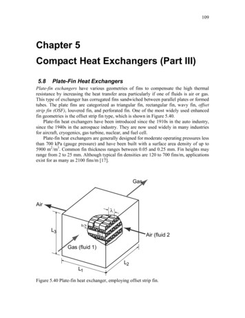
20Fouling in Plate Heat Exchangers:Some Practical ExperienceAli Bani Kananeh and Julian PeschelGEA PHE SystemsGermany1. IntroductionDue to their compact size, Plate Heat Exchangers (PHEs) are widely used in industrialprocesses. They have higher heat-transfer performance, lower temperature gradient, higherturbulence, and easier maintenance in comparison with shell and tube heat exchangers. Forminimizing material consumption and space requirements compact models have beendeveloped over the last years. By using thin plates forming a small gap, these compactmodels impress with larger heat transfer coefficients and, thus, smaller required heattransfer area.The advantages of compact heat exchangers over shell and tube ones at a glance: larger heat transfer coefficientssmaller heat transfer surfaces requiredlower fouling due to high fluid turbulences (self-cleaning effect)significantly smaller required installation and maintenance spacelighter weightsimplified cleanability especially for GPHElower investment costscloser temperature approachpure counter-flow operation for GPHEIn Figure 1, plate heat exchangers are compared with shell and tube heat exchangersregarding effectiveness, space, weight and cleaning time.Deposits create an insulating layer over the surface of the heat exchanger that decreases theheat transfer between fluids and increases the pressure drop. The pressure drop increases asa result of the narrowing of the flow area, which increases the gap velocity (Wang et al.,2009). Therefore, the thermal performance of the heat exchanger decreases with time,resulting in an undersized heat exchanger and causing the process efficiency to be reduced.Heat exchangers are often oversized by 70 to 80%, of which 30 to 50% is assigned to fouling.While the addition of excess surface to the heat exchanger may extend the operation time ofthe unit, it can cause fouling as a result of the over-performance caused by excess heattransfer area; because the process stream temperature change greater than desired, requiringthat the flow rate of the utility stream be reduced (Müller-Steinhagen, 1999). The depositswww.intechopen.com
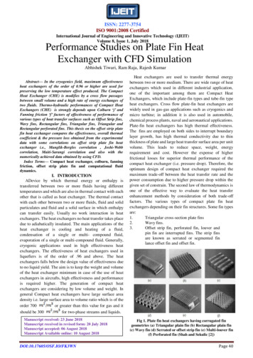
534Heat Exchangers – Basics Design ApplicationsFig. 1. Comparison of plate heat exchanger with shell and tube heat exchanger.must be removed by regular and intensive cleaning procedures in order to maintainproduction efficiency.As a result of the effects of fouling on the thermal and hydraulic performance of the heatexchanger, an additional cost is added to the industrial processes. Energy losses, lostproductivity, manpower and cleaning expenses cause immense costs. The annual cost ofdealing with fouling in the USA has been estimated at over 4 billion (Wang et al., 2009).The manner in which fouling and fouling factors apply to plate exchangers is different fromtubular heat exchangers. There is a high degree of turbulence in plate heat exchanger, whichincreases the rate of deposit removal and, in effect, makes the plate heat exchanger lessprone to fouling. In addition, there is a more uniform velocity profile in a plate heatexchanger than in most shell and tube heat exchanger designs, eliminating zones of lowvelocity which are particularly prone to fouling. Figure 2 shows the fouling resistances forcooling water inside a plate heat exchanger in comparison with fouling resistances on thetube-side inside a shell and tube heat exchanger for the same velocity. A dramaticdifference in the fouling resistances can be seen. The fouling resistances inside the PHE aremuch lower than that inside the shell and tube heat exchanger.Fouling inside heat exchanger can be reduced by: Appropriate heat-exchanger designProper selection of heat-exchanger typeMitigation methods (mechanical and/or chemical)Heat exchanger surface modification/coatingThe mechanics of deposits build-up and the impact of operating conditions on thedeposition rate should be understood in order to select the appropriate method to reducefouling (Müller-Steinhagen, 1999).www.intechopen.com
Fouling in Plate Heat Exchangers: Some Practical Experience535Fig. 2. Comparison of fouling resistance in PHE to tube-side fouling resistance (MüllerSteinhagen, 2006).This chapter focuses on solving fouling problems in some industrial applications. The firstsection presents fouling problems with cooling water inside CO2 coolers in differentEgyptian fertilizer plants. The effect of heat exchanger geometry and flow patterns on thefouling behavior will be shown. Thermodynamic and hydraulic solutions are proposed like,redesigning of the plate heat exchangers and new plate geometries. The second sectionexplains how fouling can be reduced inside gasketed plate heat exchangers used in foodproduction using Nano-composite coatings. An antifouling coating with low surface energy(low wettability) can be used to avoid or minimize adhesion, improve process management,simplify cleaning processes with less resources and chemical use, and increase productreliability. The operational efficiency of the plant can be significantly improved and theintensity and frequency of cleaning can be substantially reduced.2. Solving fouling problems by heat exchanger design modificationFouling problems with cooling water inside CO2 coolers in different Egyptian fertilizerplants were investigated. Thermodynamic and hydraulic solutions were proposed, whichincluded redesign of the existing PHEs and new plate geometries. The main problems arosefrom the large surface margins required to meet pressure drop limits on the CO2 side.Reducing the surface area of the heat exchanger increased the fluid velocity (shear stressfrom 5.31 to 10.84 Pa) inside the gaps and hence decreased fouling. Using computer-www.intechopen.com
536Heat Exchangers – Basics Design Applicationsmodeled plate geometries from the new technology (NT) series with larger gap velocitiesdue to better fluid distribution over the plates could decrease fouling and increase theavailability of fertilizer plants.2.1 IntroductionTo guarantee production reliability in the complex urea fertilizer manufacturing process,PHEs are installed in several process chains including CO2 cooling, residual gas scrubbing,and other process sections as were as in the primary urea production plant. Industrialprocesses commonly use water for cooling purposes. Open circuit cooling system is used insome processes, while closed loop system involving cooling towers is used in others. Closedloop systems usually cause less fouling than open ones, but they are more expensive(Kukulka and Leising, 2009). Cooling water normally contains dissolved or suspendedsolids like calcium carbonate and calcium sulphate. If the concentration of these dissolvedsolids exceeds certain limits, it leads to the accumulation of deposits on the heat exchangersurface (Müller-Steinhagen, 1999). These deposits create an insulating layer on the surface ofthe heat exchanger that decreases the heat transfer between the two fluids. The thermalperformance of the unit decreases with time as the thickness of the deposit increases,resulting in an undersized heat exchanger and causing the process efficiency to be reduced(Kukulka and Leising, 2009). Deposit formation can be reduced either by changing theconfiguration of the heat exchanger or by regular cleaning procedures.Deposit formation is influenced by the heat exchanger surface and geometry, coolingmedium and the operating conditions. Its composition depends on the flow rate,temperature and chemical composition of the cooling medium (Kukulka and Leising, 2009).Pana-Suppamassadu et al. (2009) studied the effect of plate geometry (contact angle) and thegap velocity on calcium carbonate fouling in plate heat exchanger. They found that anincrease in the gap velocity could reduce the fouling rate on the surface of plate heatexchanger.In the present section, deposit formation on the surface of plate heat exchangers in differentEgyptian fertilizer plants will be investigated. The effect of heat exchanger geometry andflow patterns on the fouling behavior will be shown.2.2 Process descriptionAmmonia is the basic raw material in urea production. Ammonia plants in question operateusing Uhde's proprietary ammonia process that is based on the well-established HaberBosch process. In the first stage, the raw material natural gas is desulphurized, then crackedinto its individual chemical components catalytically by adding steam to generate thehydrogen required for ammonia synthesis. This process also generates carbon monoxide,carbon dioxide, hydrogen and residues of methane from the natural gas cracking process. Inthe next stage nitrogen is added to the process by combusting methane, CO and H2 usingair. With the addition of steam, carbon monoxide is converted to CO2 using catalyticconverters and then scrubbed out of the synthesis gas formed. The selectively scrubbed CO2is fed into the urea processing plant as the process medium together with the producedammonia as starting material. The urea plants operate using the Stamicarbon process thatwas developed in the Netherlands [Uhde].www.intechopen.com
Fouling in Plate Heat Exchangers: Some Practical Experience537Fig. 3. Ammonia process [Uhde].In the CO2 scrubbing process three plate heat exchangers are switched in parallel, two inoperation (A and B) and one in standby (C). Figure 4 shows the three coolers with theiroperating conditions. The CO2 flows into the PHEs as a gas-steam mixture at 94 C and iscooled down in a countercurrent process to 33 C. Water at 30 C is used as coolant. Each ofthe 10 tons and 3 meter high PHEs has 1000 m² of high-performance stainless steel (1.4539;AISI 904 L) VT-plates. The transferred heat capacity is 14.5 megawatts.Fig. 4. CO2 coolers used in the scrubbing process.www.intechopen.com
538Heat Exchangers – Basics Design ApplicationsNile river water treated by NALCO inhibitors is used in an open loop as the coolingmedium for the CO2 coolers, the specifications of the cooling water used is given in Table 1.Nile waterCaHAlkalinityChlorides90 ppm13825 ppmInhibitorsN-7356P: 30ppm,N-73203: 95ppmTable 1. Cooling water specifications.A typical analysis for Nile river water is shown in Table 2.SubstrateChlorideCaMgNaKFeSO4SiO2HCO3KMnO4Total pm CaCO3ppmppm CaCO3Table 2. Nile river water analysis.2.3 Problem description and observationsThe cooling water flow rate on the CO2 coolers (HP Scrubber) dropped from 500m³/hr to300m³/hr due to fouling on the cooling water side, which caused operation problems in theUrea plant. The CO2 outlet temperature was increasing with time and achieved about 50 Cafter 30 days of operation before the shutdown of the unit for mechanical cleaning. The CO2cooler was opened for mechanical cleaning; the PHE’s inlet was plugged with plastic bagsand pieces of bottles. Deposits were accumulated at an area about 20cm from the plate inletand selectively covered the plate surface, as can be seen in Figure 5. They could plug thechannels and restrict the water flow over the plate. These deposits accumulated due to thereduction of the gap velocity (shear stress) which increased the surface temperature.A sample from the deposits was taken and analysed using ashing and X-ray Fluorescence(XRF). The sample was dried at 105 C before ashing and XRF analysis. The results areshown in Table 3.The ashing results showed that 14% of the sample was lost at a temperature below 500 C,which represents the organic material and can be considered as normal range. The XRFanalysis showed that the main element in the deposits is zinc hydroxide as ZnO (38%) andwww.intechopen.com
539Fouling in Plate Heat Exchangers: Some Practical ExperienceFig. 5. Deposits formed on the surface of VT-plate.the second is calcium phosphate (11%), which participated as a result of the increase of theplate surface temperature resulting from the reduction in the cooling water flow rate.Loss at 500 CLoss at 925 C14 %23 %(a)SubstrateMagnesium (MgO)Aluminium (Al2O3)Silicon (SiO2)Phosphorous (P2O5)Sulphur (SO3)Calcium (CaO)Iron (Fe2O3)Zinc (ZnO)Total oxides (normalized to loss 925 C)(b)Mass %3122011113877Table 3. (a) Ashing results, (b) Elemental analysis as oxides using XRF.2.4 Technical solutions2.4.1 Redesigning of the PHEsThe surface area of the CO2 cooler was reduced by removing 86 plates out of 254 plates (thesurface area was reduced by 34%). The average cooling water velocity inside the gaps wasincreased from 0.30 to 0.42 m/s, as can be seen in Table 4.www.intechopen.com
540Heat Exchangers – Basics Design ApplicationsPlates numberGap velocity [m/s]Surface tension [Pa]Reynolds numberSurface temperature [ C]Original Design2540.305.31325972After modification1680.4210.84459969Table 4. Design modification for CO2 cooler in Helwan fertilizer plant, Egypt.The deposits formed on the surface of the plates were decreased as a result of the increase inthe shear stress and the decrease of the surface temperature from 72 to 69 C. The surfacetemperature was calculated from the fluids temperatures, thermal conductivities and dutieson both sides. The operation time for the cooler was increased from 30 days to 43 days andthe plates were cleaned after more than 40 days of operation, as shown in Figure 6.The CO2 outlet temperature started to increase after about 23 days of operation due to theaccumulation of deposits on the cooling water side which led to a reduction in the coolingwater flow rate. The unit was opened after about 43 days for mechanical cleaning.Fig. 6. Inlet and outlet CO2 temperatures as a function of time.2.4.2 New plate geometryA new cooler with computer-modeled plate geometry from the NT (New Technology) serieswas installed in parallel with the existing two coolers. The NT Series sets new economicwww.intechopen.com
Fouling in Plate Heat Exchangers: Some Practical Experience541standards with low investment costs, operation and maintenance. The optimized OptiWaveplate design requires less heat transfer surface for the same performance. The new EcoLocgaskets and installation methods simplify maintenance and ensure a perfect fit of the gasketand plate packs. The new plates have the advantage of higher gap velocities (shear stress)due to better fluid distribution over the plates and smaller gap size.The advantages of the NT-plates at a glance: High heat transfer ratesLow investment and service costsOptimized distribution of mediaSimplified handlingQuick and safe gasket replacementFlexible solutions for special requirementsNon-standard materials availableLeading manufacturer’s know-howIn conventional plates the fluid velocity over the plate’s width is decreasing, the more thefluid is distributed from the inlet over the whole plate width. This is due to the higherpressure drop in longer flow channels. The optimized fluid distribution channels of the NTseries lead to balanced velocity over the whole plate width and an equal distribution of themedium (Figure 7).The flow channels of the NT-plates vary in their width and were optimized based onComputational Fluid Dynamics (CFD). The channels located further away from the inlethole have bigger diameter than those closer to the inlet hole.Fewer deposits were accumulated on the NT-plates due to the asymmetric flow distributionover the channels as can be seen in Figure 8. These deposits were formed because the unitwas taken into operation in parallel with the old two VT-plates units and hence most of thecooling water was flowing inside them. The NT-plates unit was designed in principle toreplace one of the VT-plates units so that the gap velocity could be increased.Fig. 7. Velocity distribution over the NT-plate compared with conventional plates.www.intechopen.com
542Heat Exchangers – Basics Design ApplicationsFig. 8. Deposits formed on the surface of NT-plate.2.5 ConclusionsNile water treated with NALCO inhibitors caused fouling problems inside CO2 coolers indifferent Egyptian ammonia plants. Technical solutions including redesigning of the PHEsand new plate geometries were investigated. Reducing the surface area of the CO2 coolersby 34% increased the gap velocity from 0.30 to 0.42 m/s (shear stress from 5.31 to 10.84 Pa)and hence decreased fouling. The operation time for the cooler was increased from 30 daysto 43 days. NT-plates with asymmetric flow distribution over the channels decreased therate of deposition on the surface of the plates.3. Solving fouling problems by surface modificationIn a recent study, Nano-composite coatings were used to reduce fouling inside gasketedplate heat exchangers involved in food production. An antifouling coating with low surfaceenergy (low wettability) led to a hydrophobic and oleophobic effect. The goal of the projectwas the application of new surface coatings (nanotechnology) to avoid or minimizeadhesion, improve process management, simplify cleaning processes with lesser resourcesand chemical use, and increase the product reliability.The test facility constructed by the Institute of Environmental Process Engineering (IUV) atthe University of Bremen in Germany used for the investigation of milk adhesion and thestability of the coatings on small cylindrical ducts. A number of coatings and surfacetreatments were tested. A pilot plant including a milk pasteurizer at the Institute of FoodQuality LUFA Nord-West in Oldenburg-Germany was used for the thermal treatment ofwhey protein solutions. Heat exchanger plates coated with different nano-composites aswell as electropolished plates installed in the heating section of the pasteurizer were tested.Significant differences were observed between coated and uncoated plates. The coatedplates showed reduced deposit buildup in comparison with the uncoated stainless steelplates. Polyurethane-coated plates exhibited the thinnest deposit layer. Electro-polishedwww.intechopen.com
Fouling in Plate Heat Exchangers: Some Practical Experience543plates also reduced deposit buildup in comparison to the standard stainless steel plates andwere almost comparable to the coated plates. The time required for cleaning in place (CIP)with the coated plates was reduced by 70% compared to standard stainless steel plates.3.1 IntroductionProduction problems, like decrease of production rate and increase in the intensity ofcleaning procedure, arise in the dairy industry as a result of the deposit adhesion to theplate surface. The deposits must be removed by regular and intensive cleaning proceduresin order to comply with hygiene and quality regulations for the dairy industry (Augustin etal., 2007). If not controlled carefully, deposits can cause deterioration in the product qualitybecause milk cannot be heated up to the required pasteurization temperature. Milk depositsgenerally form so fast that heat exchangers must be cleaned regularly to maintainproduction efficiency and meet strict hygiene standards and regulations (Bansal and Chen,2006). Energy losses, lost productivity, manpower and cleaning expenses cause immensecosts (Beuf et al., 2003). In the dairy industry, fouling and the resulting cleaning of theprocess equipment account for about 80% of the total production costs (Bansal and Chen,2006).Gasketed plate heat exchangers with stainless steel plates are commonly used in the dairyindustry. Stainless steel surfaces have high surface energies. The adhesion of product onsolid surfaces is determined by the surface roughness and surface energy. The adhesion ofdeposits could be reduced by either decreasing the surface energy of the metal or by coatingthe metal surface with high anti-adhesion effect (low surface energy) materials, such asthose made of nanoparticles (Gerwann et al., 2002). The application of nano-coatings withtheir anti-adhesion effects reduces the buildup of deposits on the surface of heat exchangerplates due to the reduction of adhesive forces. The operation efficiency of the plant can besignificantly improved and the general hygienic situation of the product can increase.Additionally, intensity and frequency of cleaning can be substantially reduced to achievethe desired degree of product quality (Kück et al., 2007).Beuf et al. (2003) studied the fouling of dairy product on modified stainless steel surfaces ina plate and frame heat exchanger. Different surface modifications, such as coatings(diamond like carbon [DLC], silica, SiOX, Ni-P-PTFE, Excalibur, Xylan) and ionimplantation (SiF , MoS2) were analyzed. No significant difference was found between themodified stainless steels and the unmodified one. The cleaning efficiency of plates coatedwith Ni-P-PTFE was the best. The experimental results of Zhao et al. (2007) showed that thesurface free energy of the Ni–P–PTFE coating had a significant influence on the adhesion ofbacterial, protein and mineral deposits. The Ni–P–PTFE coating reduced the adhesion ofthese deposits significantly.The fouling behavior of whey protein solutions on modified stainless steel (SS) surfacescoated with diamond-like carbon (DLC) and titanium nitride (TiN) have been studied byPremathilaka et al. (2007). They concluded that fouling decreased in the order DLC SS TiN and cleaning time decreased in the order TiN SS DLC.The goal of the present work is to assess new surface coatings (developed by the Institute ofNew Materials, INM, in Germany) with low surface energy and low roughness to avoid orminimize adhesion of deposits, simplify cleaning processes, reduce resource and chemicalwww.intechopen.com
544Heat Exchangers – Basics Design Applicationsrequirements, and increase product quality and consistency. The work will assess thedeposit buildup during the thermal treatment of milk.3.2 Experimental3.2.1 Coated surfacesThe anti-adhesion nano-composite coatings, with hydrophobic and oleophobic effectiveness,used in this work were produced from commercially available polymer matrices such asepoxy, polyurethane or Polyamide systems which were reactively cross-linked with perfluorinated monomers (or oligomers) and ceramic reinforcement particles. The coatingmaterial application was similar to wet chemical coating by spraying, and the requiredmechanical properties were obtained through a thermal cross linking step. The epoxy andpolyurethane systems were hardened at 130 C for 1 hour, while the Polyamide systemswere hardened at 200 C for 2 hours, in order to ensure an optimum layer formation. Table 5summarizes the plates used and their specifications.PlateMaterialU1Stainless steelElectrically-polished stainless steelfor one minuteElectrically-polished stainless steelfor five minutesEpoxy-resin based coating of INMEpoxy-resin based coating of INMPolyurethane based coating of INMPolyurethane based coating of INMEpoxy-resin based coating of INMU1min,eU5min,eA1A2A9A10A17Contact angleWater [ ]83.8Contact angleMilk [ ]69.6Surface 14Table 5. Contact angle and surface roughness of the sheets prepared by INM.3.2.2 Laboratory scale testingA laboratory facility was constructed by the Institute of Environmental Process Engineering(IUV), University of Bremen in Germany, for the investigation of milk adhesion. A heatexchanger was designed to enable thermal and hydraulic load measurements with variabledesigns. Its principal components were a double wall heated receiver tank, controllablepump, electromagnetic flow meter and the test cell (duct). A closed loop recirculationconfiguration was used to decrease the volume of the test medium required. Furthermore, afast sample change by simple removal of the test cell (duct) was performed. Figure 9 showsthe laboratory apparatus used and the test duct. The test channel employs an annulargeometry, where the inner cylinder is engaged with an electric heater. The middle part (withthe threaded ends) is made of stainless steel, while the coin section (right) and the fastener(left) are made from a high-performance plastic Polychlorotriflouroethylene (PCTFE). Thisarrangement allows the middle section, which incorporates the heater, to be heated bythermal conduction without large heat losses. The coating material is applied to a smallstainless steel tube which is pushed over the heater.www.intechopen.com
Fouling in Plate Heat Exchangers: Some Practical Experience545Fig. 9. Flowchart of laboratory heat exchanger apparatus (Institute of Environmental ProcessEngineering IUV, Universität Bremen).For the experiments, a 10% (by weight) aqueous whey protein solution was set in thereceiver tank. The solution was prepared by solving a whey protein concentrate WPC35 inwater until the required concentration was obtained. The pH was adjusted to 6.0 using a 0.1mol/liter HCl solution. Pre-heating was carried out to about 43 C. The solution waspumped in the closed cycle of the experimental setup, the electric heater of the test channelwas activated and the measuring procedure was started. After each trial, the whey proteinsolution was replaced to exclude any effect of heating on the ingredients. After each run, thetube was cleaned with 0.1 molar NaOH solution with cross flow velocity of 0.6 m/s. Theexperimental parameters were:Volumetric flow rate: 0.036 – 0.37 m3/hWhey protein concentration: 10% (by weight)Average flow velocity in annulus: 0.2 m/sFluid temperature (measuring section): 45 CTemperature of the heating element: 230 CHeat flux: 20 kW/m²Experimental time: 15 to 30 min.3.2.3 Pilot plant testingIndustrial tests with milk were carried out on a small plant by the Institute of Food QualityLUFA-Oldenburg-Germany, with the support of the company GEA PHE Systems (Figure10). The pilot plant can produce almost all dairy products. It is used for training purposes aswell as technological support and procedure development to the food industry.www.intechopen.com
546Heat Exchangers – Basics Design ApplicationsFig. 10. Pilot plant used for practical tests (Institute of Food Quality LUFA-OldenburgGermany) with GEA Ecoflex VT04 plate heat exchanger.The plate heat exchanger, in which coated and uncoated plates can be installed, consists oftwo cooling sections (deep cooler with 8 plates and pre-cooler with 10 plates), heat recoverysection (with 12 plates), heating section (with 7 plates) and hot water section (with 6 plates).Before assembling the heat exchanger, selected plates in the heating and heat recoverysections were coated using the method described in section 3.2.1. As a reference, stainlesssteel, electro-polished and PTFE coated plates were also installed in the heat exchanger(Figure 11). Table 6 details the samples used and their specifications.Fig. 11. Plates layout inside GEA Ecoflex VT04 plate heat exchanger.www.intechopen.com
547Fouling in Plate Heat Exchangers: Some Practical less steelElectrically-polished stainless steelEpoxy-resin based coating of INMPolyurethane based coating of INMPolyurethane based coating of INMPolyurethane based coating of INMTeflonThickness [ m]83.753.085.227.622.5Table 6. Samples specifications used in the pilot plant experiments by LUFA.The milk was pumped from the receiver tank through the pasteurizer at a constant flowrate. The process steps of heating, cooling and heat recovery were combined together. Aftera working time of 4 hours, the test was stopped and the plates of the heater and heatrecovery sections were removed in order to measure deposit formation. Visual observationsand mass investigations were done. Furthermore, the cleaning effectiveness was assessed.3.3 Results and discussionTechnical investigations were carried out by IUV and LUFA on the deposits formed fromwhey protein solution in both the laboratory facility and the pilot plant.3.3.1 Laboratory tests by IUVLaboratory investigations were carried out by IUV on the deposit of whey protein on thetube surface. Different stainless steel tubes were tested by IUV using the laboratory heatexchanger apparatus described in section 3.2. Figure 12 shows the deposit accumulationrates of whey protein solution for the different tube surfaces.Fig. 12. Deposit accumulation rates for laboratory tests with whey protein on small coatedcylindrical ducts. Plate characteristics are given in Table 6.www.intechopen.com
548Heat Exchangers – Basics Design ApplicationsThe Polyurethane-coated tubes gave the thinnest deposit layer, closely followed by theelectropolished tubes. The laboratory cleaning tests showed that under the samehydrodynamic conditions, the cleaning time for test tube A9 is only 20% of that needed forthe standard stainless steel tube.3.3.2 Pilot plant tests by LUFAIn a test series LUFA Nord-West in Oldenburg-Germany examined the formation of depositon test PHE plates which had undergone different treatments. Different coated plates wereinstalled in the heating section of a pasteurizer, with PTFE coated plates next to electropolished and standard stainless steel plates. The anti-fouling coatings were high-molecularpolymers with implanted nano-particles which resulted in high hardness and scratchresistance. The pasteurizer was operated with a 10% (by weight) whey protein solutionwhich was heated up to 85 C. Figure 13 shows the amount of residue, in g, for differentsurfaces in three tests. It is noteworthy that in these test conditions there is significant wheyprotein deposition on uncoated, electro-polished and A2-coated stainless steel.The coatings A2 and A10 showed reduced deposit buildup (the PTFE coating gave moredeposit buildup than the standard stainless steel plate). The plates coated with A10 coatinghad the lowest adhesion, which was similar to the laboratory test results. The depositbuildup on the electro-polished plates was lower than the standard stainless steel plate andalmost comparable to the coated plates. Cleaning studies indicated that the cleaning in place(C
Heat Exchangers Basics Design Applications 534 Fig. 1. Comparison of plate heat exchan ger with shell and tube heat exchanger. must be removed by regular and intensive cleaning procedures in order to maintain production efficiency. As a result of the effects of fouling on the thermal and hydraulic