Transcription
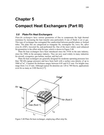
ISSN: 2277-3754ISO 9001:2008 CertifiedInternational Journal of Engineering and Innovative Technology (IJEIT)Volume 8, Issue 1, July 2018Performance Studies on Plate Fin HeatExchanger with CFD SimulationAbhishek Tiwari, Ram Raja, Rajesh KumarAbstract— In the cryogenics field, maximum effectivenessheat exchangers of the order of 0.96 or higher are used forpreserving the low temperature effect produced. The CompactHeat Exchanger (CHE) is modifies by a cross flow passagesbetween small volume and a high rate of energy exchanges oftwo fluids. Thermo-hydraulic performances of Compact HeatExchangers (CHE) is strongly depends upon Colburn ‘j’ andFanning friction ‘f’ factors of effectiveness of performance ofvarious types of heat transfer surfaces such as Offset Strip fins,Wavy fins, Rectangular fins, Triangular fins, Triangular andRectangular perforated fins. This thesis on the offset strip platefin heat exchanger compares the effectiveness, overall thermalcoefficient & the pressure loss obtained from the experimentaldata with some correlations on offset strip plate fin heatexchanger i.e., Manglik-Bergles correlation , Joshi-Webbcorrelation, Maiti-Sarangi correlation and also with thenumerically achieved data obtained by using CFD.Index Terms— Compact heat exchanger, colburn, fanningfriction, offset strip plate fin and computational fluiddynamics.I. INTRODUCTIONADevice by which thermal energy or enthalpy istransferred between two or more fluids having differenttemperatures and which are also in thermal contact with eachother that is called as heat exchanger. The thermal contactwith each other between two or more fluids, fluid and solidparticulates and fluid and a solid surface in which enthalpycan transfer easily. Usually no work interaction in heatexchangers. The heat exchangers no heat transfer takes placedue to adiabatically insulated. The main applications of theheat exchanger is cooling and heating of a fluid,condensation of a single or multi- compound fluid,evaporation of a single or multi-compound fluid. Generally,cryogenic applications used in high effectiveness heatexchangers. The effectiveness of heat exchangers used inliquefiers is of the order of .96 and above. The heatexchangers falls below the design value of effectiveness dueto no liquid yield. The aim is to keep the weight and volumeof the heat exchanger minimum in case of the use of heatexchangers in aircrafts, high effectiveness and performanceis required higher. The generation of compact heatexchangers are considering by low volume and weight. Ingeneral Compact heat exchangers have large surface areadensity i.e. large surface area to volume ratio which is of theorder 700/or greater than this value for gas and itshould be 300/for two-phase streams and liquids.Manuscript received: 23 June 2018Manuscript received in revised form: 20 July 2018Manuscript accepted: 06 August 2018Manuscript Available online: 10 August 2018DOI:10.17605/OSF.IO/FK3WNHeat exchangers are used to transfer thermal energybetween two or more medium. There are wide range of heatexchangers which used in different industrial application,one of the important among them are Compact HeatExchangers, which include plate-fin types and tube-fin typeheat exchangers. Cross flow plate-fin heat exchangers arewidely used in gas-gas applications such as cryogenics andmicro turbine; in addition it is also used in automobile,chemical process plants, naval and aeronautical applications.Plate-fin heat exchangers has high thermal effectiveness.The fins are employed on both sides to interrupt boundarylayer growth, has high thermal conductivity due to thinthickness of plate and large heat transfer surface area per unitvolume. This leads to reduce space, weight, energyrequirement and cost. However the expense of higherfrictional losses for superior thermal performance of thecompact heat exchanger (i.e. pressure drop). Therefore, theoptimum design of compact heat exchanger required themaximum trade-off between the heat transfer rate and thepower consumption due to higher pressure drop within thegiven set of constrain. The second law of thermodynamics isone of the effective way to evaluate the heat transferenhancement methods by consideration of both trade-offfactors. The various types of compact plate fin heatexchangers depending on their fin structures. Some fin typesare:1.Triangular cross-section plate fins2.Wavy fins.3.Offset strip fin, perforated fin, louver andpin fin are interrupted fins. The strip finsare known as serrated or segmented finlance offset fin and offset fin.Fig 1. Plate fin heat exchangers having corrugated fingeometries (a) Triangular plain fin (b) Rectangular plain fin(c) Wavy fin (d) Serrated or offset strip fin (e) Multi-louver fin(f) Perforated fin (Shah and Sekulic [2])Page 40
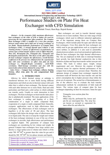
ISSN: 2277-3754ISO 9001:2008 CertifiedInternational Journal of Engineering and Innovative Technology (IJEIT)Volume 8, Issue 1, July 2018II. MEASUREMENT PRINCIPALESV. TRADE-OFF FACTORS AND SYSTEM BASEDOPTIMIZATIONThe heat transfer characteristics of the Plate fin heatInheatexchangerdesign, the process & problemexchanger experimented by Kays and London on along withthe pressure drop characteristics, in a most effective and specification is one of the most important steps. Anyreliable manner [1]. A cross-flow type heat exchanger specification for process and design procedure counts all theexperimental set-up dealted. But we did our set-up for offset required information for designing and optimizing thestrip fin type surface as counter flow type plate fin heat exchanger for a particular application. It includes: Specification of the problem for operatingexchanger [3]. Here the cool ambient air is drawn by theconditionscompressor through a channel and is being heated by using Type of heat exchangerheat exchanger and a heater where air is heated & these Type of flow arrangementheated air transfers heat to the cold air through the Materialsexchanger. The pressure gauges are used for measuring the Considerations for design/manufacturing/operationpressure at the inlets of the both the fluids. Similarly Information on the minimum input specificationsResistance Temperature Detectors (RTDs) are used forThe selection of design conditions is the first andmeasuring the temperature at the inlet and outlet of both theimportant consideration. Then, the next is the off-design andfluids. By measuring the temperature and mass flow rate,design point condition. The specification for operatingeffectiveness can be calculated. Overall thermal conductanceconditions and the operating environment should beand Number of Transfer units (NTU) can be determined frommentioned which includes:the measurement of effectiveness. Mass flow rates Fluid types and their thermos-physical propertiesIII. OBJECTIVE OF THE STUDY Inlet temperature & pressure of both fluid streams The offset strip plate fin heat exchanger rating and sizing,Maximum allowable pressure drop on both fluidwe have reviewed many correlations between the heatsides Inlet temperature & pressure fluctuation due totransfer factor in the literature coefficient and friction. Thevariation in the process or environmentalmain objective is the evaluation of the performanceparametersparameters of a counter flow heat exchanger. This is done by Corrosivenessfollowing steps: Fouling characteristic of fluids andi.Based on the chosen correlation, an offset strip plate Operating environmentfin heat exchanger have been designed.Theheatexchanger specification includes heat exchangerii.For a given design data, industrial fabrication of theincludesexchangerconstruction type, flow arrangement,plate fin heat exchanger is done.coregeometry,&fintype. For compact plate fin heatiii.Test fabrication for testing.exchangers,onecanchooseoffset strip fin, louver fin or otheriv.The effectiveness, heat transfer coefficient,fin geometry.pressure drop etc. are obtained for the experimentand these obtained values will be compared withthe rating values of the plate fin heat exchangerVI. NUMERICAL ANALYSIS BY CFDbased on various correlations and by CFD analysis.The computational fluid dynamics is used for theThe correlations used for Plate Fin Heat Exchanger designprediction of fluid flows & heat transfer using theare:computation method.a. Correlation by Maiti-Sarangi [15].1. Description to the problem & geometry:b. Correlation by Manglik-Bergles [14].c. Correlation by Joshi-Webb [13].IV. DESIGN OF THE PLATE FIN HEATEXCHANGERThe basic design considerations of a plate fin heatexchanger include:I.Process & design specificationsII.Hydraulic & thermal designIII.Mechanical designIV.Manufacturing considerationsFig 2. The geometry of the offset fin with the dimensionsDOI:10.17605/OSF.IO/FK3WNPage 41
ISSN: 2277-3754ISO 9001:2008 CertifiedInternational Journal of Engineering and Innovative Technology (IJEIT)Volume 8, Issue 1, July 2018In the present paper, obtained result numerically for offsetThe experimentally obtained results are compared with thestrip fin plate heat exchanger & is compared with the theoretical correlations e.g., Joshi-Webb correlation,experimentally.Maiti-Sarangi correlation, Manglik-Bergles correlation &2. Materials propertiesalso compared with the plots obtained by the CFD analysis.The fin material is made of aluminum or aluminum basedalloys. Offset strip fin heat exchangers made up of 1. Variation of effectiveness with the mass flow rateAluminum because of its good thermos-physicalcharacteristics, small density & relatively low price.Aluminum are used for the numerical calculations forconstant thermos-physical properties:Density of aluminum Al 2719 Kg/m3Specific heat of aluminum Cp , Al 871 J/Kg KThermal conductivity of aluminum 202.4 W/m KThe offset strip fin heat exchanger flows air through fluid.CFD calculations are:Density of air air 1.225 Kg/m3Specific heat of air C 1006.43 J/Kg KFig 4. Effectiveness variation with the mass flow rate (at hotinlet temperature of 66 or 339 K)Thermal conductivity of air 0.0242 W/m KCoefficient of viscosity 1.7894 x10⁻⁵ Kg/m s3. Boundary conditionsBoundary conditions are given to the physical models inorder to solve the numerical problem. Inlet boundary condition: velocity is defined as the inletboundary condition. The uniform velocity value is obtainedfrom constant temperature of 333 K, the Reynolds numberbased on the hydraulic diameter of the offset strip fin andviscosity. Outlet boundary condition: The static pressure is definedas the outlet boundary condition. Symmetric boundary condition: The symmetric conditionsmeans there is zero flux across the boundary. The symmetricboundary conditions are given to the side walls of the heatexchanger. Thermal boundary wall: At the bottom surface a constantheat flux of 20000 w/m 2is applied. The top surface of the offset- strip fin adiabaticallyinsulated from the heat flow for PFHX.Fig 3. Temperature Contour of a offset strip finDOI:10.17605/OSF.IO/FK3WNFig 5. Effectiveness variation with the mass flow rate (at hotinlet temperature of 86 or 359 K)Fig 6. Effectiveness variation with the mass flow rate (at hotinlet temperature of 96 or 369 K)Page 42
ISSN: 2277-3754ISO 9001:2008 CertifiedInternational Journal of Engineering and Innovative Technology (IJEIT)Volume 8, Issue 1, July 2018From the graphs, it can be observed that with the mass 3. Variation Of Pressure Drop With The Mass Flow Rateflow rate, the effectiveness increases. It can be also observedthat the effectiveness value is more at the hot inlettemperature of 369 K in comparison to the effectivenessvalue at the hot inlet temperature is 339 K. The effectivenessof the heat exchanger at hot inlet temperature of 359 K lieswithin 339 K and 369 K.2. Variation Of Overall Thermal Conductance With TheMass Flow RateFig 9. Variation of pressure with the mass flow rate (at hot inlettemperature of 66 or 339 K)Fig 7. Variation of Overall thermal conductance with the massflow rate (at hot inlet temperature of 66 or 339 K)The overall thermal conductance variation with the massflow rate for hot inlet temperature of 339 K & 369 K areshown in the figures 7 & 8. It can be observed that thetheoretical as well as the experimental overall heat transfercoefficient increases with increase in the mass flow rate. It isbecause of the fact that the Reynolds number increases withthe increase in the mass flow rate. As a result the Colburnfactor (j) also increases. Since, the Colburn factor isproportional to the heat transfer coefficient, the overallthermal conductance increasesFig 8.Variation of overall thermal conductance with the massflow rate (at hot inlet temperature of 96 or 369 K).DOI:10.17605/OSF.IO/FK3WNFig 10. Variation of pressure with the mass flow rate (at hotinlet temperature of 86 or 359 K)Fig 11. Variation of pressure with the mass flow rate (at hotinlet temperature of 96 or 369 K)Page 43
ISSN: 2277-3754ISO 9001:2008 CertifiedInternational Journal of Engineering and Innovative Technology (IJEIT)Volume 8, Issue 1, July 2018method." International journal of heat and mass transfer40.6It can be observed from the plot that the pressure drop in(1997): 1261-1277.the heat exchanger varies with the varying mass flow rate.The pressure drop obtained by the theoretical is much less [6] Rao, R. V., and V. K. Patel. "Thermodynamic optimization ofcompared to the experimentally because in the theoreticalcross flow plate-fin heat exchanger using a particle swarmpressure drop calculation the header loss, the manufacturingoptimization algorithm." International Journal of ThermalSciences 49.9 (2010): 1712-1721.irregularities, pressure drop in the piping etc. are ignored.V. CONCLUSIONThe experimentally obtained results are compared with thesimulation software of the CFD-fluent and also with theresults obtained from various correlation results. Theeffectiveness v/s mass flow rate, overall thermal conductancev/s mass flow rate & pressure drop v/s mass flow rate fordifferent hot inlet temperature are evaluated by using thecorrelations and by using CFD, fluent simulation software.The correlations used for the comparison of the performanceparameters with the experimental results are Joshi-Webbcorrelation, Maiti- Sarangi correlation and Manglik-Berglescorrelation. The comparison of the experimental results withthe results obtained from the correlations & from thesimulation software of Ansys fluent gives the followingpoints:I. The simulation software Ansys fluent shows a percentagedeviation of the effectiveness of experimentally obtainedresults.[7] Hajabdollahi, Hassan, Mojtaba Tahani, and MH Shojaee Fard."CFD modeling and multi-objective optimization of compactheat exchanger using CAN method." Applied ThermalEngineering 31.14 (2011): 2597-2604.[8] Zhang, Feini, Jessica Bock, Anthony M. Jacobi, and HailingWu. "Simultaneous heat and mass transfer to air from acompact heat exchanger with water spray precooking andsurface deluge cooling." Applied Thermal Engineering 63, no.2 (2014): 528-540.[9] Müller-Menzel, T., and T. Hecht. "Plate-fin heat exchangerperformance reduction in special two-phase flow conditions."Cryogenics 35.5 (1995): 297-301.[10] Dubrovsky, E. V. "Experimental investigation of highlyeffective plate-fin heat exchanger surfaces." Experimentalthermal and fluid science 10.2 (1995): 200-220.[11] Peng, Hao, and Xiang Ling. "Optimal design approach for theplate-fin heat exchangers using neural networks cooperatedwith genetic algorithms." Applied Thermal Engineering 28.5(2008): 642-650.II. There are also deviations between the experimental value& the predicted values of effectiveness calculated by usingMaiti-Sarangi, Joshi-Webb and Manglik-Bergles.[12] Kundu, B., and P. K. Das. "Optimum dimensions of plate finsfor fin-tube heat exchangers." International journal of heat andfluid flow 18.5 (1997): 530-537.III. It is observed that the experimental results compared tothe other correlations and the correlation developed byMaiti-Sarangi is better suited.[13] Wang, Simin, Yanzhong Li, Jian Wen, and Yansong Ma."Experimental investigation of header configuration ontwo-phase flow distribution in plate-fin heat exchanger."International Communications in Heat and Mass Transfer 37,no. 2 (2010): 116-120.IV. Up to the Reynolds number 500 the pressure drop of thefluids is below the allowable pressure drop of 0.05 bar.Thereafter, the pressure drop increases rapidly. There is alarge amount of deviation.REFERENCES[1] Kays, W.M. and London, A.L. “Compact Heat exchangers”,(1984) McGraw-Hill, New York.[2] Shah R. K and Sekulic D. P. “Fundamentals of heat exchangerdesign” (2003), John Wiley & Sons, Inc., Hoboken, NewJersey.[3] Rao, R. V., and V. K. Patel. "Thermodynamic optimization ofcross flow plate-fin heat exchanger using a particle swarmoptimization algorithm." International Journal of ThermalSciences 49.9 (2010): 1712-1721.[4] Ranganayakulu, Ch, and K. N. Seetharamu. "The combinedeffects of longitudinal heat conduction, flow nonuniformityand temperature nonuniformity in cross flow plate-fin heatexchangers." International communications in heat and masstransfer 26.5 (1999): 669-678.[14] Joshi, H.M. and Webb, R.L. Heat Transfer and Friction in theOffset Strip-fin Heat Exchanger, International Journal of Heatand Mass Transfer, (1987) 30 (1) 69-84.[15] Manglik, R. M., & Bergles, A. E. (1995). Heat transfer andpressure drop correlations for the rectangular offset strip fincompact heat exchanger. Experimental Thermal and FluidScience, 10(2), 171-180.[16] Maiti, D.K.,and Sarangi.S.K. Heat Transfer and Flow FrictionCharacteristics of Plate Fin Heat Exchanger Surfaces- ANumerical Study PhD Dissertation, Indian Institute ofTechnology, Kharagpur (2002).AUTHOR BIOGRAPHYRam Raja a student of M. Tech. in Thermal SystemDesign Department, Guru ramdas Khalsa Institute ofScience and Technology, Jabalpur, Madhya Pradesh,India[5] Ranganayakulu, Ch, K. N. Seetharamu, and K. V. Sreevatsan."The effects of longitudinal heat conduction in compactplate-fin and tube-fin heat exchangers using a finite elementDOI:10.17605/OSF.IO/FK3WNPage 44
ISSN: 2277-3754ISO 9001:2008 CertifiedInternational Journal of Engineering and Innovative Technology (IJEIT)Volume 8, Issue 1, July 2018Rajesh Kumar, a student of M. Tech. in ThermalSystem Design Department, Guru Ramdas KhalsaInstitute of Science and Technology, Jabalpur, MadhyaPradesh, India.DOI:10.17605/OSF.IO/FK3WNPage 45
heat exchangers. Cross flow plate-fin heat exchangers are widely used in gas-gas applications such as cryogenics and micro turbine; in addition it is also used in automobile, chemical process plants, naval and aeronautical applications. Plate-fin