Transcription
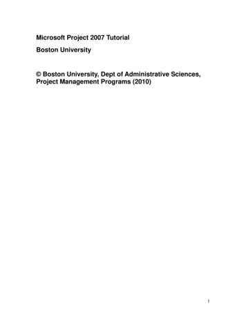
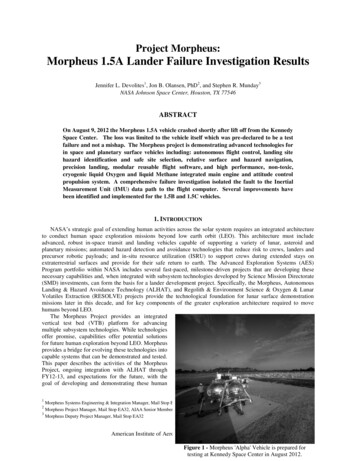
Project Morpheus:Morpheus 1.5A Lander Failure Investigation ResultsJennifer L. Devolites1, Jon B. Olansen, PhD2, and Stephen R. Munday3NASA Johnson Space Center, Houston, TX 77546ABSTRACTOn August 9, 2012 the Morpheus 1.5A vehicle crashed shortly after lift off from the KennedySpace Center. The loss was limited to the vehicle itself which was pre-declared to be a testfailure and not a mishap. The Morpheus project is demonstrating advanced technologies forin space and planetary surface vehicles including: autonomous flight control, landing sitehazard identification and safe site selection, relative surface and hazard navigation,precision landing, modular reusable flight software, and high performance, non-toxic,cryogenic liquid Oxygen and liquid Methane integrated main engine and attitude controlpropulsion system. A comprehensive failure investigation isolated the fault to the InertialMeasurement Unit (IMU) data path to the flight computer. Several improvements havebeen identified and implemented for the 1.5B and 1.5C vehicles.1. INTRODUCTIONNASA’s strategic goal of extending human activities across the solar system requires an integrated architectureto conduct human space exploration missions beyond low earth orbit (LEO). This architecture must includeadvanced, robust in-space transit and landing vehicles capable of supporting a variety of lunar, asteroid andplanetary missions; automated hazard detection and avoidance technologies that reduce risk to crews, landers andprecursor robotic payloads; and in-situ resource utilization (ISRU) to support crews during extended stays onextraterrestrial surfaces and provide for their safe return to earth. The Advanced Exploration Systems (AES)Program portfolio within NASA includes several fast-paced, milestone-driven projects that are developing thesenecessary capabilities and, when integrated with subsystem technologies developed by Science Mission Directorate(SMD) investments, can form the basis for a lander development project. Specifically, the Morpheus, AutonomousLanding & Hazard Avoidance Technology (ALHAT), and Regolith & Environment Science & Oxygen & LunarVolatiles Extraction (RESOLVE) projects provide the technological foundation for lunar surface demonstrationmissions later in this decade, and for key components of the greater exploration architecture required to movehumans beyond LEO.The Morpheus Project provides an integratedvertical test bed (VTB) platform for advancingmultiple subsystem technologies. While technologiesoffer promise, capabilities offer potential solutionsfor future human exploration beyond LEO. Morpheusprovides a bridge for evolving these technologies intocapable systems that can be demonstrated and tested.This paper describes the activities of the MorpheusProject, ongoing integration with ALHAT throughFY12-13, and expectations for the future, with thegoal of developing and demonstrating these human1Morpheus Systems Engineering & Integration Manager, Mail Stop EA34Morpheus Project Manager, Mail Stop EA32, AIAA Senior Member3Morpheus Deputy Project Manager, Mail Stop EA3221American Institute of Aeronautics and Astronautics: SPACE 2013Figure 1 - Morpheus 'Alpha' Vehicle is prepared fortesting at Kennedy Space Center in August 2012.
spaceflight capabilities with robotic missions to the lunar surface.The Morpheus Project provides a liquid oxygen (LOX) / liquid methane (LCH4) propelled vehicle that, whenleveraging subsystem designs developed by other VTBs such as the Marshall Space Flight Center’s (MSFC) MightyEagle Lander, may be developed into reusable platforms for in-space transit and/or planetary landing for multiplemissions and payload capacities. Such platforms could directly support robotic missions and would eventuallymature into capabilities advantageous for manned missions.The LOX/methane propulsion system is one of two key technologies that Morpheus is designed to integrate anddemonstrate. The Morpheus LOX/methane propulsion system can provide a specific impulse during space flight ofup to 321 seconds; it is clean-burning, non-toxic, and cryogenic, but space-storable. Additionally, for future spacemissions the lox and/or methane could be produced in situ on planetary surfaces, and the oxygen is compatible onboard with life support systems and power generation. These attributes make LOX/methane an attractive propulsiontechnology for a lander of this scale.ALHAT, the primary Morpheus payload, provides the second key technology: autonomous landing and hazardavoidance. When landing autonomously on any planetary or other surface, the vehicle must be able to identify a safelanding site that is free of large boulders, rocks, craters, or highly sloping surfaces. Morpheus is designed to carryALHAT sensors and software supporting tests that will demonstrate an integrated vehicle capability to perform thesetasks.2. SYSTEM DESCRIPTIONThe VTB system elements include the flight test vehicle, ground systems, and operations.A. VehicleMorpheus design and development began in June 2010, primarily by an in-house team at NASA’s JohnsonSpace Center. The current iteration is the Morpheus ‘1.5 Bravo’ vehicle, and system description references thecurrent vehicle build.Morpheus is a “quad” lander design with four tanks and a single engine. The primary structure consists ofwelded aluminum box beams, machined parts, and aluminum plate. The landing struts have honeycomb crush padsin the feet to attenuate landing loads. The propellant tanks are made of welded aluminum hemispheres. The avionicsand GN&C components are located on a plate that spans the top deck of the primary structure.The propulsion system uses an impinging element-type engine design, with liquid oxygen and methane as thepropellants. The engine is film-cooled and operates as a blow-down system producing up to 5000 lbf of thrust. Twoorthogonal electromechanical actuators (EMAs) gimbal the engine to provide thrust vector control of lateraltranslation and pitch and yaw attitudes. LOX/LCH4 pencil thrusters fed from the same propellant tanks provide rollcontrol with a redundant set of helium jets that use the pressurized helium in the propellant tanks onboard as abackup system. Varying the engine throttle setting provides vertical control of ascent and descent rates.The avionics and power subsystems include the flight computer, data recording, instrumentation,communications, cameras, and batteries. The flight computer is an AITech S900 CompactPCI board with aPowerPC 750 processor. Up to 16 GB of data can be stored on board. Data buses include RS-232, RS-422, Ethernet,and MIL-STD-1553. Multiple channels of analog and digital inputs are used for both operational and developmentalflight instrumentation, including temperature sensors, pressure transducers, tri-axial accelerometers, and straingauges. Wireless communications between ground operators and the vehicle use a spread spectrum frequency band.Two on-board cameras provide views of the engine firing during testing. Eight lithium polymer batteries providevehicle power.The GN&C sensor suite includes a Javad Global Positioning System (GPS) receiver, an International SpaceStation (ISS) version of Honeywell’s Space Integrated GPS/INS (SIGI), a Systron Donner SDI500 InertialMeasurement Unit (IMU), and an Acuity laser altimeter. The vehicle is able to determine position to less than onemeter, velocity to less than three cm/second, and attitude knowledge within 0.05 degrees.The vehicle software is architected around Goddard Space Flight Center’s (GSFC) Core Flight Software (CFS).GSFC designed CFS as a set of reusable software modules in a flexible framework that can be adapted to variousspace applications. Morpheus software developers built upon CFS by adding custom application code unique to theMorpheus vehicle and mission design.The initial Morpheus VTB 1.0 configuration was tested from April 2011 through August 2011. In late 2011 andearly 2012, the team began upgrading the VTB to the Morpheus 1.5 configuration, including sequentially higherperformance HD4 and HD5 engines, an improved avionics and power distribution design, the addition ofLOX/methane thrusters for roll control, and the incorporation of the ALHAT sensors and software. In August 2012,the original vehicle was lost in a test crash. The vehicle was rebuilt with over 70 upgrades and is designated as the2American Institute of Aeronautics and Astronautics: SPACE 2013
Morpheus 1.5 ‘Bravo’ vehicle. This vehicle configuration is currently in testing as described in later sections. A‘Charlie’ vehicle is also under construction.B. Ground SystemsThe VTB flight complex (VFC) includes 20’ x 20’ concrete pads located on a section of the JSC antenna rangenear an old Apollo-era antenna tower. About 2000 feet away is the Morpheus control center for on-site field testingat JSC, the small 2-story building 18 that was formerly used for rooftop GPS testing and storage. The main upstairsroom has a window that looks directly out onto the test area, making it highly suitable as the operations “frontroom,” configured with three rows ofcomputertablesforoperatorworkstations. An adjacent room servesas the “back room” for supportpersonnel.The operator workstations useGSFC’s Integrated Test and OperationsSystem (ITOS) ground software. LikeCFS, ITOS was developed as groundcontrol and display software for GSFCspace vehicles and has been madeavailable to other projects at NASA.Figure 3 – Typical Morpheus ground support equipmentITOS is individually configured on eachworkstation to display vehicle telemetry and information unique to each operator position.During each test, the Morpheus Project streams mission telemetry, voice loops, and video from the testingcontrol center to JSC’s Mission Control Center (MCC) over dedicated wireless and wired networks. From there,data and video can be made available to internal and external networks for NASA personnel and the general public.A thrust termination system (TTS) is employed both for range safety and independent test termination purposes.Closing either of two motorized valves in the TTS will shut off the flow of liquid oxygen and methane to the engineand terminate engine thrust. These TTS valves are completely independent from the rest of the vehicle systems andcommanded using separate Ultra High Frequency (UHF) radios. The commands to initiate thrust termination aresent from a control unit located in the operations center during any live engine testing.Ground systems also include propulsion ground support equipment (GSE). The consumables required for anengine test include liquid oxygen, liquefied natural gas, helium, liquid nitrogen, and gaseous nitrogen. The powerGSE is a portable ground power cart that is used to supply power to the vehicle until the test procedures call for aswitch to internal vehicle power. The ground power cart uses heavy duty batteries and can provide up to 72 amphours of power for pre- and post-test activities. The mechanical GSE includes a rented crane for tethered or hot fire /hold-down testing. For tethered tests, an energy absorber is placed between the vehicle and the crane boom arm. Theenergy absorber is an aluminum piston and cylinder with cardboard honeycomb material that can attenuate up to10,000 lb. This load attenuation protects the vehicle and crane structures in the event engine thrust needs to beterminated prematurely, causing the vehicle to drop to the end of the tether.Ground systems also include a variety of transportation assets, provided primarily by JSC Center Operations.C. OperationsThe final element of the Morpheus system is Operations. Nine primary operator positions are staffed by teammembers: test conductor (TC), operator (OPS), propulsion (PROP), avionics, power and software (APS), guidance,navigation and control (GNC), ground control (GC), two range safety officers (RSO-1 and RSO-2), and the flightmanager (FM). During tests with payloads aboard, another position may be included, such as one for ALHAT. Eachposition is certified throughspecific training.Certification is also requiredfor three pad crew (PAD)positions. PAD-1 is the pad crewleader,responsibleforcommunicating directly with thetest conductor during operationsand ensuring each procedural stepFigure 4 – Morpheus Control Centeris executed at the pad. PAD-2 and3American Institute of Aeronautics and Astronautics: SPACE 2013
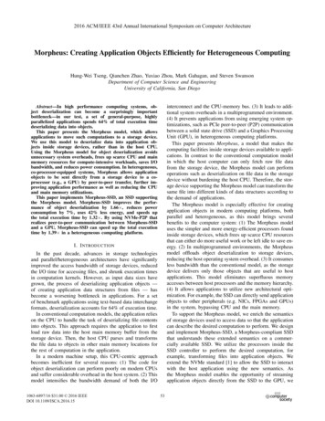
PAD-3 provide support to PAD-1, and conduct all handling of cryogenic fluids and most other consumables.On test days, many other JSC and Morpheus team personnel serve in various functions. JSC riggers supportvehicle transportation and crane operations. Support personnel for each subsystem monitor data or help out duringtesting in the “back room” of the control center. Other team members stand by for potential troubleshooting ifproblems arise.3. MORPHEUS TEST CAMPAIGNMorpheus testing includes three major types ofintegrated tests: hot-fire, tether, and free-flight.A. Hot-fire TestingDuring hot-fire testing the vehicle is completelyrestrained from movement and the primary focus is to testthe LOX/methane propulsion system. In thisconfiguration a crane is used to suspend the vehicle abovethe ground to provide clearance for the vehicle exhaustplume. The vehicle is also constrained from below usingstraps anchored to the ground that prevent vertical andlateral vehicle motion.Figure 5 shows the vehicle during test in the hot-fireFigure 5 – Morpheus in standard Hot-fire TestConfigurationconfiguration. The vehicle is suspended approximately 20’above a concrete pad by a crane outfitted with shielding toprevent damage from flames or debris during the test firing.Additional restraints are attached below the vehicle made ofnylon overwrapped with fireproof insulation or chains.The objectives for hot-fire tests include demonstrationof the igniter, engine ignition, performance at varied throttlesettings and burn duration tests. The Morpheus project testapproach limits testing on a dedicated engine test stand andemphasizes a quick transition to integrated vehicle tests.Testing on the vehicle promotes optimization of engineperformance for the actual vehicle propulsion feed systemFigure 6 – Morpheus in Ground Hot-fire Testinstead of the test stand system. It also allows gimbalConfigurationsweeps to evaluate the integrated performance of theactuators under load. The majority of engine characterization is conducted onthe vehicle, essentially making the hot-fire configuration the primary enginetest stand for the Morpheus Project.A second hot-fire configuration was also developed to test the thermal andvibroacoustic environments at liftoff. In this case, the vehicle remains static onthe ground, chained to the launch pad. The engine is run for only a few secondsat maximum thrust to envelope any environments expected on an actual launchattempt. One such test of the ‘Bravo’ vehicle over a flame trench is depicted inFigure 6.B. Tether TestingFor tether tests the vehicle is suspended from a crane as shown in Figure 4to enable testing of the propulsion and integrated GN&C without the risk of avehicle departure or crash. The goal of these tests is typically to ascend 5 to 15feet vertically and up to 10 feet laterally and hover in place for a preprogrammed duration. Upon successful completion of the hover, the vehicledescends and “lands” at the end of the tether.Due to the potential dynamic loads during tethered flight, a substantiallylarger 120-ton crane is used for this testing. An energy absorber in line with theFigure 7 – Morpheus 1.5‘Bravo’ executing a TetherTest in July 20134American Institute of Aeronautics and Astronautics: SPACE 2013
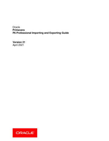
tether reduces the loads on both the crane and Morpheus vehicle and helps prevent damage to either asset.Tether testing provides the first opportunity to perform integrated testing of the Morpheus vehicle with closedloop GN&C. The primary objective of tether testing is to demonstrate 6 degree-of-freedom (DOF) GN&C forvertical translation, hover and simulated landing operations. An additional objective is to understand and rapidlyrefine the integrated performance of avionics, propulsion, and GN&C without risk of a vehicle crash.C. Free-Flight TestingMorpheus “free-flights” demonstrate the fully integrated flight capability of the vehicle with no restraints. Freeflight safeguards are automatic on-board aborts, remotely commanded aborts, as well as the redundant andindependent TTS that can be activated by spotters who visually determine trajectory deviations. A variety of freeflight trajectories can be flown to incrementally build up to a fully functional Morpheus lander capable of flyingplanetary landing trajectories.4. MORPHEUS 1.0 TESTCAMPAIGNDuring the Morpheus 1.0 testcampaign, a series of three hot-firetests was conducted to refinepropulsion system performance. Thiswas also the first opportunity to testvehicle hardware and softwaretogether. Due to the fast pace ofdevelopment, these tests were used asverification tests for numeroussoftware routines.The Morpheus team completedthese three hot-fire tests in 8 days andsuccessfully demonstrated all testobjectives except for handover frompropulsion to GN&C. The teamquickly resolved all issues andconfirmed solutions in subsequenttests,gaining valuablevehicleFigure 8 – Morpheus Tether Test 2 (TT2); and Tether Test 5 (TT5)operations experience and confidenceto proceed with tether testing.Immediately following the hot-fire tests, five tether tests were conducted between April 25th and June 1st, 2011,with the primary objective to demonstrate stable 6-DOF GN&C. The rapid schedule of the first four tests was drivenby a demonstration flight planned for the JSC Innovation Day event on May 4th.The most dramatic tether test in this test campaign was TT2. Immediately upon engine ignition, an H-bridgecircuit controlling the throttle valve failed fully open ( 100% throttle). The vehicle rapidly ascended and anasymmetric bungee arrangement caused a pitching moment. When the ignition sequence was complete and controlwas handed over to GN&C, the vehicle was already in an unrecoverable trajectory. To make matters worse, theGN&C system contained a 90-degree clocking error in an IMU coordinate frame, preventing it from stabilizing thevehicle motion.Morpheus 1.0 (2011): 290 sec HD3 Engine Burn TimeThis uncontrolledmotioncontinueddespiteon-boardsoftware and groundcommands for soft andhard abort and engineshutdown.TheseHot Fire 1Hot Fire 2Tether 1Tether 2Tether 3Tether 4Tether 5Tether 6primary abort methodsApril 14April 19April 25April 27May 3May 4June 1August 31rely upon shutting the103 sec54 sec20 sec13 sec20 sec29 sec40 sec11 secthrottle valve, whichwas stuck open. AfterFigure 9. Morpheus 1.0 Test Summary5American Institute of Aeronautics and Astronautics: SPACE 2013
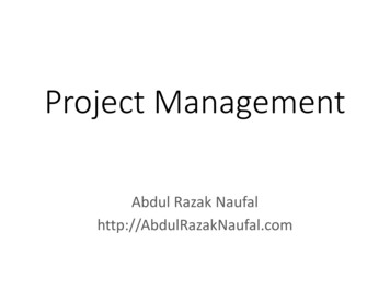
13 seconds of erratic “tetherball” flight, engine thrust was terminated by manual activation of the wired TTS.The team would not have chosen such dynamic test conditions. Yet this “test failure” provided a trainingopportunity for the team to execute a safe abort, and identified key systems issues, enabling the team to improve theengine throttle valve design and correct the navigation frame transformation error. No vehicle or property damageresulted from this test, and the team turned around the VTB for another test in less than a week.The vehicle was better behaved during TT5, successfully completing a full duration run with nominal engineshutdown after 42 seconds. Hover performance was improved, producing only a minor wobble with a period ofapproximately 3.2 seconds. The engine performed nominally and reached a steady-state temperature for the firsttime during VTB 1.0 testing. Testing of the 1.0 configuration came to an end when the HD3 engine suffered a burnthrough event during throttle-up for tether test 6. A new engine design iteration, new avionics, GNC, software, andother upgrades were incorporated onto the vehicle to form the 1.5A vehicle assembly.5. MORPHEUS 1.5 ‘ALPHA’ TEST CAMPAIGNThe Morpheus 1.5A test campaign began in February 2012. Three hot fire tests, one ground hot fire and fourteentether tests were performed, accumulating over 870 seconds of runtime on the HD4 engine. The tether tests wereopportunities for the design team to continue to characterize and improve the interaction between the GN&C andpropulsion systems. Table 2 lists the test summary for Morpheus 1.5 ‘Alpha’.After HF5 confirmed the performance of the new HD4 engine, the team began the assessment of the integratedVTB 1.5 performance in tethered hover tests. Notable tests include TT9, which revealed a GN&C algorithm issuethat caused the vehicle to exceed the altitude constraint, leading to activation of the TTS to abort the test. TT9proved the value of the in-line energy absorber and the very robust vehicle construction in preventing damage toVTB 1.5 as it dropped to the end of the tether.Morpheus 1.5 (2012): 850 sec HD4 Engine Burn TimeHot Fire 5Tether 7Tether 8Tether 9Hot Fire 6Tether 10Tether 11Tether 12February 27March 5March 13March 16April 2April 5April 11April 1840 sec30 sec55 sec47 sec5 sec62 sec56 sec67 secTether 13May 262 secTether 14May 866 secKSCTether 15Tether 16Tether 17RCS HF1Tether 18Tether 19Tether 20May 10June 11June 18July 3July 6July 17August 3Free Flight 1 Free Flight 2August 7August 960 sec41 sec63 secMethane RCS49 sec72 sec63 secSoft abortLOVFigure 10. Morpheus 1.5 ‘Alpha’ Test SummaryAs the first test of Morpheus sitting on the launch pad in liftoff configuration, HF6 provided valuable groundeffects and overpressure data, and revealed that the footpads were insufficiently insulated. This test served as aproto-qual test, intended to envelope the environments expected to be experienced during free flight launches.Tether tests 10 through 15 demonstrated increasing vehicle controllability and stability with nominal engineshutdowns as the team refined GN&C and EMA parameters. With satisfactory vehicle performance, the ALHATsuite of sensors was integrated with the vehicle for two tether tests. This initial integration did identify somehardware and software timing discrepancies that required continued maturation once the sensors were removed fromthe vehicle.With ALHAT integration testing complete, the team prepared for free flight testing by conducting one finaltether test at JSC, shipping the vehicle to KSC, and then conducting a tether test at KSC’s Shuttle Landing Facility(SLF) to verify transportation did not impact vehicle readiness.6American Institute of Aeronautics and Astronautics: SPACE 2013
6. FREE FLIGHTSA. Risk PostureHeading into free flights at KSC, it was important for the project to maintain a consistent risk posture. Thevehicle was built from the beginning as a single-string prototype vertical take-off and landing vehicle. That approachenabled the project to pursue lean development and make advances in design, testing and operations in a more rapidfashion. However, there are inherent risks to the vehicle using this approach. The project put forth significant effortin identifying and mitigating single-point failures that could cause loss of vehicle prior to heading to KSC. Thatincluded substantial subsystem-level testing, all of the tether testing previously described, and system-levelprotoqual testing, such as the ground hotfire test.The primary exception to the single-string philosophy included safety systems in subsystems such as pressuresystems and range safety. Pressure systems have redundant pressure relief components built in. There is also a dualredundant thrust termination system (TTS) on board the vehicle that that includes 2 independent valves in thepropulsion system, either of which can cut engine thrust on command. This exemplifies the project emphasis onsafety, even in light of accepting additional risk to the test vehicle itself.The purpose of the ground hot-fire test was specifically to envelope the environments expected during liftoff of afree flight. HotFire 6 did exactly that. The vehicle was outfitted with a variety of instrumentation, includingaccelerometers, microphones and thermocouples, and was chained to the ground launch pad. Upon ignition, theengine was throttled up to 100% and remained for 5 seconds to conservatively characterize the environment. Beyondthis type of testing, there were no standard qualification tests of components due to the prototype nature of thevehicle.In addition to the actual testing accomplished, it was important to ensure all stakeholders were fully aware of therisk posture for free flights. The loss of the Morpheus 1.5A vehicle was pre-declared a test failure and not a mishapas long as no personnel were injured or infrastructure was damaged. In this light, the loss of vehicle was consideredan acceptable risk for the purpose of advancing our understanding of all of the components of integrated vehicleperformance.B. Free Flights 1 & 2In preparation for the final demonstration flights with ALHAT, a hazard field – replicate of an area of the lunarsurface – was constructed off the end of the SLF runway as the approach field for the Morpheus free flight testing.The initial test campaign at KSC, though, was intended to incrementally expand the flight envelope to demonstrateadequate vehicle performance beforereintegrating the expensive ALHATsensors.On August 7, 2012, Free Flight 1was aborted just after liftoff due to afaulty transient engine burn-throughindication. The vehicle detected theindication and soft-aborted as designed– after rising less than a foot off of thepad. The erroneous indication wasreadily fixed, as was an issue identifiedwith the crushable footpads used forimpact attenuation on landing. In 24hours, personnel at KSC designed anddeveloped some thermal protection forthe footpads to ensure they would lastthrough any flight profile.Figure 9 – Shuttle Landing Facility at KSC: Morpheus Free Flight 1atignition; and Free Flight 2 after it crash landed.7American Institute of Aeronautics and Astronautics: SPACE 2013
Free Flight 2 wasattempted two days later, onAugust 9. In this test, thedata from the only activeIMU was lost 0.6 secondsinto flight, causing thevehicle to lose control andcrash.ThecombinedJSC/KSC team immediatelyexecuted the pre-rehearsedemergency action plan toprotectpersonnelandproperty, so damage waslimited to vehicle hardware.The timeline of eventsduring takeoff is shown inTable 1.C. Debris RecoveryAt the conclusion ofemergencyresponseTable 1 – Free Flight 2 Timelineactivities, with the vehicleand all other hardware safed,the Morpheus team reassembled into a debris recovery team. Data was secured from the control center and from thevehicle where possible, as well as all video sources. The debris field was methodically mapped over two days and alldebris recovered. A polar grid was established and debris was catalogued and weighed. Nearly all debris wascontained within a 50m radius. Results of the debris assessment verified that the blast models used by the project toestablish safe distances for personnel were indeed conservative. This data has been turned over to numerousinterested parties to help refine various blast models that have been developed.The entire vehicle waslost, with the exception of ahandful of parts that wererecovered. The onboard SDcard experienced too muchheat damage for datarecovery, but the APUSolid State Disk Drive dataandDFIboxwererecovered. Since the enginecontinued to burn onimpact,cryogenicpropellants were flowingthrough it. As a result, theHD4 engine injector wasrecovered and reusable, andhas been incorporated intothe rebuilt engine currentlypoweringthe‘Bravo’vehicle.Figure 10 – Free Flight 2 Debris MapD. Proximate CauseIt was evident immediately upon loss of the vehicle that the onboard IMU has stopped communicating with thecontrol computer 0.6 seconds after liftoff. A thorough investigation confirmed this diagnosis. All evidence points toproper performance of the power and propulsion subsystems, and software performed exactly as designedthroughout the brief flight. There were no indications of instrumentation loss beyond the IMU data and no evidenceof structural failure. Winds and weather were benign at the time of flight.8American Institute of Aeronautics and Astronautics: SPACE 2013
As a result, the proximate cause was isolated to the loss of navigation data, required by the vehicle to maintainits navigation state and attitude knowledge. Without that data, the vehicle is flying blind and responding only to itslast known state and attitude. However, there are several components within the string of navigation data, andforensics did not identify with certainty the absolute cause.The IMU instrument itself, 1553 bus hardware and couplers, wiring, computer interface, and software are allpotential components that could have produced the flight signature. Forensic analysis of the recovered AvionicsPower Unit (APU), which includes the primary computer, identified good continuity in most harnesses even afterthe crash. Such study could not be completed on the other components as they were unrecoverable.The investigation into the proximate cause was guided by a thorough fault tree assessment. The results of theinvestigation yielded the probable failure as a hardware component failure outside of the APU most likely as theresult of high vibroacoustic environments at liftoff. The affect could have been acute or the accumulation of damagedue to repeated exposure to the vibration environment.7. FINDINGS AND CORRECTIVE ACTIONSThe engineering investigation described herein was accomplished over three months and incorporated inputsfrom the entire Morpheus team as well as independent expert reviewers. The findings and corrective actions thatresulted from the investigation are summarized in Table 2.8. MORPHEUS 1.5 ‘BRAVO’ UPGRADESThe loss of Morpheus 1.5 ‘Alpha’ resulted in a rebuild effort to return to testing. 70 upgrades were approved for
NASA Johnson Space Center, Houston, TX 77546 ABSTRACT On August 9, 2012 the Morpheus 1.5A vehicle crashed shortly after lift off from the Kennedy Space Center. The loss was limited to the vehicle itself which was pre-declared to be a test failure and not a mishap. The Morpheus project is demonstrating advanced technologies for