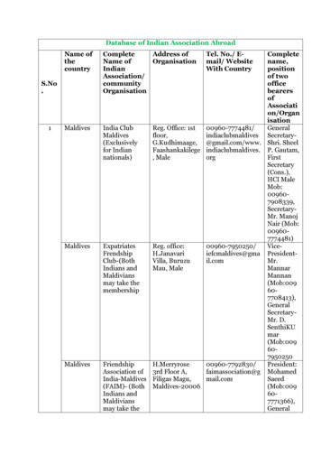
Transcription
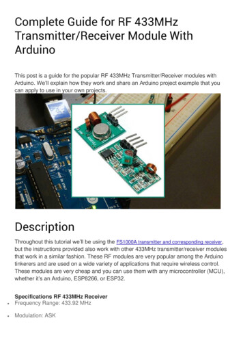
Complete Guide for RF 433MHzTransmitter/Receiver Module WithArduino65 SharesThis post is a guide for the popular RF 433MHz Transmitter/Receiver modules withArduino. We’ll explain how they work and share an Arduino project example that youcan apply to use in your own projects.DescriptionThroughout this tutorial we’ll be using the FS1000A transmitter and corresponding receiver,but the instructions provided also work with other 433MHz transmitter/receiver modulesthat work in a similar fashion. These RF modules are very popular among the Arduinotinkerers and are used on a wide variety of applications that require wireless control.These modules are very cheap and you can use them with any microcontroller (MCU),whether it’s an Arduino, ESP8266, or ESP32. Specifications RF 433MHz ReceiverFrequency Range: 433.92 MHz Modulation: ASK
Input Voltage: 5V Price: 1 to 2 Specifications RF 433MHz TransmitterFrequency Range: 433.92MHz Input Voltage: 3-12V Price: 1 to 2Arduino with RF 433MHzTransmitter/Receiver ModulesIn this section we build a simple example that sends a message from an Arduino toanother using 433 MHz. An Arduino board will be connected to a 433 MHz transmitterand will send the “Hello World!” message. The other Arduino board will be connected toa 433 MHz receiver to receive the messages.You need the following components for this example: 2x Arduino – read Best Arduino Starter KitsRF 433MHz Receiver/TransmitterBreadboardJumper wiresYou can use the preceding links or go directly to MakerAdvisor.com/tools to find all theparts for your projects at the best price!Installing the RadioHead Library1.2.3.4.The RadioHead library provides an easy way to work with the 433 MHztransmitter/receiver with the Arduino. Follow the next steps to install that library in theArduino IDE:Click here to download the RadioHead library. You should have a .zip folder inyour Downloads folder.Unzip the RadioHead library.Move the RadioHead library folder to the Arduino IDE installation libraries folder.Restart your Arduino IDEThe RadioHead library is great and it works with almost all RF modules in the market.You can read more about the RadioHead library here.
Transmitter CircuitWire the transmitter module to the Arduino by following the next schematic diagram.Note: always check the pinout for the transmitter module you’re using. Usually, thereare labels next to the pins. Alternatively, you can also take a look at your module’sdatasheet.Transmitter SketchUpload the following code to the Arduino board.#include#include// Not actually used but needed to compileRH ASK driver;void setup(){Serial.begin(9600);// Debugging only
if (!driver.init())Serial.println("init failed");}void loop(){const char *msg "Hello World!";driver.send((uint8 t *)msg, How the transmitter sketch worksFirst, we need to include the RadioHead ASK library.#include RH ASK.h This library needs the SPI library to work. So, we also need to include the SPI library.#include SPI.h After that, we create a RH ASK object called driver.In the setup() we initialize the RH ASK object by using the init() method. We usean ifstatement and a print in the Serial Monitor for debugging purposes.Serial.begin(9600); // Debugging onlyif (!driver.init())Serial.println("init failed");In the loop(), we write and send our message. Here, our message is saved onthe msgvariable. Please note that the message needs to be a char type.const char *msg "Hello World!";This message contains the “Hello World!” message, but you can send anything youwant as long as it is in char format.Finally, we send our message as follows:driver.send((uint8 t *)msg, strlen(msg));driver.waitPacketSent();The message is being sent every second, but you can adjust this delay time.delay(1000);Receiver Circuit
Wire the receiver module to another Arduino by following the next schematic diagram.Note: always check the pinout for the receiver module you’re using. Usually, there arelabels next to the pins. Alternatively, you can also take a look at your module’sdatasheet.Receiver SketchUpload the code below to the Arduino connected to the receiver.#include#include// Not actualy used but needed to compileRH ASK driver;void setup(){Serial.begin(9600);// Debugging onlyif (!driver.init())Serial.println("init failed");}void loop(){uint8 t buf[12];
uint8 t buflen sizeof(buf);if (driver.recv(buf, &buflen)) // Non-blocking{int i;// Message with a good checksum received, dump it.Serial.print("Message: ");Serial.println((char*)buf);}}How the receiver sketch worksSimilarly to the previous sketch, you start by including the necessary libraries:#include RH ASK.h #include SPI.h You create a RH ASK object called driver:RH ASK driver;In the setup(), we initialize the RH ASK object.void setup(){Serial.begin(9600); // Debugging onlyif (!driver.init())Serial.println("init failed");}In the loop(), we need to set a buffer that matches the size of the message we’llreceive. “Hello World!” has 12 characters. You should adjust the buffer size accordinglyto the message you’ll receive (spaces and punctuation also count).uint8 t buf[12];uint8 t buflen sizeof(buf);Then, we check if we received a valid message. If we receive a valid message, we printit in the serial monitor.if (driver.recv(buf, &buflen)) {int i;// Message with a good checksum received, dump it.Serial.print("Message: ");Serial.println((char*)buf);}
DemonstrationIn this project the transmitter is sending a message “Hello World!” to the receiver viaRF. Those messages are being displayed in receiver’s serial monitor. The followingfigure shows what you should see in your Arduino IDE serial monitor.Wrapping UpYou need to have some realistic expectations when using this module. They work verywell when the receiver and transmitter are close to each other. If you separate them toofar you’ll lose the communication. The communication range will vary. It depends onhow much voltage you’re supplying to your transmitter module, RF noise in yourenvironment, and if you’re using an external antenna.
Decode and Send 433 MHz RF Signalswith ArduinoThis guide shows how to use an Arduino to decode 433 MHz signals from RF remotes,and send them with an Arduino and a 433 MHz transmitter to remotely control mainsswitches outlets.Why Decoding RF Signals?I’ve tried different methods of controlling the mains voltage, but some of the methodsrequire: Experience dealing with AC voltage Opening holes in your wall/ceiling/switches Modifying the electrical panel Knowing the electrical rules for each countryIt’s difficult to come up with a solution that is safe and works for everyone. One of theeasiest and safest ways to remotely control appliances connected to mains voltage isusing radio frequency (RF) controlled outlets. Why? Using remote controlled outletshave 5 benefits:1. Fairly inexpensive2. Easy to get3. Works with ESP8266 and Arduino
4. Safe to use5. Works in any countryParts RequiredFor this tutorial, you need the following parts: Arduino UNO – read Best Arduino Starter Kits433 MHz RF Remote controlled sockets433 MHz transmitter/receiverBreadboardJumper wiresNote: you need to buy remote controlled outlets that operate at a RF of 433MHz. Theyshould say the operating RF either in the product page or in the label.ExampleHere’s how they look:Setting the RF ChannelsI’ve set my remote control to the I position.
The outlets must be both on the I position. I’ve selected channels 3 and 4 for the outlets(you can use any channel you want).
If you plug them to an outlet, you should be able to control the remote controlled outletswith your remote control.Installing the RC Switch LibraryThe RC Switch library provides an easy way of using your ESP8266, ESP32, orArduino to operate remote radio controlled devices. This will most likely work with allpopular low-cost power outlet sockets.1. Click here to download the RC Switch library. You should have a .zip folder inyour Downloads folder2. Unzip the .zip folder and you should get rc-switch-master folder3. Rename your folder from rc-switch-master to rc switch4. Move the rc switch folder to your Arduino IDE installation libraries folder5. Then, re-open your Arduino IDEOpening the Decoder SketchYou need to decode the signals that your remote control sends, so that the Arduino orESP8266 can reproduce those signals and ultimately control the outlets.The library comes with several sketch examples. Within the Arduino IDE software, youneed to go to File Examples RC Switch ReceiveDemo Advanced. This nextsketch opens:/*Example for receivinghttps://github.com/sui77/rc-switch/If you want to visualize a telegram copy the raw data andpaste it into http://test.sui.li/oszi/*/#includeRCSwitch mySwitch RCSwitch();void setup() d loop() {if (mySwitch.available()) {// Receiver on interrupt 0 that is pin #2
output(mySwitch.getReceivedValue(), Having an Arduino board connected to your computer follow these instructions:1.2.3.4.Go to the Tools tabSelect Arduino UNO boardSelect the COM portPress the Upload button.Decoder – SchematicsAfter uploading the sketch, connect an 433MHz RF receiver to Digital Pin 2 of yourArduino UNO board:Decode RF Signals (codes)Open the Arduino IDE serial monitor and start pressing the buttons. As shown in thevideo demonstration below:
After pressing each button one time, you can see the binary code for each button (it’shighlighted in red):Save your binary codes for each button press (you can also use the Decimal or TriState codes): Button 3 ON (24Bit) Binary: 000101010101000101010101 Button 3 OFF (24Bit) Binary: 000101010101000101010100 Button 4 ON (24Bit) Binary: 000101010101010001010101 Button 4 OFF (24Bit) Binary: 000101010101010001010100Save your Pulse Length: 416 Microseconds and Protocol: 1.Send the RF Signals (codes)You’ll need to customize the next sketch with your binary codes, pulse length andprotocol:/*Based on the SendDemo example from the RC Switch deRCSwitch mySwitch RCSwitch();void setup() {Serial.begin(9600);// Transmitter is connected to Arduino Pin #10mySwitch.enableTransmit(10);// Optional set pulse length.mySwitch.setPulseLength(REPLACE WITH YOUR PULSE LENGTH);
// Optional set protocol (default is 1, will work for most outlets)mySwitch.setProtocol(REPLACE WITH YOUR PROTOCOL);// Optional set number of transmission repetitions.// mySwitch.setRepeatTransmit(15);}void loop() {// Binary code - button ay(1000);// Binary code - button ay(1000);}In my case, the pulse length and protocol looks like this:// Optional set pulse length.mySwitch.setPulseLength(416);// Optional set protocol (default is 1, will work for most outlets)mySwitch.setProtocol(1);Here’s a binary sender example (you have to replace with your own binary ender SchematicsAfter uploading the sketch to your Arduino board, assemble this circuit:
Both of your outlets should be turning on and off continuously.
After pressing each button one time, you can see the binary code for each button (it’s highlighted in red): Save your binary codes for each button press (you can also use the Decimal or Tri-State codes): Button 3 ON (24Bit) Binary: 000101010101000101010101 Button 3 OFF