Transcription
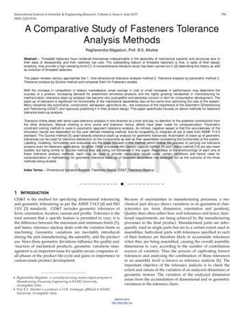
IMAGINiT Technologies White PaperTolerance Modeling with Inventor1Tolerance Modeling with InventorThe ability to work in a virtual Digital Prototype is certainly an invaluable tool for assembly ideation andvisualization. Analysis tools such as Inventor’s ability to check for potential interferences and driveassembly locational constraints through a range of sizes and positions can help a designer ensure thatvalid form, fit and function considerations are honored. This virtual prototyping in turn reduces designcycle times, time to market, and ultimately, cost. I am confident using these techniques made me abetter Product Designer.However, performing these analyses on parts modeled to a nominal size is insufficient and error‐prone.Designers will place allowable tolerances on parts based on manufacturing processes, materialproperties, and cost factors. How, then, do I capture and incorporate these factors into my designverification?Defining the Tolerance ModelDimensional tolerancing is often achieved through the addition of tolerances to individual dimensions and/or theuse of a global tolerance table on a drawing. By adding the requisite dimensional tolerances to the drivingparametric dimensions within the model itself, a designer will be much better equipped to physically simulate andevaluate the impact of the change on the model and its related componentry. This process allows you to: Apply and set tolerances on a global or per‐dimension basis to min, max, median, or nominal settings toevaluate fit in each state. This approach recognizes and accounts for the fact that not all machiningprocesses will manufacture to an identical tolerance within the same part, or batch of parts.Account for tolerance stack‐up across a series of features or parts.Highlight and underline all dimensions whose tolerances are not currently set to nominal.Automatically insert tolerances into a detail drawing.Reduce if not eliminate physical prototypes, revisions, scrap and rework time. IMAGINiT Technologieswww.rand.com/imaginit
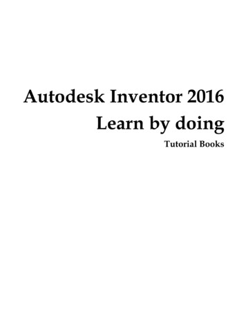
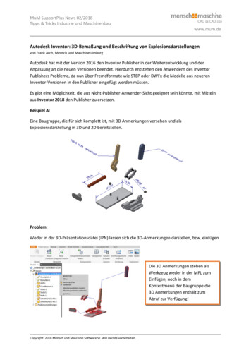
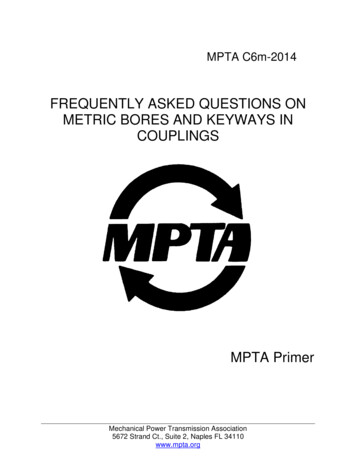
IMAGINiT Technologies White PaperTolerance Modeling with Inventor2Albeit a very powerful concept, I am going to use a very simple, straightforward example here.This process starts at the sketch level as we first add dimensions. Upon placing the relevant dimensions, in theEdit Dimension dialog, enter a unique Parameter name (highly recommended) and its corresponding nominalvalue as shown below in Figure 1. (Note: On older Inventor releases, you may have to already have pre‐defined aUser Parameter, or renamed a Model Parameter, for this purpose.)Figure 1As mentioned, tolerances can be created on a global (document‐wide) or added (or overwritten) on a per‐dimension basis.GLOBAL TOLERANCING:To add a global tolerance, select “Document Settings” from the Tools menu tab as shown below in Figure 2.Figure 2 IMAGINiT Technologieswww.rand.com/imaginit
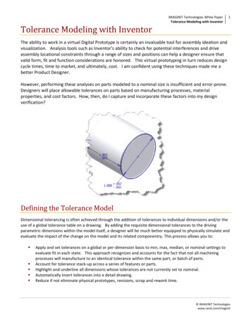
IMAGINiT Technologies White PaperTolerance Modeling with Inventor3In the Document Settings dialog box, select the Default Tolerance tab (Figure 3).Figure 3In this dialog box, the “Use Standard Tolerancing Values” checkbox allows us to use the precision and tolerancevalues defined on this tab when creating dimensions, and the “Export Standard Tolerance Values” checkbox isused to export dimensions to drawings using the precision and tolerance values set here.In the Linear and/or Angular fields, use the pulldown menus under Precision to select a value and enter thecorresponding tolerance next to it as shown in Figure 4. Add as many as needed.Figure 4(TIP: Consider adding frequently‐used values to your company templates.) IMAGINiT Technologieswww.rand.com/imaginit
IMAGINiT Technologies White PaperTolerance Modeling with Inventor4PER‐DIMENSION TOLERANCING:To add (or override) tolerances on a per‐dimension basis, right‐click on a dimension and select “DimensionProperties” from the context menu (Figure 5).Figure 5This may also be accomplished while in theEdit Dimension dialog box by clicking the right‐arrow and selecting “Tolerance” as seen inFigure 6. Additionally, this method is alsoavailable when using the Edit ModelDimension function on the drawing file.(TIP: Consider that this method is availableany time a dimension is made visible, not onlyin the sketch editing environment, but alsowhen using the “Show Dimensions” option onany feature, making this a practical workflowfor Extrusion depth, Revolve angle, or any Loftor Sweep dimensions.)Figure 6 IMAGINiT Technologieswww.rand.com/imaginit
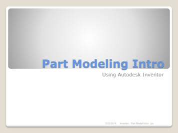
IMAGINiT Technologies White PaperTolerance Modeling with Inventor5In the Dimension Properties dialog box, select theTolerance Type desired from the following choices(Figure 7). DEFAULT – No tolerance specified. SYMMETRIC – Uses the same upper andlower tolerance, i.e., /‐.002. DEVIATION – Uses differing upper and lowertolerance, i.e., .002/‐.001 LIMITS – STACKED – Displays the upper andlower allowable value in a stacked format. LIMITS – LINEAR ‐ Displays the upper andlower allowable value in a hyphenated side‐by‐side fashion. MAX, MIN – Denotes the dimension value asMaximum or Minimum and labels it as such. LIMITS/FITS – Tolerancing method used onshafts and holes. Stacked and Linear displayoptions are available, and, when selected, auser may also enter corresponding Hole andShaft tolerances.Figure 7Enter the appropriate values as shown in Figure 8.Figure 8 IMAGINiT Technologieswww.rand.com/imaginit
IMAGINiT Technologies White PaperTolerance Modeling with Inventor6Now that we have attached tolerances to our dimensions, using either of these methods, how do we actuallyincorporate them into the calculated dimensional value? There are a couple of ways to accomplish this. The firstmethod is to reenter the Dimension Properties dialog box shown earlier in Figure 7. In the upper right corner wewill find an Evaluated Size selection area as shown below.Clockwise from the top these allow me to set the dimension to its Upper(max), Nominal, Lower (min), or Median (min/max average) size.Figure 9An alternate method is from with the Parameters dialog box. The Parameters dialog box is accessed from theManage menu tab (Figure 10).(TIP: This is useful for changing multiple dimensions.)Figure 10 IMAGINiT Technologieswww.rand.com/imaginit
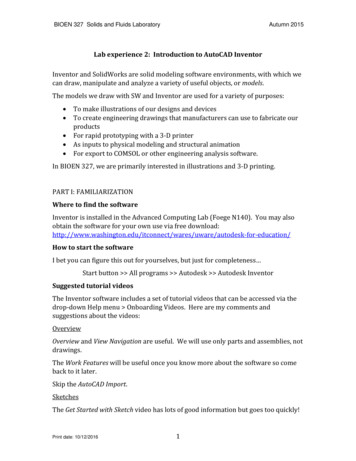
IMAGINiT Technologies White PaperTolerance Modeling with Inventor7The Parameters dialog box, as seen below, also affords the ability to toggle any dimension to its required value.The Reset Tolerance selection in the lower part of this dialog box provides the ability to globally set all dimensionsat once. This is especially useful to reset all values back to their Nominal state after analysis.Figure 11Dimension Display Options in the Sketch and DrawingEnvironmentsThere are several display options available to the user in the Sketch environment that can also carry through tothe drawing. Right‐click anywhere in the Sketch background and you will see a “Dimension Display” option (Figure12).Figure 12 IMAGINiT Technologieswww.rand.com/imaginit
IMAGINiT Technologies White PaperTolerance Modeling with Inventor8The options are as follows: Value: Shows the nominal value of thedimension. Name: Displays the default or user‐definedname of the dimension, such as “d5” or inmy particular example, “HoleDia”. Expression: Displays both Name and currentValue, i.e., “HoleDia 1”. Tolerance: Displays the nominal dimensionvalue including the tolerance added. Note:if there are in fact no tolerances placed onthe dimension, this will look identical to the“Value” setting. Precise Value: Shows and underlines theevaluated dimension value per the currentUpper, Lower, or Median setting, as shownbelow.Figure 13It is useful to note that these tolerance and display settings will carry through to the drawing when dimensionsare retrieved, and when tolerances are defined and selected on the model, they will accurately be reflected whenusing any of Inventor’s Measure commands. IMAGINiT Technologieswww.rand.com/imaginit
IMAGINiT Technologies White PaperTolerance Modeling with Inventor9Performing an Interference CheckTo initiate an Interference Check in Inventor’s assembly environment, select “Analyze Interference” from theInspect menu tab as shown:Figure 14Two discrete sets of objects can be selected at this point. There can be any number of parts in any set. It is alsosometimes convenient to pre‐select some or all the parts in the assembly before invoking the command.Figure 15 IMAGINiT Technologieswww.rand.com/imaginit
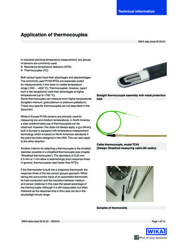
IMAGINiT Technologies White Paper 10Tolerance Modeling with InventorIf any interference is detected, Inventor will highlight the offending bodies and bring up a dialog box stating thenumber and total volume of interference(s) found.Figure 16By expanding the dialog box we see a thorough listing of the exact parts and locations where conflicts are found.Figure 17 IMAGINiT Technologieswww.rand.com/imaginit
IMAGINiT Technologies White Paper 11Tolerance Modeling with InventorBy reiterating this process through all the potential best‐ and worst‐case scenarios, a designer may thoroughlyevaluate and validate designs with minimal time investment.SUMMATIONWe’ve seen that users can take advantage of Tolerance Modeling to accurately predict whether designedassemblies will fit together, perform, and last. We’ve seen that draftsmen can automatically incorporate thisdata within detail drawings to ensure that design intent is correctly conveyed to manufacturing. The benefits interms of reduced design cycle times, change orders, scrap and capital expenditure are self‐evident.Are you putting your Digital Prototypes to work for you?About the Author: Sam HochbergSam Hochberg, Senior Mechanical Application Engineer/Consultant, IMAGINiT ChicagoSam comes from a manufacturing and design background, and has been using 3D CAD modelers asa Product Designer since 1981. While working at Motorola in the mid-80's, he was tasked withdevising and instituting an in-house CAD training program, and also became involved in applicationsupport. He has also taught CAD part- and full-time at the collegiate level, and has worked as anApplication Engineer at Computervision, PTC, and Autodesk resellers since 1987. He brings thiscombination of experience into his current pre- and post-sales support position, and in trainingcustomers believes in not just showing "how" but explaining "why." ATC Certified Instructor Inventor Certified Expert Manufacturing Solutions Implementation Certified Expert AutoCAD and AutoCAD Mechanical PSE CertifiedAll brand names, product names, or trademarks belong to their respective holders.IMAGINiT Technologies is not responsible for typographical or graphical errors that may appear in this document. 2009 IMAGINiT Technologies IMAGINiT Technologieswww.rand.com/imaginit
Account for tolerance stack‐up across a series of features or parts. Highlight and underline all dimensions whose tolerances are not currently set to nominal. Automatically insert tolerances into a detail drawing. Reduce if not elimina