Transcription
BIOEN 327 Solids and Fluids LaboratoryAutumn 2015Lab experience 2: Introduction to AutoCAD InventorInventor and SolidWorks are solid modeling software environments, with which wecan draw, manipulate and analyze a variety of useful objects, or models.The models we draw with SW and Inventor are used for a variety of purposes: To make illustrations of our designs and devicesTo create engineering drawings that manufacturers can use to fabricate ourproductsFor rapid prototyping with a 3-D printerAs inputs to physical modeling and structural animationFor export to COMSOL or other engineering analysis software.In BIOEN 327, we are primarily interested in illustrations and 3-D printing.PART I: FAMILIARIZATIONWhere to find the softwareInventor is installed in the Advanced Computing Lab (Foege N140). You may alsoobtain the software for your own use via free /uware/autodesk-for-education/How to start the softwareI bet you can figure this out for yourselves, but just for completeness Start button All programs Autodesk Autodesk InventorSuggested tutorial videosThe Inventor software includes a set of tutorial videos that can be accessed via thedrop-down Help menu Onboarding Videos. Here are my comments andsuggestions about the videos:OverviewOverview and View Navigation are useful. We will use only parts and assemblies, notdrawings.The Work Features will be useful once you know more about the software so comeback to it later.Skip the AutoCAD Import.SketchesThe Get Started with Sketch video has lots of good information but goes too quickly!Print date: 10/12/20161
BIOEN 327 Solids and Fluids LaboratoryAutumn 2015In Tutorial 1: Sketch Basics, do steps 1-5. Steps 6 & 7 are optional.In Tutorial 2: Navigate the Sketch Environment, has some good tips in step 1, but therest seems a little advanced for us today.Tutorial 3: Use sketch to build a part. If you can do all of these steps, you know howto sketch pretty well. Get through as much as you can.PartsWatch the first section of the Parts video. We will probably not use sheet metal ormulti-body parts BIOEN 327.In Tutorial 1: Part Basics, do Step 2; the others are optional. Tutorials 2 and 3 arealso optional.AssembliesWatch the Assemblies video. It shows many of Inventor’s coolest capabilities.Unfortunately, the tutorial steps themselves assume that you have gone through therest of the tutorials in detail and I do not recommend them at this time.So now you have a choice.If you want to learn more about the Inventor commands by reading, go to Help(pull-down menu) Learn more Learning path. That resource provides a textbased overview of the various functions that you can use in sketches, parts andassemblies.If you want to learn as you go, try the Lab 2 assignment. It assumes that you knowthe basics of sketches, parts and assemblies, and gives some hints to save you timesearching in the Help.Print date: 10/12/20162
BIOEN 327 Solids and Fluids LaboratoryAutumn 2015Lab 2 Assignment : BIOMEDICAL MODELIn this exercise you will create an Inventor (AI) model of a hip implant, or of anotherimplantable structure of similar complexity. A hip implant consists of three mainparts: the stem or spike that fits into the femur, the ball that is permanently affixedto the stem, and the polyethylene cup that fits into the pelvis.Drawing the metal portion of the implant in AI follows a procedure often used tofabricate the spike out of metal. A flat plate of stainless steel or titanium is cut witha water jet to make a sharp-edged basic shape. The edges are then rounded by avariety of machining techniques. The ball is created separately out of the samematerial, and affixed to a post on the upper end of the spike. The metal surface ispolished mechanically and then polished electrochemically. Similarly, in AI we willmake a flat “boss” in the basic shape of the spike, then fillet the edges to produce thedesired smooth model. The ball will be created as a separate part and the two willbe joined in one Assembly. We will not electropolish the drawing, but it is possibleto add surface effects including colors and textures. A beautiful, although notsurgically ideal, rendering can be found on the grabcad.com site.Normally an engineering drawing or solid model is made as part of a largerengineering process that includes defining your need, establishing performancecharacteristics (specifications), considering constraints, proposing a design (whichincludes the drawing), building a prototype, testing it, and refining your design.However, for today we are simply introducing AI so we will use dimensions thathave been published or measured from an existing hip implant.Step 1: Plan your drawingIt is tempting just to start drawing and figure out the dimensions as you go, but it isa good practice to plan your work by sketching the device by hand in your labnotebook. You get to consider options and make notes in a quick and informal waybefore formalizing the layouts in AI. Having that sketch on a dated notebook pagealso shows that the design is your work and that it was created at the time youclaim, which is important if you would like to patent your device. In this exercise,follow these steps:1a. Determine the dimensions you need. These dimensions may be takenfrom an actual implant (the lab has a used specimen) or from sources such asmanufacturers’ literature.11b. Plan the division of parts in the assembly.1c. Sketch each part and label with the appropriate dimensions. Rememberthat some dimensions depend on others, so the order in which you apply thedimensions Print date: 10/12/20161
BIOEN 327 Solids and Fluids LaboratoryAutumn 2015The Zimmer web site lists the stem/spike as Femoral Components and the ball &cup as Acetabular Components. Zimmer’s brochures provide a lot of informationabout the acetabeular shell (metal cup) and liner (polyethylene cup that goes insidethe shell) but the dimensions are difficult to extract from their orderinginformation.1 You may assume that the shell and liner are each 5 mm thick and thatthe ball that is fixed to the stem is 30 mm in diameter.Note that Zimmer has a variety of implant types, and you may choose a knee orshoulder implant if you prefer.Additional eports/srep309.php (Stress analysis ofvarious spike and neck and cup angles)http://www.ncbi.nlm.nih.gov/pubmed/15348867 (study of cup thickness and headdiameter and fusion effectiveness, including trials with irradiated cups. Includesspecimens recovered from cadavers. Thickness of cup is about 10 ue.pdf, page 9.1Print date: 10/12/20162
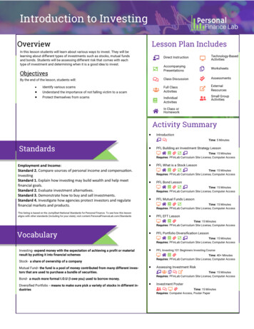
BIOEN 327 Solids and Fluids LaboratoryAutumn 2015Step 2: Drawing the hip implant stem as a partThe following procedure is one of many that you can use to create an implantablestem of approximately the same shape as in the Zimmer documentation. It is notmeant to be a tutorial in how to use Inventor, but rather a guide for one specificapplication. Your dimensions do not have to match the dimensions shown below.Tip 1: make sure you are using the units you want. You may change the units viaTools Document Settings Units.Tip 2: I have hidden the constraints (right click Hide All Constraints) so by defaultyour sketch will have additional icons. You may choose to hide or show as you like.Create a two point rectangle with the lower left corner at the origin; add dimensionseither before you left-click, or by using the Dimension tool (D).Add three points that will define the curve that is cut out of the rectangle to make itsstem shape. Use Dimension to determine their locations.Draw a line between the right two points.Select Arc Tangent and connect the middle point to the lower left point.Use Trim to delete the lower right corner of the rectangle. Just click Trim and thenclick on each segment you want to delete.Print date: 10/12/20161
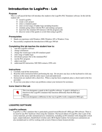
BIOEN 327 Solids and Fluids LaboratoryAutumn 2015The next step is to add a rectangle that will become the stem onto which the ball fits.As setup, I suggest making a construction line that is tangent to the tangent arc youjust created. Construction lines show up as dashed lines, and give you referencelocations, but do not form part of the outline in your finished sketch. To make aconstruction line, click the for construction icon, then start a line at the end of thetangent arc , then adjust the angle until it snaps to being tangent.Select Rectangle 3 Point and draw a rectangle that protrudes off the lower left ofthe stem. After I clicked on the first (right-hand) corner, I extended the bottom edgeof the rectangle along the construction line and set its length, then clicked andextended its width The length of the rectangle doesn’t matter much, but its widthshould be the same as the thickness of the whole piece when you extrude aftersketching (thickness the distance out of the plane of the sketch).First corner becomes fixed here, thenextend the bottom tangent to the curve.I will make my implant 10 mm thick.The 40 mm is arbitrary.Use Trim to delete the inner segments. An alternative to Trim is to right click on asegment and Delete. However, Delete might take out an entire side of a rectangle sosometimes Trim is the best option.Print date: 10/12/20162
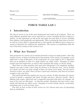
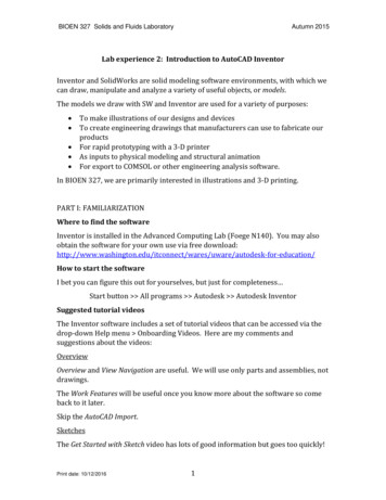
BIOEN 327 Solids and Fluids LaboratoryAutumn 2015The sketch is now done. Note that I also selected all of the lines, right-click Properties and changed the line color to make it easier to see over the black axes.Click Finish Sketch. Click Extrude and enter (or keep) the distance you want. ClickOK. I then went to the View tab Visual Style Shaded with Edges to give the figureshown here. Now save the model!Add small-radius fillets to all edges except on the neck (the exact radius doesn’tmatter). Add fillets to the four side edges of the neck (not the perimeter of theresulting circle at the end of the neck). These fillets should have a radius half of thethickness of the extruded piece. This large fillet propagates along the inner curve -don't worry about it.2 mm fillet5 mm filletNo filletPrint date: 10/12/20163
BIOEN 327 Solids and Fluids LaboratoryAutumn 2015If you like, you may add a disk that will rest atop the femur and keep the stem fromsliding farther into the femur. To do this, you will need to draw a circle that isparallel to, but offset from, the end of the neck (the cylindrical portion).Under the 3D Model tab, click Plane, then select the end of the neck. Enter the offsetdistance; on mine this was a negative number. This gives you a sketch surface thatis offset from the end of the neck. Start a 2D Sketch on this offset plane. This will, bydefault, turn that surface toward you. However, if you like you may choose anotherperspective via the direction cube in the upper right corner.Draw a circle with its center at 0,0 in this sketch plane. Set the diameter you desire,then Finish Sketch. Select and extrude the circle. Add fillets to the disk, and you aredone with the stem!Print date: 10/12/20164
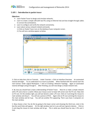
BIOEN 327 Solids and Fluids LaboratoryAutumn 2015Step 3: Draw the ball as a partThere are a few ways to make a ball that is flat on one side and has a hole drilled init. One is to make a sketch with half of the cross-section, Finish Sketch, then Revolveit 360 . While using the Revolve tool, the green outline below is the Profile, and thevertical line is the Axis. If the sketch does not already include a line that is yourdesired axis, then you may either draw a line for this purpose, or use the X, Y or Zaxis as appropriate. These axes are accessible in the Model tree, under Origin.AxisAxisStep 4: Combine the parts in an assembly.After creating a new empty assembly, Place the two parts that you have previouslysaved. Their orientations depend on the plane(s) you chose for making yoursketches back when you created the parts. You want to affix the ball on the stem, sowe Constrain its location there and choose the Insert option.Print date: 10/12/20165
BIOEN 327 Solids and Fluids LaboratoryThis edge will be selection 2Autumn 2015InsertThis edge is selection 1Step 5: Draw the polyethylene cup as a part.The cup is a hemispherical shell whose inner surface matches that of the ball andwhose thickness is 5-10 mm.1 Construction is similar to making the ball, but ofcourse you sketch two concentric arcs before rotating the sketch. The concentricarcs may be generated individually, or by using the Offset function in the sketch.Step 6: Place the cup part in the existing assembly, and this time use a Joint tocombine the two. The type will be Ball, and the two surfaces will be the outside ofthe ball and the inside of the cup.Step 7: Use the material browser to apply asurface appearance to the parts in yourassembly. Select either the cup or the metalassembly, scroll to the material you like andright-click Assign to selection.MaterialbrowserStep 8: Work submission. Collect your parts and assemblies (.ipt and .iam files)and upload them to the Catalyst or Canvas drop box. Show the instructor or TA thatyou have used your notebook to make draft sketches for your parts.1J Mater Sci Mater Med. 1998 Jul;9(7):393-401.Print date: 10/12/20166
Print date: 10/12/2016 1 Lab experience 2: Introduction to AutoCAD Inventor Inventor and SolidWorks are solid modeling software environments, with which we can draw, manipulate and analyze a variety of useful objects, or models. The models we draw with SW and Inventor are used for a variety of purposes: