Transcription
CADComputer Aided Drafting – CADAnup GhoshDepartment of Aerospace EngineeringIndian Institute of Technology KharagpurOctober 15, 2012Anup GhoshComputer Aided Drafting – CAD
CADIntroductionComputer Aided Drafting is a process of preparing a drawing usinga computer.In the field of Mechanical Engineering, the drawing of machinecomponents and layouts are prepared.In the field of Civil Engineering, plans and layouts of thebuildings are prepared.In the field of Electrical Engineering, the layouts of powerdistribution system are prepared.Anup GhoshComputer Aided Drafting – CAD
CADIntroductionComputer Aided Drafting is a process of preparing a drawing usinga computer.In the field of Mechanical Engineering, the drawing of machinecomponents and layouts are prepared.In the field of Civil Engineering, plans and layouts of thebuildings are prepared.In the field of Electrical Engineering, the layouts of powerdistribution system are prepared.Anup GhoshComputer Aided Drafting – CAD
CADIntroductionCAD provides enhanced graphics capabilitiesEase of conceptualizationDrawing can be modified easilyDifferent types of animationsEstimation of bulk materials requiredCalculation of finished surface areas and volumesColors, fonts and other aesthetic features may also be usedAnup GhoshComputer Aided Drafting – CAD
CADHistory of CAD1Charles Barbage (1883) - developed the idea for computer.21st CAD demon was by Ivan Sutherland (1963) SKETCHPAD.3A year later IBM produced the first commercial CAD system.Examples of CAD softwareDWGeditor, AutoCAD, PRO/Engineer, IDEAS,UNIGRAPHICS, CATIA, SolidWorks, Patran, Hypermesh,etc.Anup GhoshComputer Aided Drafting – CAD
CADAdvantages of CADEasier Creation and Corrections - Working/detail drawingsmay be created more quickly and makings changes is moreefficient than correcting drawings made by hand.Better Visualization of drawings - It allows different viewsof the same object and 3D pictorial view.Database of Drawing Aids - Designs and symbols can bestored for easy recall and reuse.Increased Accuracy - Drawings may be prepared withaccuracy of decimal places of mm.Improved Filing - Drawings can be more conveniently filed,retrieved and transmitted on disks and tape.Quick Design Analysis, Simulation and Testing.Anup GhoshComputer Aided Drafting – CAD
CADAdvantages of CADEasier Creation and Corrections - Working/detail drawingsmay be created more quickly and makings changes is moreefficient than correcting drawings made by hand.Better Visualization of drawings - It allows different viewsof the same object and 3D pictorial view.Database of Drawing Aids - Designs and symbols can bestored for easy recall and reuse.Increased Accuracy - Drawings may be prepared withaccuracy of decimal places of mm.Improved Filing - Drawings can be more conveniently filed,retrieved and transmitted on disks and tape.Quick Design Analysis, Simulation and Testing.Anup GhoshComputer Aided Drafting – CAD
CADAdvantages of CADEasier Creation and Corrections - Working/detail drawingsmay be created more quickly and makings changes is moreefficient than correcting drawings made by hand.Better Visualization of drawings - It allows different viewsof the same object and 3D pictorial view.Database of Drawing Aids - Designs and symbols can bestored for easy recall and reuse.Increased Accuracy - Drawings may be prepared withaccuracy of decimal places of mm.Improved Filing - Drawings can be more conveniently filed,retrieved and transmitted on disks and tape.Quick Design Analysis, Simulation and Testing.Anup GhoshComputer Aided Drafting – CAD
CADAdvantages of CADEasier Creation and Corrections - Working/detail drawingsmay be created more quickly and makings changes is moreefficient than correcting drawings made by hand.Better Visualization of drawings - It allows different viewsof the same object and 3D pictorial view.Database of Drawing Aids - Designs and symbols can bestored for easy recall and reuse.Increased Accuracy - Drawings may be prepared withaccuracy of decimal places of mm.Improved Filing - Drawings can be more conveniently filed,retrieved and transmitted on disks and tape.Quick Design Analysis, Simulation and Testing.Anup GhoshComputer Aided Drafting – CAD
CADAdvantages of CADEasier Creation and Corrections - Working/detail drawingsmay be created more quickly and makings changes is moreefficient than correcting drawings made by hand.Better Visualization of drawings - It allows different viewsof the same object and 3D pictorial view.Database of Drawing Aids - Designs and symbols can bestored for easy recall and reuse.Increased Accuracy - Drawings may be prepared withaccuracy of decimal places of mm.Improved Filing - Drawings can be more conveniently filed,retrieved and transmitted on disks and tape.Quick Design Analysis, Simulation and Testing.Anup GhoshComputer Aided Drafting – CAD
CADAdvantages of CADEasier Creation and Corrections - Working/detail drawingsmay be created more quickly and makings changes is moreefficient than correcting drawings made by hand.Better Visualization of drawings - It allows different viewsof the same object and 3D pictorial view.Database of Drawing Aids - Designs and symbols can bestored for easy recall and reuse.Increased Accuracy - Drawings may be prepared withaccuracy of decimal places of mm.Improved Filing - Drawings can be more conveniently filed,retrieved and transmitted on disks and tape.Quick Design Analysis, Simulation and Testing.Anup GhoshComputer Aided Drafting – CAD
CADSoftware InstallationInstallation /solid.phpInstall DWG Editor – the 2D CAD software. It can also bedownloaded from the website and the key listed in abovementioned server may be used to register it.Install Solidworks as per your system requirementsAnup GhoshComputer Aided Drafting – CAD
CADDWGeditorDWGeditor is a drawing software for drawing architecturaldrawings, electrical schematics, mechanical drawings etc.Concept of scale1No need to choose scale. Everything will be drawn in fullscale.2We need to decide the scale for taking printout.3Advantages are :- No compensation due to scale formeasurement of lengths, areas, volumes etc.Anup GhoshComputer Aided Drafting – CAD
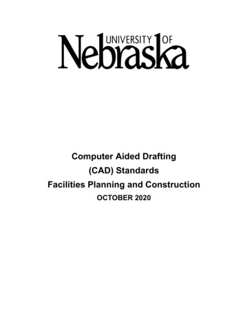
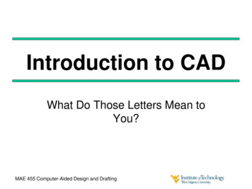
CADDWGeditorAnup GhoshComputer Aided Drafting – CAD
CADDWGeditorStatus BarA Information about the current command.B Cursor coordinates (x,y,z).C Layer name. Double-click to change layers.D Drawing color. By default, the color is BYLAYER. Double-click tochange colors.E Linetype. By default, the linetype is BYLAYER. Double-click tochange linetypes.F Snap setting. Double-click to toggle on or off.G Grid setting. Double-click to toggle on or off.H Orthogonal setting. Double-click to toggle on or off.I Entity snap setting. Double-click to select entity snaps.J Space mode setting. Double-click to select tile mode, model space,or paper space.K Digitizer mode. Double-click to toggle on or off.Anup GhoshComputer Aided Drafting – CAD
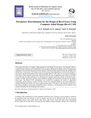
CADDWGeditor CommandsAnup GhoshComputer Aided Drafting – CAD
CADDWGeditor CommandsAnup GhoshComputer Aided Drafting – CAD
CADDWGeditor CommandsAnup GhoshComputer Aided Drafting – CAD
CADDWGeditor CommandsAnup GhoshComputer Aided Drafting – CAD
CADSetting UnitsSettings Drawing Settings drawing unitsCommand line unitsSetting AreaSettings Drawing LimitsCommand line limitsAnup GhoshComputer Aided Drafting – CAD
CADPointMethods to locate a point1Interactive:- Click a point on the screen. Use snap, grid,esnap for accuracy2Absolute Cartesian Co-ordinate:- X,Y3Relative Cartesian Co-ordinate:- @X,Y4Relative Polar Co-ordinate:- @distance angel5Direct Distance:- Move the courser in the direction and typethe distance on the command line. Use ortho or polartracking.Anup GhoshComputer Aided Drafting – CAD
CADPoint ExamplesAnup GhoshComputer Aided Drafting – CAD
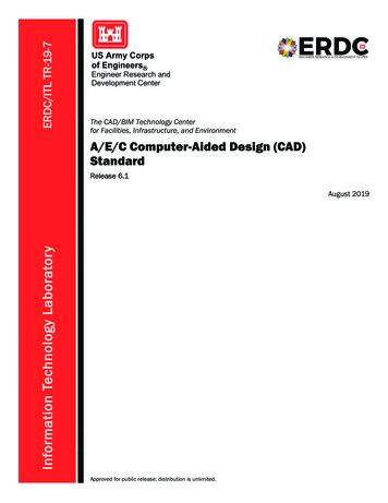
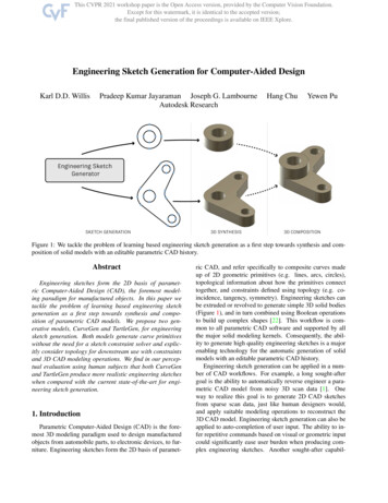
CADLineerase allPolar CoordinateExample -11Three o‘clock as the directionof the 00 angle2all other directions aredetermined counterclockwise8,7 enter3line enter52,2 enter42,2 enter6enter5@6 0 enter72,2 enter6@5 90 enter8@6,0 enter79@0,5 enter@7.8125 219.8056 enter orclose@-6,-5 enter810undo enter (to undo last step)1Type ’line’ and enter22,2 enter38,2 enter4Anup GhoshComputer Aided Drafting – CAD
CADLineerase allPolar CoordinateExample -11Three o‘clock as the directionof the 00 angle2all other directions aredetermined counterclockwise8,7 enter3line enter52,2 enter42,2 enter6enter5@6 0 enter72,2 enter6@5 90 enter8@6,0 enter79@0,5 enter@7.8125 219.8056 enter orclose@-6,-5 enter810undo enter (to undo last step)1Type ’line’ and enter22,2 enter38,2 enter4Anup GhoshComputer Aided Drafting – CAD
CADLineerase allPolar CoordinateExample -11Three o‘clock as the directionof the 00 angle2all other directions aredetermined counterclockwise8,7 enter3line enter52,2 enter42,2 enter6enter5@6 0 enter72,2 enter6@5 90 enter8@6,0 enter79@0,5 enter@7.8125 219.8056 enter orclose@-6,-5 enter810undo enter (to undo last step)1Type ’line’ and enter22,2 enter38,2 enter4Anup GhoshComputer Aided Drafting – CAD
CADLineMovie for illustrationAnup GhoshComputer Aided Drafting – CAD
CADDWGeditor CommandsImportant commandsline Draws straight lines of any length. You can specifythe two-dimensional or three-dimensional coordinatesfor the start or endpoints by entering thex,y,z-coordinates of the point.polyline Draws two-dimensional polylines (connected line andarc segments) with optional width and taper.spline Draws a free-form curve. To convert a polyline to aspline, use Polyline Edit .circle Draws a circle of any size. The default method ofdrawing a circle is by center point and radius, butthere are other methods you can use.arc Draws an arc of any size.Anup GhoshComputer Aided Drafting – CAD
CADDWGeditor CommandsImportant commandsfreehand Allows you to sketch by drawing short line or polylinesegments as quickly as you move the input device.text To enter text entity.dim Dimensions drawing entities in a variety of ways.vpoint Various view styles.erase To erase entities.break Splits an entity into two entities. You can split, orremove the ends from, lines, arcs, circles, polylines,infinite lines, rays, ellipses, splinesand donuts.Anup GhoshComputer Aided Drafting – CAD
CADDWGeditor CommandsImportant commandstrim Erases the portions of selected entities that cross aspecified boundary. You can trim lines and open twoand three-dimensional polylines, rays, arcs, andcircles. Entities that you can use as the cuttingentities are arcs, circles, lines, polylines, rays, infinitelines, and viewports in paper space.fillet Creates a fillet, or rounded corner, at the intersectionof two lines, rays, or infinite lines. If the entities youwant to fillet do not intersect, they are trimmed orextended until they can be filleted.Anup GhoshComputer Aided Drafting – CAD
CADDWGeditor CommandsImportant commandsextend Lengthens a line, an arc, a two-dimensional polyline,or a ray to meet another entity. You can usepolylines, arcs, circles, ellipses, infinite lines, lines,rays, splines, or viewports in paper space as boundingentities. When you use a two-dimensional polyline asa bounding entity, entities are extended to the centerline of the polyline.move Moves selected entities to another location in thesame drawing.scale Changes the scale of existing entities, either enlargingthem or reducing them proportionately in x, y, and zdirections. A scale factor greater than 1 enlarges theentities; a scale factor between 0 and 1 reduces them.Anup GhoshComputer Aided Drafting – CAD
CADDWGeditor CommandsImportant commandsrotate Rotates existing entities around a specified point.copy Draws a duplicate of the selected entities. You candraw multiple copies from a single selection, and youcan specify the base and displacement points. Theentities you select to copy are not moved from theiroriginal location. The entities you copy maintain allthe attributes (such as linetype, color, and layer) ofthe original entities.linetype Defines linetypes (sequences of alternating linesegments, dots, and spaces), loads them fromlibraries, and sets the current linetype.ltscale Defines linetypes (sequences of alternating linesegments, dots, and spaces), loads them fromlibraries, and sets the current linetype.Anup GhoshComputer Aided Drafting – CAD
CADDWGeditor CommandsImportant commandslimits Changes the Grid and Zoom ¿ All boundaries. Limitsare two-dimensional points representing the lower leftand upper right limits in the World CoordinateSystem (WCS).zoom Enlarges or reduces the display of the active drawing.To examine a drawing more closely, you can zoominto it. Doing this makes the drawing appear largeron the screen so you can see more detail. When youzoom in or out, you enlarge or reduce the display infive-percent increments.ellipse Draws ellipses and elliptical arcs. You can drawellipses or elliptical arcs dynamically by specifying themajor and minor axes or by specifying the centerpoint.Anup GhoshComputer Aided Drafting – CAD
CADDWGeditor CommandsImportant commandsrectangle Draws a rectangle. A rectangle is a polyline entity.polygon Draws polygons with a specified number of sides. Apolygon is created from a polyline entity. The defaultwidth of the polygon is specified with the PLINEWIDsystem variable, but you can change the width whenyou draw a polygon.donut Draws a filled circle or flat ring created as a polyline.You can use the system variable FILLMODE tospecify whether the donuts you create are filled. Toretain the fill, set the FILLMODE variable to 1; toremove the fill, set the FILLMODE variable to 0.mirror Moves or copies the reflected image of selectedentities about a line.Anup GhoshComputer Aided Drafting – CAD
CADDWGeditor CommandsImportant commandsoffset Creates a parallel or offset copy of curves and lines.units Displays the Prompt History window, which showseach of the measurement units and their respectivemeasurements for the selected entity. Select unitmeasurement options from the prompt box. To seethe choices for the prompts that follow, leave thePrompt History window turned on.ucsicon Turns the display of the UCS icon on or off, andcontrols where in the viewport the icon displays.ucs Defines or modifies the current user coordinatesystem. You can use the UCS to create a system forentering coordinates and planes and for viewingdrawings. This command defines the UCS inthree-dimensional space.Anup GhoshComputer Aided Drafting – CAD
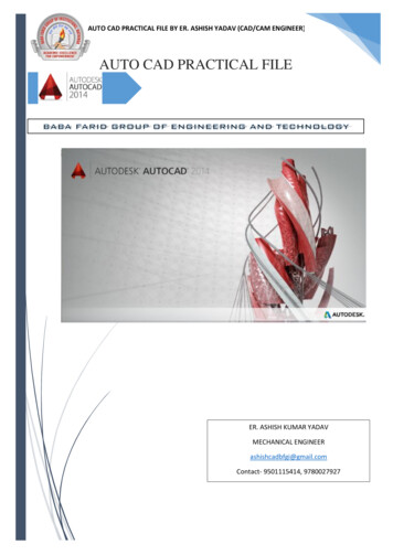
CADIsometric in 2DSuggestions1Use the “Relative Polar Co-ordinate Method” (@length, angle2Draw the square which encircle the circle.3Use four center method to complete the ellipse.Anup GhoshComputer Aided Drafting – CAD
CADEllipse in Isometric ViewSuggestions – 1Use the four center method.Suggestions – 21Use “Ellipse Center-Axes” method to draw an ellipse withcoinciding center of the diagonal of the rhombus.2Select the ellipse and open properties.3Change the “Axis Ratio” to 0.625 and ‘OK’4Drag the extreme end of the ellipse on the diagonal to make ittangent to the rhombus.5Remember to turn on the “ESNAP” with all options.6Use “Center, Axis and Angle” to draw partial ellipse.Anup GhoshComputer Aided Drafting – CAD
CADMovieMovie for illustrationAnup GhoshComputer Aided Drafting – CAD
CADAssignment Submission1Internet will remain on only for the last 30minbe collected through USB drives.OR files willa) Mail your submission toenggdrawingiitkgp@gmail.com2Subject line of the mail and file names should containa)b)c)d)3Session Code like 1cad / 2cad / 3cad / examcadRoll NumberProblem t your work and delete it from the computer.5No late submission will be accepted.Anup GhoshComputer Aided Drafting – CAD
Computer Aided Drafting is a process of preparing a drawing using a computer. In the eld of Mechanical Engineering, the drawing of machine components and layouts are prepared. In the eld of Civil Engineering, plans and layouts of the buildings are prepared. In the eld of Electrical Engineerin