Transcription
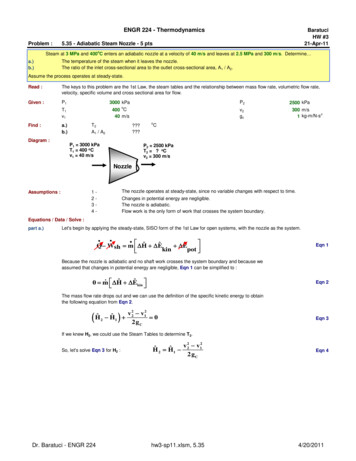
ENGR 224 - ThermodynamicsProblem :BaratuciHW #321-Apr-115.35 - Adiabatic Steam Nozzle - 5 ptsSteam at 3 MPa and 400oC enters an adiabatic nozzle at a velocity of 40 m/s and leaves at 2.5 MPa and 300 m/s. Determine a.)b.)The temperature of the steam when it leaves the nozzle.The ratio of the inlet cross-sectional area to the outlet cross-sectional area, A1 / A2.Assume the process operates at steady-state.Read :Given :Find :Diagram :The keys to this problem are the 1st Law, the steam tables and the relationship between mass flow rate, volumetric flow rate,velocity, specific volume and cross sectional area for flow.P13000 kPaP2T1v1o400 C40 m/sv2gcT2A1 / A2a.)b.)o?P1 3000 kPaT1 400 oCv1 40 m/s2500 kPa300 m/s21 kg-m/N-sCP2 2500 kPaT2 ? oCv2 300 m/sNozzleAssumptions :The nozzle operates at steady-state, since no variable changes with respect to time.1234-Changes in potential energy are negligible.The nozzle is adiabatic.Flow work is the only form of work that crosses the system boundary.Equations / Data / Solve :part a.)Let's begin by applying the steady-state, SISO form of the 1st Law for open systems, with the nozzle as the system. ˆ ˆˆQ Wsh m H E Ekinpot Eqn 1Because the nozzle is adiabatic and no shaft work crosses the system boundary and because weassumed that changes in potential energy are negligible, Eqn 1 can be simplified to : ˆ Eˆ 0 m Hkin Eqn 2The mass flow rate drops out and we can use the definition of the specific kinetic energy to obtainthe following equation from Eqn 2. Hˆ222ˆ v 2 v1 0 H12 gC Eqn 3If we knew H2, we could use the Steam Tables to determine T2.So, let's solve Eqn 3 for H2 :Dr. Baratuci - ENGR 22422ˆ Hˆ v 2 v1H212 gChw3-sp11.xlsm, 5.35Eqn 44/20/2011
Now, we can lookup H1 in the Steam Tables and plug values into Eqn 4 to evaluate H2 :Ekin,10.80 kJ/kgH13231.7 kJ/kgEkin,245.0 kJ/kgH23187.5 kJ/kgNow, because we know both P2 and H2, we can interpolate on the Steam Tables to determine T2.At P2 2500 kPa :Hsat vap2801.9 kJ/kgSince H2 Hsat vap, we can conclude that the steam leaving the nozzle is still a superheated vapor. So, we must interpolate inthe superheated steam table for 2.5 MPa.T (oC)At 2.5 MPa :part b.)300T2H (kJ/kg)2994.33187.5V (m3/kg)0.098937V24003231.70.12012T2381.4oCThe key to this part of the problem is the relationship between mass flow rate, volumetric flow rate, specific volume, crosssectional area for flow and the average fluid velocity. At steady-state, the mass flow rate is constant, so m1 m2. Vv AVv A m1 1 1 1 m 2 2 2 2ˆˆˆˆVVVV1122 Eqn 5We can now solve Eqn 5 for the cross-sectional area ratio, A1 / A2 :ˆA1 Vv 1 2ˆA 2 V2 v1Eqn 6We can evaluate the specific volume of the steam at both the nozzle inlet and outlet conditions :30.099379 m /kgV130.11618 m /kgV2Now, we can plug values into Eqn 6 to complete this problem.A1 / A2Verify :None of the assumptions made in this problem solution can be verified.Answers :a.)T2381b.)A1 / A26.42Dr. Baratuci - ENGR 2246.416oChw3-sp11.xlsm, 5.354/20/2011
ENGR 224 - ThermodynamicsProblem :BaratuciHW #321-Apr-115.54 - Adiabatic Gas Turbine - 5 ptsoArgon gas enters an adiabatic turbine at 900 kPa and 450 C with a velocity of 80 m/s and leaves at 150 kPa and a velocity of 150 m/s. The2inlet cross-sectional area is 60 cm . If the power output of the turbine is 250 kW, determine the exit temperature of the argon. The processoperates at steady-state and argon behaves as an ideal gas. The constant pressure specific heat of argon is 0.5203 kJ/kg-K.Read :The keys to this problem are the 1st Law and the Ideal gas EOS and the relationship between mass flow rate, volumetric flowrate, velocity, specific volume and cross sectional area for flow.Given :P1T1450723.15800.0060.5203v1A1CoPFind :Diagram :P2900 kPa?T2oCKm/s2mkJ/kg-Ko150 kPav2MWgcW 1 900 kPaT1 450 oCv1 80 m/sA1 60 cm2Wsh 250 kWQ 0 kWCP 0.5203 kJ/kg-KP2 150 kPaT2 ? oCv2 150 m/sA1 60 cm2Assumptions :12345-The turbine operates at steady-state.Change in potential energy is negligible.The turbine is adiabatic.Argon behaves as an ideal gas with constant specific heats.Flow work and shaft work are the only forms of work that cross thesystem boundary.Equations / Data / Solve :Apply the steady-state, SISO form of the 1st Law for open systems to the turbine. ˆ Eˆˆ Q W sh m Hkin Epot Eqn 1We can simplify Eqn 1 because the turbine is adiabatic and we have assumed that any change in potential energy is negligible.22 ˆ Eˆ m Hˆ Hˆ v 2 v1 W sh m Hk212g c Eqn 2We can express H in terms of the heat capacity and the temperature change using :T2ˆ dT Cˆ T T ˆ Hˆ Hˆ C H21PP21Eqn 3T1Combining Eqns 2 & 3 yields :2 2v 22 v 22v ˆ1 v1 ˆP TW shsh mT Wm CCTT 21P 21 2gc2 g c Eqn 4We can solve Eqn 4 for T2, as follows : 1 W sh v 22 v12 T2 T1 ˆ 2 gc CP m Eqn 5Dr. Baratuci - ChemE 260hw3-sp11.xlsm, 5.544/20/2011
So, we need to determine the mass flow rate. We can accomplish this because we are given the velocity and cross-sectionalarea for flow at the turbine inlet. m V1 v 1 A1 ˆˆVV11Eqn 6All we need to do now is determine the specific volume at the turbine inlet, V1.We can accomplish this using the ideal gas EOS, as follows.P1 V1 n R T1 mR T1MWSolving Eqn 7 for the specific volume yields :Eqn 7V̂1 V1R T1 m P1 MWEqn 8Plugging values into Eqns 5 & 6, in that order, yields :V130.16722 m /kgm2.8705 kg/sT2267.14 oCFinally, we can plug values back into Eqn 5 to complete this problem.Ekin,1Ekin,23.20 kJ/kg Ekin8.05 kJ/kg11.3 kJ/kgVerify :None of the assumptions made in this problem solution can be verified.Answers :T2Dr. Baratuci - ChemE 260267.1oChw3-sp11.xlsm, 5.544/20/2011
ENGR 224 - ThermodynamicsProblem :BaratuciHW #321-Apr-115.112 - Steam Flow in a HEX Tube - 5 ptsoSteam enters a long, horizontal pipe with an inlet diameter of D1 12 cm at 2 MPa and 300 C with a velocity of 3 m/s. Farther downstream, theconditions are 800 kPa and 250oC, and the diameter is D2 10 cm. Determine a.)The mass flow rate of the steamb.)The rate of heat transferRead :This problem is an application of the steady-state form of the 1st Law for open systems.Because both T & P are given at the inlet and outlet, the important properties specific enthalpy and specific volume can be directlydetermined from the steam tables, NIST Webbook or the TFT Plug-in.The keys to the problem are the relationships between mass flow rate, volumetric flow rate, velocity, specific volume, crosssectional area and pipe diameter.Given :State 11232000300DvPTFind :a.)mState 210800250cmm/skPaoC?kg/sb.)Q?kWDiagram :D1 12 cmP1 2000 kPaT1 300 oCAssumptions :D2 10 cmP2 800 kPaT2 250 oCThe pipe operates at steady-state, since no variable changes with respect to time.Changes in potential energy are negligible.Flow work is the only form of work that crosses the system boundary.123-Equations / Data / Solve :Since we were asked to determine the mass flow rate and the heat transfer rate and both of these variables appear in the 1st Lawfor open systems (like this pipe!), let's begin by writing the 1st Law for open systems. ˆ Eˆ Eˆ Q Wsh m Hkinpot Eqn 1Since no moving parts were mentioned in the problem statement, it safe to assume that no shaft work crosses the systemboundary. Since no elevation change was mentioned in the problem statement, it is safe to assume that changes in potentialenergy are negligible. As a result, Eqn 1 can be simplified to yield :22 ˆ Eˆ mˆ Hˆ v 2 v1 Q m HH kin 212 gC Dr. Baratuci - ChemE 260hw3-sp11.xlsm, 5.112Eqn 24/20/2011
Part a.) Eqn 2 shows that we need to determine ht e mass flow rate before we can use this form of the 1st Law to evaluate Q. So, itmakes sense to complete part (a) now.We can determine the mass flow rate based on the information given at the pipe inlet using the following equation. Eqn 3V v A crossm ˆˆVV The velocity was given, so we need to determine the cross-sectional area for flow, A1. If we assume the cross-sectional area forflow is circular, then we can determine A1 from : A1 D124Plugging valuesinto Eqn 4 yields :Eqn 4We can also evaluate the inlet volumetric flow rate if we want :2A1113.10cmA1V10.011310.03393m3m /sV10.12547m3/kgm0.2704kg/s2Next, we need to determine the specific volume at state 1. We canuse the steam tables, the NIST Webbook or the TFT Plug-in. Wecan do this because both P1 and T1 were given. I used the TFT Plugin to obtain :Chemical :WaterUnits :SI CNow, we can plug values back into Eqn 3 to determinem and complete this part of the problem.Part b.)Before we can use Eqn 4 to evaluate Q and complete this problem, we need to determine H1, H2 and v2.We can begin this part of the problem by using the steam tables, the NIST Webbook or the TFT Plug-in to evaluate H1 and H2.We can do this now because T & P were given for both the inlet and outlet states. I used the TFT Plug-in to obtain :3023.0H1H2kJ/kg2949.5kJ/kgLast, we need to determine v2. We can do this by solving Eqn 3, as follows. Eqn 5 ˆmVV2 v2 A2A2We can determine V2 using the steam tables, the NIST Webbook or the TFT Plug-in to evaluate H1 and H2. We can do this nowbecause T & P were given for the pipe effluent,state 2. I used the TFT Plug-in to obtain :V20.29314A278.54A2V20.007850.07927m3/kgNext, we can use Eqn 4 applied at the outlet of the pipe to determine A2.Plugging valuesinto Eqn 4 yields :Eqn 6 A 2 D224Now, we plug values into Eqn 5 to get :v2cm22mm3/s10.09 m/sWe can now complete this solution by plugging values into Eqn 2 to evaluate Q.gC 1kg-m/N-s2Verify :None of the assumptions made in this problem solution can be verified.Answers :a.)mDr. Baratuci - ChemE 2600.270kg/sb.)hw3-sp11.xlsm, 5.112Q-19.87kWQ-19.9kW4/20/2011
ENGR 224 - ThermodynamicsProblem :BaratuciHW #321-Apr-115.138 - Filling a Balloon with Helium - 10 ptsA balloon initially contains 40 m3 of helium gas at atmospheric conditions of 100 kPa and 17oC. The balloon is connected by a valve to a largereservoir that supplies helium gas at 125 kPa and 25oC. Now, the valve is opened and helium is alowed to enter the balloon until pressureequilibrium with the helium at the supply line is reached. The material of the balloon is such that its volume increases linearly with pressure. If noheat transfer takes place during this process, determine the final temperature of the helium in the balloon.Read :There are four keys to this problem. The first is that the He behaves as an ideal gas with constant heat capacities. This gives usa relatively simple relationship between P, V, T and moles or mass. It also simplifies the calculation of changes in U and H. Thesecond key is to apply the transient form of the 1st Law to this adiabatic process. Although there is no shaft work inthis process,there is boundary work, and because the balloon expands during the process, Wb 0. The third key is to make good use of theproperties of the balloon. Because P is linear with respect to volume, and we know the initial P and V and the final P, we canquickly determine the final volume. The final key to this problem is to recognize that you must choose a reference state so thatyou can evaluate U's and H's. Once you know how to use these four key aspects of this problem, the rest is just algebra !Given 5Find -KMW4.00g/moleT2?oCDiagram :Pin 125 kPaT1 25 oCV1 40 m3P1 100 kPaT1 17 oCAssumptions :V2 ? m3P2 125 kPaT2 ? oC1-Helium behaves as an ideal gas with constant CP and CV in this process.23-The process is adiabatic.The volume of He contained in the balloon increases linearly as the pressure within the balloonincreases.4-Uniform state: The state of the He in the balloon is uniform at any time during this process.5-Uniform flow: The properties and flow rate of the air entering the balloon are constant over the crosssectional area of the tube entering the balloon and the properties are also constant with respect totime. The flow rate into the balloon does not need to be constant in order to solve this problem.Dr. Baratuci - ChemE 260hw3-sp11.xlsm , 5.1384/20/2011
Equations / Data / Solve :Let's begin by writing the transient form of the 1st Law for uniform state, uniform flow processes:ˆ m Uˆˆˆm2U21 1 Q Wnon flow m in H in m out H outEqn 1This equation applies because the state within the system is indeed uniform and because the properties of the mass crossing thesystem boundary are constant. It is relevant because we know that U2 depends on T2 and T2 is what we are trying to determine.We can simplify Eqn 1 because the process is adiabatic, no mass leaves the system (the balloon) and there is no shaft work inthis process (only boundary work).ˆ m Uˆˆm2U21 1 Wb m in H inEqn 2Next, we can write the integral form of the transient mass balance or conservation of mass equation:m 2 m1 m in moutEqn 3Eqn 3 can be simplified because no mass leaves the balloon.m 2 m 1 m inEqn 4Next, we can apply the Ideal Gas EOS to the He in the balloon in both the initial and final states.PV nRT m1 P1 V1MWR T1mRTMWEqn 5m2 Eqn 6P2 V2MWR T2We can immediately evaluate m1, but we cannot evaluate m2because T2 is the unknown we are trying to determine.m1Eqn 76.633 kgNext, let's evaluate the boundary work done during this process from its definition.Wb V2 P dVEqn 8V1Because the volume of the balloon is linear with respect to pressure, we get the following equation for the boundary work.Wb P2 P1 V2 V1 2Eqn 9In order to evaluate Wb, we need to determine V2. We can do this by making use of the fact that volume is proportional pressure.P2 V2 P1 V1Solving Eqn 10 for V2 yields :V2 V1Eqn 10P2P1Eqn 11V2Now, we can plug V2 back into Eqn 9 to evaluate Wb :Dr. Baratuci - ChemE 260hw3-sp11.xlsm , 5.138Wb50 m31125 kJ4/20/2011
Now, we need to write equation for the U's and H's in Eqn 2 in terms of known and unknow T's.We can do this using the ideal gas heat capacities, as follows.T2 Cˆˆ Uˆ U2refoVdToVdTEqn 12TrefT1ˆ Uˆ U1ref CˆTrefˆ HˆH2ref Eqn 13T2 CˆoPdTTrefEqn 14Next, we must choose a reference state. It is often helpful to choose a state that actually exists in a problem to be the referencestate. So, I will choose U 0 for the initial state of He gas in the balloon.Tref290.15Pref100KkPaUref0kJ/kgNext, we need to determine Href from the definition of enthalpy.ˆˆˆHref U ref Pref VrefEqn 15ˆ R TrefPref VrefMWEqn 16But, Uref 0 and the He behaves as an ideal gas, therefore:Ĥ ref R TrefMWHrefEqn 17603.1 kJ/kgNow, because the heat capacities are constants, we can evaluate the integrals in Eqns 12 - 14.Û1 0 kJ / kgEqn 18ˆ o T T Ĥ in CPinrefEqn 20ˆ o T T Û 2 CV2refWe cannot evaluate U2 immediately becausewe do not know T2, but we can evaluate Hin.HinEqn 19644.6 kJ/kgNow, we can substitute Eqns 4, 6, 7, & 18 - 20 back into Eqn 2 to get : P2 V2 ˆo P2 V2 ˆMW CMW m1 H V T2 Tref Wb in R T2 R T2 Eqn 21The good news is that the only unknown left in Eqn 21 is T2. The bad news is that solving for T2 involves a bit of algebra. Here isone way to solve Eqn 21 for T2.Distribute T2 :ˆTref P2 V2 ˆo P2 V2 HˆMW CMW in m1 H Wb V 1 inT2 R R T2 Dr. Baratuci - ChemE 260hw3-sp11.xlsm , 5.138Eqn 224/20/2011
Collect the T2 terms on the right side of the equation : 1 P2 V2 P2 V2 ˆo ˆoˆˆMW CMW C V Wb m 1 H in V Tref H in T2 R R Plug in values :T2Verify :Eqn 23 P2 V2 ˆoˆMW C V Tref H inR T2 P2 V2 ˆoˆMW C V Wb m 1 H inR Solve for T2 :T2 Eqn 24 P2 V2 MW R 3006.98kg-K315.30Km29.54kg42.15oU278.35kJ/kgCThe only assumption that we can verify is the ideal gas assumption. We can verify this by determining the molar volume of He inthe initial, final and inlet states and comparing the results to 5 L/mole (He is a noble gas).V124.12 L/moleV220.97 L/moleVin19.83 L/moleSince the molar volume in all three states is significantly greater than 5 L/mole, the ideal gas assumption is valid.Answers :T2Dr. Baratuci - ChemE 26042.1 oChw3-sp11.xlsm , 5.1384/20/2011
ENGR 224 - ThermodynamicsProblem :BaratuciHW #321-Apr-115.142 - Charging a Cylinder with a Spring-Loaded Piston - 8 ptsAn adiabatic piston-and-cylinder device equipped with a spring maintains the pressure inside at 300 kPa when the volume is zero and 3000kPa when the volume is 5 m3. The device is connected to a steam line maintained at 1500 kPa and 200oC and initially the volume is zero.Determine the final temperature (and quality if appropriate) when the valve is opened and steam in the line is allowed to enter the cylinderuntil the pressure inside matches the pressure in the line. Also determine the total work produced during this adiabatic filling process.Read :This problem is a transient mass and energy balance on a uniform-state, uniform-flow process.The twist is that boundary work is done against the spring as the cylinder fills with steam and the pressure rises.The main complication is that in the final state, the temperature is unknown (T2) and both the final specific volume and the finalinternal energy depend on T2. This is a significant complication. It makes the soution of this problem iterative. This iterativesolution is easily accomplished using the TFT Plug-in for thermodynamic properties along with the Solver add-in for excel. Ifeither or both of these tools is unavailable, the solution becomes one of trial and error. The NIST Webbook can make trialand error a bit less painful compared to suing paper steam tables.Given :V1TinPin P202001500T2?Find :m3CkPaooSpringPropertiesP (kPa)3003000V (m3)05CDiagram :V1 0 m3P1 300 kPaAssumptions :V2 ? m3P2 1500 kPa1-The process is a quasi-equilibrium process. This allows us to calculate the boundary work doneusing the integral of P dV.2-The spring is a linear spring. The process path is a straight line on a PV Diagram.Uniform state: The state of the steam in the cylinder is uniform at any time during this process.34-Dr. Baratuci - ChemE 260Uniform flow: The properties and flow rate of the steam entering the cylinder are constant over thecross-sectional area of the pipe entering the cylinder and the properties are also constant withrespect to time. The flow rate into the cylinder does not need to be constant in order to solve thisproblem.hw3-sp11.xlsm, 5.1424/20/2011
Equations / Data / Solve :The filling of the cylinder is a transient process because the mass of water inside the cylinder increases as a function of time.So, let's begin by writing the transient form of the 1st Law as it applies to systems undergoing uniform flow and uniform stateprocesses.ˆ m Uˆˆˆm2U21 1 Q Wnon flow m in H in m out H outEqn 1In this problem the only form of non-flow work is boundary work done against the spring pushing on the back of the piston.Eqn 1 can be further simplified because the cylinder is initially empty (m1 0), the process is adiabatic (Q 0) and there is noflow out of the balloon (mout 0). The resulting form of the 1st Law is :ˆ W m Hˆm2U2bininEqn 2The transient mass balance or conservation of mass equation for this process is:m 2 m1 m in m outEqn 3Eqn 3 can be simplified because there is initially no mass inside the cylinder (m1 0) and no mass flows out of the cylinder(mout 0).m 2 m inEqn 4ˆ W m Hˆm2U2b2inWe can use Eqn 4 to eliminate min from Eqn 2 :Eqn 5We need to solve Eqn 5 for U2 because if we know the value of U2, we can use thermodynamic data to determine T2.So, next, let's try to evaluate the boundary work. Because we have assumed the process to be quasi-equilibrium, we canevaluate Wb using :Wb V2 P dVEqn 6V1Because the spring is linear, the process path is linear on a PV Diagram and Eqn 6 can be simplified to obtain :Wb P2 P1 V2 V1 2Eqn 7The characteristics of the spring given in the problem statement lead us to conclude that P1 300 kPa when the cylinderbegins to fill with steam and the pressure in the cylinder increases linearly with pressure until it reaches P2 1500 kPa.The linear characteristics of the spring also allow us to conclude that V1 0 m3 and that V2 can be determined by linearinterpolation, as follows.V (m3)0V25P (kPa)30015003000Now, we can plug values into Eqn 7 to evaluate Wb :V22.222m3Wb2000kJThe next step in resolving Eqn 5 is to evaluate Hin. We can do this using the steam tables, the NIST Webbook or the TFTPlug-in. I used the TFT plug-in to obtain :Chemical :Units :WaterSI CHinNow, let's try to determine m2. We know that mass and volume are related by :m2 2796.3V2V̂2kJ/kgEqn 8This introduces a new level of complexity into Eqn 5 because the specific volume in state 2 depends on T2 ! V2 ˆ V2Dr. Baratuci - ChemE 260 ˆ W V2 U2b Vˆ 2 ˆ Hin hw3-sp11.xlsm, 5.142Eqn 94/20/2011
ˆ UˆWb m 2 Hin2Let's rearrange Eqn 9, as follows : Eqn 10The problem is that because both specific U2 and specific V2 depend on T2, Eqn 10 must be solved iteratively !This problem can be solved very quickly using the TFT Plug-in and the "Solver" add-in for Excel, as follows.T2 (oC)210V2 (m3/kg) U2 (kJ/kg)0.136602618.4m2 (kg)16.268 ˆ Uˆm2 Hin2 ˆ Uˆerror Wb m 2 Hin22895.0 895.0Now, use Solver to minimize the /error/ by changing T2. The results are shown below.233.860.145942665.02000.015.2270.0If you do not use the TFT Plug-in or yu do not use Solver, you can create a table by guessing T2 repeatedly until Eqn 10 issatisfied. Such a table is shown below.T2 (oC)210220230240235231232233234233.5233.75233.86V2 (m3/kg) U2 0.145942665.0m2 6215.22215.24215.23215.227 ˆ Uˆm2 Hin2 ˆ Uˆerror Wb m 2 .21995.22012.22003.72000.0The result is :None of the assumptions made in this problem solution can be verified.Answers :T2233.9 2Verify :Dr. Baratuci - ChemE 260 233.9oCoChw3-sp11.xlsm, 5.1424/20/2011
ENGR 224 - ThermodynamicsProblem :BaratuciHW #321-Apr-11WB-1 - Effluent Pressure in a Non-Adiabatic Steam Diffuser - 5 ptsoSteam enters a diffuser at a pressure of 14.7 psia, a temperature of 300 F and a velocity of 500 ft/s. Steam exits the diffuser as a saturatedvapor with negligible kinetic energy. Heat transfer occurs from the steam to the surroundings at a rate of 19.59 Btu/lbm of flowing steam.Neglecting potential energy effects, determine the exit pressure in psia. Assume the diffuser operates at steady-state.Read :This is a straightforward application of the 1st Law to a non-adiabatic diffuser operating at steady-state with negligible changesin potential energy.The keys to this probelm are the 1st Law and the relationship between mass flow rate, volumetric flow rate, velocity, specificvolume and cross sectional area for flow.Given :P1Find :P2Diagram :x214.7 psiao300 F500 ft/s232.174 lbm-ft/lbf-sT1v1gc?v2Q/m Epot1 Btu1 kg vap/kg0 ft/s-19.59 Btu.lbm0 kJ/kg778.17 ft-lbfpsiaP1 14.7 psiav1 500 ft/sT1 300 oFP2 ? psiax2 1 lbm vap/lbmv2 0 ft/sDiffuserAssumptions :123-The diffuser operates at steady-state.Changes in potential energy are negligible.Flow work is the only form of work that crosses the system boundary.Equations / Data / Solve :Apply the steady-state, SISO form of the 1st Law for open systems to the diffuser. ˆ Eˆ Eˆ Q Wsh m Hkinpot Eqn 1Because no shaft work crosses the system boundary and because we assumed that changes in potential energy arenegligible, Eqn 1 can be simplified to : ˆ Eˆ m Hˆˆˆ Q m Hkin 2 H1 Ekin Where : Êkin v 22 v122 gCEqn 2Eqn 3If we knew the value of H2, we could determine P2 because we know that the effluent is saturated vapor, x2 1.0. Toward thatend, we can solve Eqn 1 for the unknown H2. ˆ Hˆ Q EˆH21kin mDr. Baratuci - ChemE 260Eqn 4hw3-sp11.xlsm, WB-14/20/2011
Because we know both T1 and P1, we can lookup H1 in the Steam Tables.We can determine the phase of the feed stream by comparing T1 to Tsat at P1 14.7 psia.o300 Fo211.95 FT1TsatSince T1 Tsat, we can conclude that the feed is a superheated vapor.In the superheated steam table for 14.7 psia, we find the value of H1.H11192.7 Btu/lbmNext, we can plug values into Eqn 3 because we know v1 and we have assumed that the effluent kinetic energy is negligible.3885 ft-lbf/lbm4.993 Btu/lbmEkin,1Ekin,2Now, we can use Eqn 4 to evaluate H2. Ekin0.0 kJ/kg0.0 Btu/lbm-4.993 Btu/lbmH21178.1 Btu/lbmNow, because we know both x2 1 and the value of H2, we can interpolate on the saturated vapor column of the saturationpressure table to determine P2.P (psia)60P2H (Btu/lbm)651179.41177.81178.1P2Verify :None of the assumptions made in this problem solution can be verified.Answers :P2Dr. Baratuci - ChemE 26060.95 psia60.9 psiahw3-sp11.xlsm, WB-14/20/2011
ENGR 224 - ThermodynamicsProblem :BaratuciHW #321-Apr-11WB-2 - Steady-State, Polytropic Air Compressor - 5 ptsAir enters a compressor at steady-state with a pressure of 14.7 psia, a temperature of 70 F, and a volumetric flow rate of 500 ft3/min. The airvelocity in the exit pipe is 700 ft/s and the exit pressure is 120 psia. If each unit mass of air passing through the compressor undergoes aprocess described by PV1.34 constant, determine the exit temperature, in oF, and the diameter of the exit pipe in inches.Read :Given :P1T1T2?120 psiaov21 ft2 moleoD2?in70 F529.67 oR3500 ft /s1.34V1 Find :P214.7 psiaFDiagram :P2 120 psiaT2 ? oFv2 700 ft/sD2 ? inCompressorP1 14.7 psiaT1 70 oFV1 500 ft3/minAssumptions :12345-The compressor operates at steady-state.Changes in potential energy are negligible.Shaft work and flow work are the only forms of work that cross the system boundary.The cross-sectional area for flow in the exit pipe is circular.Air behaves as an ideal gas throughout the process. This assumption will be verified.Equations / Data / Solve :Th e key to this problem is that the mass flow rate is the same at the outlet as it is at the inlet. So, let's begin by seeing if wehave enough information about the compressor feed to evaluate the mass flow rate. m V1Eqn 1V̂1The volumetric flow rate of the feed is given, so we need to determine the specific volume of the feed. We can accomplish thisby applying the Ideal Gas EOS.P1 V1 n R T1 Solving Eqn 2 for the specific volume yields :V̂1 Plugging values into Eqns 3 & 1 yields :mR T1MWEqn 2V1R T1 m P1 MWEqn 3V1m13.348 ft3/lbm0.6243 lbm/sNow that we know the mass flow rate, we can use it to determine the diameter of the exit pipe, as follows.Begin by solving Eqn 1 for the volumetric flow rate of stream 2. ˆV2 m V2Eqn 4
The key to determining the specific volume of the effluent is the polytropic process path: P V1.34 constant.Both the feed and the inlet states lie on this process path. Therefore:ˆ 1.34 constant P Vˆ 1.34P1 V122Eqn 5æ öˆ Vˆ çç P1 V21ççè P2 øEqn 61/ 1.34We can now solve Eqn 5 for V2 :Next, we can use the volumetric flow rate and the given velocity to determine the cross-sectional area of the exit pipe, A2 : A2 V2v2Assuming the exit pipe is circular in cross-section :A2 2D24Solving Eqn 8 for D2 yields :D2 V 2 v2 A2Eqn 6Eqn 7Eqn 84A2 Eqn 9Now, we can plug values into Eqns 6, 4, 7 & 9 to complete this part of the problem.2.786 ft3/lbm31.739 ft /sV2V2A2D220.002484 ft0.0562 ftD20.675inWe can now apply the Ideal gas EOS to determine T2 because we know P2 and V2. Apply Eqn 3 to the compressor effluent andsolve for T2, as follows :V̂2 R T2P2 MWEqn 10Plugging values into Eqn 11 yields :T2 ˆP2 V2R / MWT2T2Verify :We can test the Ideal Gas assumption by determiningthe molar volume of the feed and the effluent from :Plugging values into Eqn 12 yields :Eqn 11902.35 oR442.68oFEqn 12 Vˆ MWVV1V23386.7 ft /lbmole380.70 ft /lbmoleThe rule of thumb is that a gas be considered to be an ideal gas, to an accuracy of 2 significant figures, if the molar volume isgreater than 350 ft3/lbmole. So, it is very reasonable to treat the compressor feed as an ideal gas. What about the compressoreffluent ? For diatomic and noble gases the molar volume must only be greater than or equal to 70 ft3/lbmole. Air cansometimes be treated as a diatomic gas since its main consitituents are O 2 and N2. To the extent that this rule can be applied toair, the ideal gas assumption is valid for the compressor effluent.Answers :T2443oFD20.675in
ENGR 224 - ThermodynamicsBaratuciHW #321-Apr-11Problem : WB-3 - Analysis of a Two-Stage, Adiabatic Turbine - 6 ptsA well-insulated two-stage turbine operating at steady-state is shown in the diagram. Steam enters at 3 MPa and 400oC with a volumetricflow rate of 85 m3/min. Some steam is extracted from the turbine at a pressure of 0.5 MPa and a temperature of 180oC. The rest expandsto a pressure of 6 kPa and a quality of 90%. The total power developed by the turbine is 11,400 kW. Changes in kinetic and potentialenergies are negligible. Determine:a.)The mass flow rate of the steam at each of the twoexits.P1 3000 kPaT1 400 oCV1 85 m3/minb.)The diameter in meters of the duct through which the0.5 MPa steam is extracted if the velocity there is 20m/s.P2 500 kPaT2 180 oCP4 500 kPaT4 180 oCRead :P3 500 kPaT3 180 oCP5 6 kPax5 0.9 kg vap/kgThe key to this problem is the splitter. It is just like a tee in a pipe. So, the properties of streams 2, 3 & 4 are the same.Apply the 1st Law to the HP Turbine and determine Wsh,HP. The remaining work is Wsh,LP. Apply the 1st Law to the LPTurbine to determine m5. Use a mas
The keys to this problem are the 1st Law, the steam tables and the relationship between mass flow rate, volumetric flow rate, velocity, specific volume and cross sectional area for flow. Steam at 3 MPa and 400oC enters an adiabatic nozzle at a velocity of 40 m/s and leaves at 2.5 MPa and 300 m/s. Determine
