Transcription
A Multi-Robot Search Using LEGO Mindstorms– An Embedded Software Design ProjectPaula HerberVerena KlösUniversity of PotsdamAugust-Bebel-Str. 89, 14482 PotsdamPotsdam, GermanyTechnische Universität BerlinErnst-Reuter-Platz 7, 10587 BerlinBerlin, berlin.deABSTRACT1.Embedded software is concurrent, real-time dependent, typically networked, must meet strict resource and high quality requirements, and often runs on cheap hardware. Altogether, this makes the education of embedded softwaredesigners a difficult challenge. In this paper, we present anembedded software design project, where students have todevelop a multi-robot search using Lego mindstorms. Themain idea is to confront the students with all the spitesthat are typically present in embedded systems, while atthe same time giving them an algorithmically non-trivialproblem to solve. To this end, we let the students use abio-inspired search algorithm (particle-swarm optimization)to detect survivors (led by cries for help) in an unknown disaster zone using a number of Lego Mindstorm robots. Wehave executed this project simultaneously at the Universityof Potsdam and TU Berlin and discuss results and evaluations. We think that this project is very well suited for theeducation of embedded software engineers.The amount of embedded software is steadily increasing.In [4], the authors state that the annual growth of the volume of embedded software varies between 10 and 20 %.Embedded software engineers have to cope with this growing complexity. At the same time, the systems are oftennetworked and heavily interconnected. They typically consist of simple and often imperfect hardware, which imposesstrict resource constraints, and, due to the interaction withthe physical environment, the software must be designedto cope with real-time and concurrency. To meet all the requirements, embedded software designers need to know theirhardware, and they need to cope with both functional andnon-functional requirements.The steadily increasing complexity of embedded softwaretogether with the multi-demands in interdisciplinary applications makes the education of embedded software engineersa difficult challenge. Embedded software engineers need tobe able to apply software engineering methods, they needto know how to cope with the perils of cheap and unreliable hardware, and they need to be able to work togetherwith experts from various application fields (and/or becomeexperts in the application field themselves).In this paper, we propose an embedded software designproject, which we have designed to target all of the issuesmentioned above. We are confident that this project canprovide a valuable contribution to the education of embedded software engineers. The main idea is to confront thestudents with all the spites that are typically present inembedded systems (like imprecise sensors, limited resourcesand concurrency) and to give them an algorithmically nontrivial problem to solve. We let the students use a bioinspired search algorithm (particle-swarm optimization) toexplore an unknown disaster zone and to detect survivors(modeled as a non-linear sound source) using a number ofLego Mindstorm robots. Among the requirements is collision avoidance, the ability to cope with an unstable bluetooth connection, and the demand for an emergency modewhere all robots have to return to their bases on the shortestpossible path.We have executed this project simultaneously at the University of Potsdam and TU Berlin and discuss results andevaluations. Our project is designed for students in the finalyear of their Bachelor or in the first year of their Master.A prerequisite for the successful execution of this project isthat the students have already completed some backgroundcourses on software engineering and on embedded systems.They should have some knowledge about typical charac-Categories and Subject DescriptorsC.3 [Computer Systems Organization]: Special-purposeand application-based systems—Real-time and Embedded Systems; K.3.2 [Computing Milieux]: Computers and Education—Computer and Information Science EducationGeneral TermsDesignKeywordsEducation, Embedded Systems, Multi-Robot Search Paula Herber and Verena Klös 2016. This is a minor revision ofthe work published in Proceedings of the WESE’15: Workshop on Embedded and Cyber-Physical Systems Education, Article No. 2, yright is held by the authors. Publication rights licensed to ACM.INTRODUCTION
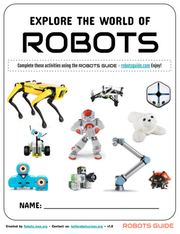
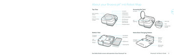
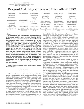
teristics of embedded systems, like concurrency, real-time,limited resources, and non-functional requirements. Theyshould also have learned and practiced (formal) specification and modeling techniques for embedded systems, e.g.timed automata or Statecharts, and temporal logics. Theyshould be familiar with programming techniques for concurrent systems (tasks and processes, inter-process communication, scheduling, shared resources), and, finally, they shouldhave some experience in C programming.We start the semester with a few introductory lectures andexercises to bring the students to the same level of knowledge and to equip them with the necessary basic knowledgeon embedded systems, the employed software and projectmanagement. The project work itself starts two weeks afterthe beginning of the semester. Then, the weekly lectures arereplaced by oral milestone presentations about the progressin each project group every three weeks. The semester isclosed with a final presentation at the end of the semesterand oral exams, where the students explain and defend theircontributions to the project. The overall project is worth 9credit points (ETCS).The remainder of this paper is structured as follows: first,we give some background information on Lego Mindstorms,the real-time operating system nxtOSEK, UPPAAL timedautomata, and particle swarm optimization. Then, we presentour embedded software design project, with a focus on theproject task and project organization and management. InSection 4, we discuss the technical challenges and results ofthe project. We briefly discuss our evaluation of the projectin Section 5, and conclude in Section 6.2.PRELIMINARIESIn this section, we introduce the preliminaries that arenecessary to understand the remainder of this paper. Wefirst give a brief overview over the Lego Mindstorms hardware and the real-time operating system nxtOSEK for theLego Mindstorms programmable NXT. Then, we briefly introduce UPPAAL timed automata, a formal modeling language for real-time systems. Finally, we provide a short description of the general ideas of particle swarm optimization(PSO).2.1Lego MindstormsThe Lego Mindstorms NXT 2.0 kit was released by Lego2009 and consists of a set of Lego components to build customizable, programmable robots. It includes a set of modular sensors and actuators, in particular 3 servo motors, andultrasonic, sound, touch, and light sensors. The main component is the NXT intelligent brick, which features a 32-bitAtmel main microcontroller with 256 KB flash memory and64 KB RAM, a 100x64 pixel LCD screen, four sensor and 3actuator ports, a USB port and Bluetooth V2.0. The NXTintelligent brick together with its sensors and actuators isshown in Figure 1.Lego Mindstorms have been shown to excite a high levelof interest among students [19] and have been used in manycourses ranging from basic computer engineering courses [9,10, 12] to more advanced control systems [7, 5]. In oursetting, they provide an ideal target architecture, as theyare cheap (approx. 300 per education kit), easy to build,and provide modular hardware including sensors and actuators. At the same time, they can be equipped with asmall real-time operating system (e.g. nxtOSEK), have lim-Figure 1: Lego Mindstorm NXTited resources (memory, energy, processing power), and thehardware is neither reliable nor precise. Finally, the LegoMindstorms NXT is programmable in many programminglanguages, ranging from various C dialects over high-levellanguages like Python, Ada, and Java to graphical languageslike MATLAB Simulink. In our project, we chose a concurrent version of classical C as this is still the most widelyspread language in embedded systems.2.2nxtOSEKThe real-time operating system nxtOSEK [13] consists oftwo main components: a device API (leJOS [11]) that enables convenient access for NXT sensors, actuators and otherexternal devices, and a standard software architecture forembedded operating systems in automotive systems, TOPPERS/ATK OSEK [18], which provides real-time multitasking features according to the OSEK standard. nxtOSEK isfocused on real-time control applications and provides preemptive periodical and event-driven task scheduling.2.3UPPAAL Timed AutomataTimed automata (TA) [1] are finite-state machines extended with clocks, where clock conditions are used to modeltime-dependent behavior. A TA contains a set of locationsconnected by directed edges. Two types of clock constraintsare used to model time-dependent behavior: Invariants areassigned to locations and enforce progress by restricting thetime the automaton can stay in this location. Guards areassigned to edges and enable progress only if they evaluate to true. Networks of TA are used to model concurrentprocesses, which are executed with an interleaving semantics and synchronize on channels. UPPAAL [2] is a toolsuite for modeling, simulation, and verification of TA. TheUPPAAL modeling language extends TA by bounded integer variables, binary and broadcast channels, and urgentand committed locations. Binary channels enable a blockingsynchronization between two processes, whereas broadcastchannels enable non-blocking synchronization between onesender and arbitrarily many receivers. Urgent and committed locations are used to model locations where no time maypass. Furthermore, leaving a committed location has priority over non-committed locations. The formal semantics ofUPPAAL timed automata (UTA) is given in [2].UPPAAL timed automata can be verified using the UPPAAL model checker, which supports requirements specifications that are defined in a subset of the computation tree
logic CTL. The UPPAAL model checker explores all pathesof a given timed automata model to check whether a givenformula is true. As all state-of-the-art model checking tools,it also provides a counter-example if a property is not satisfied on all pathes. This counter-example can also be used todemonstrate the reachability of a certain path. In particular,UPPAAL also provides a shortest path option, which can beused to compute the shortest possible path that witnessesthe reachability of a certain property. In [17], the authorshave shown how UPPAAL and the shortest path option canbe used to compute the shortest pathes for a number of mobile robots on a given map with static obstacles.2.4Particle Swarm OptimizationIn [14, 15], Pugh and Martinoli presented a concept tosolve the multi-robot search problem by using particle swarmoptimization. Particle swarm optimization (PSO) as an optimization technique was developed by Kennedy and Eberhart [8]. The main idea is to model a set of potential solutions for a given problem as a swarm of particles searching ina virtual space for good solutions. The method was inspiredby the movement of flocking birds and their interactions withtheir neighbors.The PSO algorithm works as follows [14]: Every particle inthe swarm begins with a random position xi and (possibly)randomized velocity vi in an n-dimensional search space,where xi,j represents the location of particle i in the j-thdimension of the search space. Each particle remembersat which position it achieved the best result so far x i,j , andwhich particle achieved the best overall position in its neighborhood x i0 ,j . Then, at each step, a PSO algorithm executesthe following equations:vi,j w · vi,j wp · rand() · (x i,j xi,j )xi,j wn · rand() · (x i0 ,j xi,j ) xi,j vi,jWhere wp is the weight given to the previous best locationof the current particle and wn is the weight given to the previous best location of the particle neighborhood, and rand()yields a uniformly-distributed random value in [0, 1]. ThePSO-inspired multi-robot search presented in [14, 15] usesa one-to-one matching between particles in the PSO swarmand robots in the multi-robot system.3.EMBEDDED SOFTWAREDESIGN PROJECTThe aim of our embedded software design project is toteach the students to work together in a team on a complexembedded software design. Besides the embedded softwaredesign task itself, our goal is that they gain experience inproject management and organization. In particular, theyshould learn how to divide a comparatively large design taskinto smaller tasks, and how to communicate between multiple teams that are working on subsystems, which are laterintegrated into one system. The system integration is one ofthe main challenges in embedded system design. This hasseveral reasons: Subsystems are designed by experts of various domains.The behavior of one subsystem is only partially understood by the designers of another subsystem. All subsystems are concurrent. Thus, the overall system behavior is hard to predict. Processing and memory resources are limited. Resource access must be managed, and the overall resource consumption must be controlled. Some processes are real-time dependent. Their correcttiming behavior must still be ensured if their executionis interleaved with other processes. All sensors, actuators, and communication devices mustbe assumed to be unreliable and inaccurate. As a consequence, subsystems can not always rely on results oranswers from other subsystems.In the following subsections, we will first define the projecttask and briefly summarize the corresponding requirementsdefinition, which we have given to the students. Then, wewill briefly present our technical equipment and support. After that, we will discuss our project organization and projectmanagement. In the next section (Section 4), we will presentsome more details about the project execution itself, including exemplified design decisions, to give an impression ofthe technical challenges and detailed content of the projectwork.3.1Project TaskThe aim of the project is to implement a multi-robotsearch in an unknown environment using a number of LegoMindstorms. The goal of the search is a non-linear soundsource. The motivating real-world application is the detection and localization of survivors in a disaster zone, led bycries for help. In such scenarios, the use of autonomousmobile robots renders the use of human search personal unnecessary and thus may save lives and cost, in particularif the disaster zone is still considered unsafe, as is the casein the aftermath of earthquakes or flooding. A swarm ofsimple and cheap robots has the further advantage that itis tolerant against failures of a number of single robots, canexplore a given area quickly and scales well for larger areas.Project Goal.The aim of the project is to design a swarm of at leastthree mobile robots, which localize a sound source usingsound sensors. All movements must be planned and carriedout by local rules on each robot, e.g. by particle swarmoptimization as presented in [14, 15]. The swarm may communicate via bluetooth, but has to cope with unstable andtemporarily unavailable bluetooth connections. Collisionsmust be avoided at all times and in all cases. At any time,a central control element may recall all robots to their basestations using an emergency mode. In this mode, the shortest path to return all robots to their base station is centrallycomputed and communicated to each robot, for example byusing the UPPAAL based approach presented in [17]. In theemergency mode, sound and ultrasonic sensors are switchedoff, so it is important that the algorithm to compute thepathes back to the base station for each robot is provablycollision free. This can be ensured by using the UPPAALmodel checker for the computation of the shortest path. Ifthe sound source is detected, the robots should indicate this
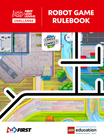
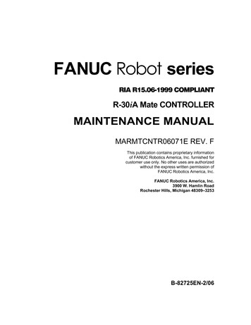
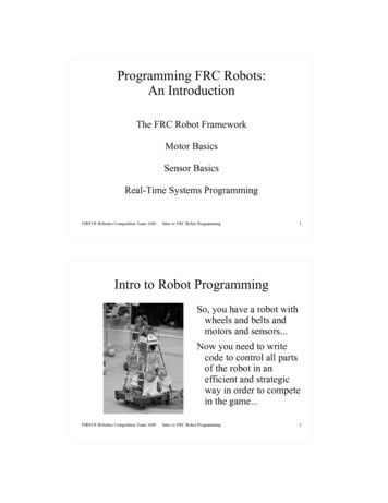
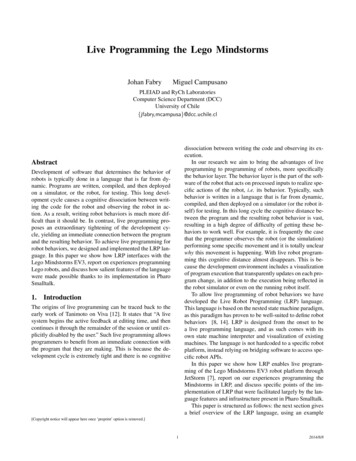
Each solution must cope with unstable bluetooth connections.Note that we give the complete project goal and all requirements to the students at the beginning of the semester.No requirements are changed during the semester, as thiswould go beyond the scope of one semester.3.2Technical Equipment and SupportFor the execution of this project, it is most advantageousto have a project room that is solely dedicated for the useof the project during the whole semester. In our case, theproject rooms are equipped with a number of PCs runningUbuntu where we pre-installed the following software: The GNU ARM cross compiler from the Gnu CompilerCollection (GCC) [6], which supports the ARM7 CPUinside the NXT.Figure 2: 2D search space John Hansen’s NeXTTool from the Programmable BrickUtilities repository [3], which can be used to communicate with the NXTs via USB & Bluetooth (and thusalso enables program upload).with a sound signal and broadcast the information to allother swarm elements and to the central control.Simplifications.To enable our students to solve the project task withinone semester, we use the following simplifications of thisscenario: The nxtOSEK real-time operating system, which canbe compiled together with user-defined C or C codeinto nxtOSEK applications for NXTs. The robots move in a 2-dimensional search space, asshown in Figure 2.As building equipment for the mobile robots, we provideour students with five boxes of the 9797 LEGO Mindstorms Education Base Set together with five boxes ofthe 9695 LEGO Mindstorms Education Resource Set,plus five additional lightsensors.As a project management platform, we have set up a Redmine server together with a subversion (SVN) repository.The former is used by the students as a project planningtool, ticketing system, and online platform for informationexchange (discussion forums, document upload). The latteris used as a versioning and revision control system for shareddevelopment of the code base developed in the project. The search space is rectangular and its size is known. The search space is marked by a (physically detectable)grid, which enables orientation and positioning of therobots. The location of the sound source is as also marked onthe grid to simplify the physical identification of thegoal. Obstacles are cubes which have the same edge lengthas one field in the grid and are aligned to the grid. A PC may be used as a hub for the communicationbetween the robots, and to build and distribute a common map from the information collected by all robots.Additional Requirements.Besides the project goals defined above, we give the students the following additional requirements:3.3The challenges of system integration in embedded software design projects can only be met if the overall projectis properly managed. In students’ projects, the studentshave to self-manage their project work, typically in a nonhierarchical fashion.1 In our embedded software design project,we build groups of 8-9 students. Each group has to namepersons that are responsible for:1. requirements, change, and risk management (definition and evolution of requirements, identification andcommunication of changes and risks ) The hardware of the robots is identical for each groupand is developed by all groups together.2. project planning (work breakdown structure, scheduling, milestones) All robots of one group run the same software. All robots start at a defined base station.3. technical project management (interface definition, interprocess communication, communication between teamsworking on different subsystems, system integration) The robots must never collide with each other or withobstacles.4. quality assurance (coding standards, review strategies,verification and test plans) The resulting map should be shown on a PC. The performance of each solution is measured by thetime needed to find the sound source and by the qualityand robustness of the solution.Project Organization1A hierarchical project management would not have thesame learning outcome for all the participants, and is difficult to deploy within groups of students, for many reasons.
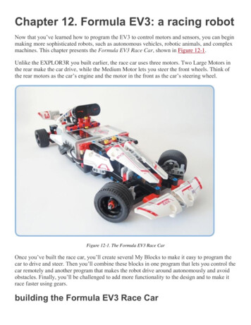
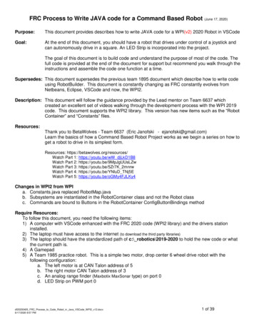
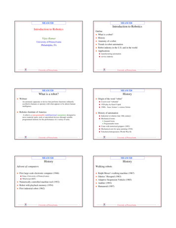
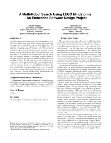
MilestoneMS 105/05Multi-RobotSearchRobot designPSOMotor & SensorControlEmergencyModeCommunicationHubMS 205/26Figure 3: Work Breakdown StructureMS 306/16It is important that each student assumes one of these responsibilities. This ensures that all of the participants takepart in the project management. Furthermore, it results inthe fact that 2(-3) students are responsible for each role, introducing yet another type of teamwork in the project. Thestudents that are assigned with the above responsibilitiesare in charge of their role during the whole project, in addition to the later assigned design tasks. The definition ofthe roles is important to make sure that the project groupsself-organize their work and that there are cleary definedcontact persons for each problem scope.3.4Project ManagementBesides the experience in embedded software design, thestudents should also gain experience in project managementand organization. In large and interdisciplinary projectsit is important to divide a large design task into smallertasks, and to communicate between multiple teams that areworking on subsystems, which are later integrated into onesystem. Therefore, the students have to develop their ownproject plan consisting of a work breakdown structure, deliverables for four predefined milestones and a gantt chartwhich shows the project schedule, the schedule of human resources and the current progress. Depending on their projectplan they divide their group into teams and define workpackages and interfaces for each team. Besides a weeklymeeting with their supervisor the groups have to organizemeetings and communication themselves. To ease communication and version control we provide each team with agroup forum (moodle), an issue tracking system (redmine,gitlab) and a version control system (svn, git).In their kick-off meeting, all project groups had to define awork breakdown structure. The work breakdown structurewas then used to define work packages and assign teams of2-3 students to each of them. An exemplary work breakdown structure is shown in Figure 3. The work breakdownstructure is the basis for the project plan and scheduling ineach group, including milestone definitions. An exemplarymilestone definition is shown in Table 1.4.PROJECT EXECUTIONIn this section, we give details on the main componentsof our embedded software design project. We present someimportant design decisions and discuss the main challengesand technical difficulties the students had to cope with.4.1Emergency ModeIn the emergency mode the robots have to return to theirbase station on the shortest possible path. To calculate thisMS 407/07DeliverablesProject plan (incl. responsibilities & schedule)PSO paper read and understoodUPPAAL paper read and understoodPrototypical robot designExperimental setupEvaluation of sensor precision and reliabilityPSO simulationUPPAAL modelMotor control: move forward, rotateBluetooth: basic setupPSO implementationUPPAAL interface & hubEmergency modeCollision avoidance via ultrasonic sensorSystem integrationSystem testingTable 1: Milestonespath the students used the UPPAAL based approach presented in [17]. There, the authors propose to model theenvironment, the robots and a control for each robot as UPPAAL Timed Automata. The robots can move horizontaland vertical in a Cartesian grid and have to reach their goalpositions while not colliding with each other or obstacles.The UPPAAL verifier is used to coordinate the robots andto calculate a collision free path for all robots. This is doneby calculating the shortest path that witnesses the reachability propertyE robot1.atBase && robot2.atBase &&robot3.atBasewhich states that all robots are at their base position, as described in Subsection 2.3. The resulting path is then filteredfor the necessary movements of each robot and distributedto the NXTs.The authors evaluated their approach with a grid of 5x5.In our setting we experimented with grid sizes of 6x6 and6x9. The experimental setup is shown in Figure 4. As thesegrid sizes increased the state space for the verifier drasticallyand as we required the calculation of the path back to thebase station to be quite fast, the students had to optimizethe UPPAAL model.Some example modifications are listed below: Remove all clocks and use discrete steps instead. Thisreduces the state space drastically but requires a synchronized movement of the robots. Combine movements and turns or two consecutive turnsto one step to decreases the depth of the search space.This is possible, as the robots can turn much fasterthan they can move. Remove unnecessary moves like turning towards an obstacle or turning three times on the same field. Introduce a sequential control of the three robots toreduce interleavings. Move simple calculations to native functions.With those optimizations our students where able to handle bigger grids and to reduce the calculation time drastically.
Figure 4: Experimental setup4.2Particle Swarm OptimizationAs basis for the local planning of movements the studentsused the PSO algorithm from [14, 15] as explained in Subsection 2.4. This algorithm can be adjusted and customizedfor the project setting to optimize the performance of theswarm. In our setting robots are only allowed to move up,down, left or right, but not diagonal on the grid. Thus, theactual movement has to be in the direction of the maximumof the x and y component of the velocity vector. An important adjustment concerns the target function. In our settingthe main task is to find the sound source. Therefore, themeasured sound value on a field is used to calculate the personal and global best position for the robots. As the soundis varying and as the sound sensor is not precise this measurement can only be used as an estimate for the locationof the target. The possibility to physically detect the targetfield allows for a further adjustment of the target function.As long as the position of the sound source is unknown, ithas to be located on an unexplored field. Thus our studentsadjusted the velocity vector to prefer unexplored fields. Toachieve this, the calculated vector can be shifted towards anunexplored field nearby or clusters of unexplored fields canbe considered during the calculation by adding a personaland global best position concerning unexplored fields. Thefollowing formula shows such an adjusted calculation. Thepersonal best position b p consists of the personal best position related to the sound (s i,j ) and the best position relatedto map information (m i,j ). Each part can be adjusted by aweight (wp,s , wn,s ). The best position in the neighborhoodb n is calculated in the same manner.vi,j w · vi,j wp · rand() · (b p xi,j )xi,j wn · rand() · (b n xi,j ) xi,j vi,jb pb n wp,s · s i,j wp,m · m i,j wn,s · s i0 ,j wn,m · m i0 ,jTo enable early evaluation and testing of the PSO algorithm without depending on the progress in the other components, a PSO simulation environment is needed. This canbe combined with the task to display the resulting map ona PC. Figure 5 shows a particular nice solution which waswritten in python by using the library pygame [16] whichis a set of python modules for video games. This simulatorallows for the initialization of the grid, a real time visualization of map informations (base, robot position, detectedobstacles, unknown fields, volume values, calculated PSOvector, detected dead ends) as well as switching betweenthe modes (search and emergency). It also includes a visualization of the calculated UPPAAL paths (incl. calculationtime & number of steps of longest path).4.3Embedded Software DesignThe real embedded software design part of our projectconsists of the components that finally run on the NXTsthemselves. These comprise the motor and sensor control,and a bluetooth communication layer. An important issuewas the system integration, namely to smoothly run all taskstogether on one NXT. Some groups had to reduce the number of tasks in order to meet the strict memory constraintsimposed by the Lego Mindstorm architectures. All groupshad to carefully design the timing of their tasks by usingpreemptive periodic and event-driven tasks.An exemplary task structure is shown in Figure 6. Allsensor tasks are periodic (indicated by a circular node), themotor control task and the main task are event-triggered(indicated by rectangular nodes). The tasks exchange events(E) and data (D). The motor stops (E0) in case of a detectedlight change (E1) or obstacle (E2). It is controlled by eventsfrom the MainTask ( E3: one of adjust, moveF, rotateLor rotateR) and corresponding motor control values (D0)and reports whether the move was successful (E4: one ofmoveDone, moveFailed ). The MainTask also sets defaultvalues for the light sensor (D1) and exchanges audio andultrasonic sound signals (D2) with the SensorTask.
Figure 5: Simulator and Live-GUIFigure 7: Robot design PotsdamFigure 6: Task structureNote that the SensorTask, which reads audio and ultrasonic sound signals, is periodically executed every 25 ms, theLightTask every 10 ms, and the MotorTask every 20 ms. Inthe following, we discuss the robot design, the motor andsensor control, and the hub and communication layer.4.3.1Robot DesignAs mentioned in the introduction, the Lego MindstormNXTs only have 3 motor and 4 sensor ports. This constraint is the main limitation for the robot design. As ourrobots are moving along a grid, they need light sensors tosafely detect the edges of the grid fields. All groups decidedto use two light sensors, which are parallely deployed at thefront. The main advantage of this construction is that thetwo light sensors can be used to calibrate the course of therobot
Aug 22, 2016 · 2.1 Lego Mindstorms The Lego Mindstorms NXT 2.0 kit was released by Lego 2009 and consists of a set of Lego components to build cus-tomizable, programmable robots. It includes a set of modu-lar sensors and actuators, in particular 3 servo motors, and u