Transcription
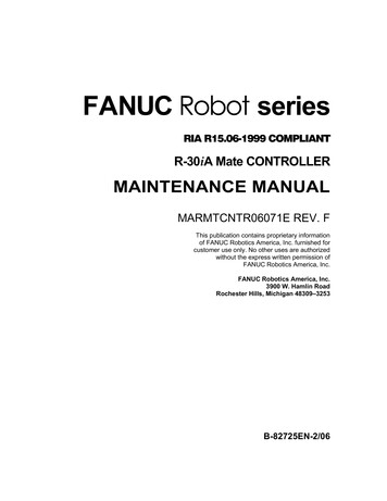
SOUTHERNUNIVERSITYCOLLEGEBUILD A LINE FOLLOWER ROBOTBuild a Line Follower RobotA USER-FRIENDLY GUIDEEDITED BY: CHIA KIM SENG, KANG ENG SIEW, ENG PEI CHEE, HUI SENG KEONGi
Build a Line Follower RobotA User-Friendly GuideEdited byChia Kim SengKang Eng SiewEng Pei CheeHui Seng KeongBuild a Line Follower Robot - A User-FriendlyGuide that edited by Chia Kim Seng, Kang EngSiew, Eng Pei Chee, and Hui Seng Keong islicensed under a Creative Commons AttributionNonCommercial-NoDerivatives 4.0 InternationalLicense. You may download, print out, anddistribute this booklet for educational purposes aslong as recipients do not have to pay. by authors, 2014.Build a Line Follower Robotii
Build a Line Follower Robot - A User-Friendly Guide that edited by Chia Kim Seng,Kang Eng Siew, Eng Pei Chee, and Hui Seng Keong is licensed under a CreativeCommons Attribution-NonCommercial-NoDerivatives 4.0 International License. Youmay download, print out, and distribute this booklet for educational purposes as longas recipients do not have to pay. By authors, 2014.Build a Line Follower Robot - A User-Friendly Guide contains information obtainedfrom authentic and highly regarded resources. Reasonable efforts have been made topublish reliable data and information, but authors, editors and publisher cannotassume responsibility for the validity of all materials or the consequences of their use.The authors and publishers have attempted to trace the copyright holders of allmaterials reproduced in this publication and apologize to copyright holders ifpermission to publish in this form has not been obtained. If any copyright materialhas not been acknowledged please write and let us know so that we may rectify it inany future reprint.Published by:Southern University CollegePTD 64888, 15KM, Jalan Skudai,P.O.Box 76, 81300 Skudai, Johor, MalaysiaTel: 607 558 6605Fax: 607 556 3306Website:http://www.southern.edu.mySponsored by:Southern University College Research Fund (SUCRF)Institute of Graduate Studies and Research (IGSR),Southern University CollegePerpustakaan Negara MalaysiaCataloguing-in-Publication DataBUILD A LINE FOLLOWER ROBOT : A User-Friendly Guide /Edited by Chia Kim Seng, Kang Eng Siew, Eng Pei Chee, Hui Seng KeongAlso available in printReproduction of: BUILD A LINE FOLLOWER ROBOT : A User-FriendlyGuide. Skudai, Johor : Kolej Universiti Selatan, 2014Mode of access: World Wide WebTitle from PDF covereISBN 978-983-2453-46-81. Robotics. 2. Robots--Design and construction. 3. Electronic books.I. Chia, Kim Seng, 1986-. II. Kang, Eng Siew, 1985-.III. Eng, Pei Chee, 1984-. IV. Hui, Seng Keong, 1970-.629.892Build a Line Follower Robotiii
utorsviiiChapter 1 Getting Started with 3pi Robot: Arduino IDE1Chia Kim Seng, Kang Eng Siew, Eng Pei CheeChapter 2 Getting Started with 3pi Robot: Atmel 612Eng Pei CheeChapter 3 Getting started with Arduino Robot19Chia Kim SengChapter 4 Getting Started with FPGA29Eng Pei CheeChapter 5 Line Follower Robot with Arduino UNO41Chia Kim SengChapter 6 Line Follower Robot with DE0-Nano FPGA48Eng Pei CheeChapter 7 Robot Racing56Kang Eng SiewChapter 8 Maze Puzzle63Chia Kim SengChapter 9 C Programming Learning70Chia Kim SengAppendix A77Appendix B78Eng Pei CheeAppendix C83Eng Pei CheeBuild a Line Follower Robotiv
PrefaceApplying the knowledge and skills that students gained from their formal learning tosolve “real-life” engineering problems plays a crucial role to enhance overall teachingand learning process in higher education system. There is a need to find a better wayto equip the students with not only a broader spectrum of knowledge, but alsoreasoning skills that will allow them to work in a wide range of industries.We believe that practical works improve students’ academic interest andperformance in engineering courses. This belief motivates us to complete thishandbook to guide learners to practice their theoretical knowledge using practicalassignment by means of a line follower robot in engineering courses.The main scope of this handbook is to address the practical concerns of building aline follower robot. A line follower robot is a mobile machine that is designed tomove along a given line. This kind of robot has been widely implemented for variouspurposes e.g. transporting goods in manufacturing industries, research experiments,and competitions. Thus, the development of a line follower robot provides analternative practical opportunity for instructors and learners to enrich teaching andlearning experiences.This handbook aims to assist readers to build a line follower robot using an opensource electronics platform based on easy-to-use hardware and software – Arduino.In addition to the use of Arduino IDE, this handbook also presents the use of Atmelsoftware and FPGA to program and to control the robot, respectively.The content of this handbook is categorized into two parts, i.e. Getting Started andExamples of Implementation. In Getting Started, the procedure to getting startedwith 3pi robot using Arduino IDE (Chapter 1) and Atmel 6 (Chapter 2) are presented.Chapter 3 and Chapter 4 introduce Arduino robot and FPGA, respectively. Besides, wealso provide the procedures of self-deploying line follower robots using Arduino UNO(Chapter 5) and FPGA (Chapter 6) as controllers.In Part 2, our results and findings are presented. These results and findings arecompiled into three topics of Robot Racing (Chapter 7), Maze Puzzle (Chapter 8), andC Programming Learning (Chapter 9).Chia Kim SengAugust 2014Build a Line Follower Robotv
AcknowledgmentsWe express our sincere appreciation to the editors who have contributed theirinvaluable knowledge and experience to enrich the content of this handbook. Besidesthat, we would like to gratefully acknowledge the Institute of Graduate Studies andResearch (IGSR) and the Faculty of Engineering and Information Technology of theSouthern University College for providing the Southern University College ResearchFund (SUCRF) and excellent environment for completing our line follower robots andthis handbook. Last but not least, we would like to acknowledge the constructiveadvices and supports provided by the dean of IGSR, Prof. Dr Ho Khai Leong.Thank you.AuthorsAugust 2014Build a Line Follower Robotvi
EditorsChia Kim Seng received his BEng and PhD in electrical and electronic engineeringfrom Universiti Teknologi Malaysia, in 2010 and 2014, respectively. His team and herepresented Malaysia to participate Asia-Pacific Broadcasting Union (ABU) ROBOCON2007 in Vietnam and were awarded the title of Second Runner-up. His main researchinterest is in the field of Machine Learning, Artificial Intelligence, Control,Microcontroller, and Soft Modeling. He has served as a peer reviewer of numerousinternational journals e.g. RCS Analytical Method and IEEE sensor.Kang Eng Siew received her BEng and PhD in electrical and electronic engineeringfrom the Universiti Teknologi Malaysia in 2008 and 2013, respectively. After that, shejoined the postdoctoral program under the Computational Nanoelectronics Researchgroup, Universiti Teknologi Malaysia and has been active in research related tocarbon based devices. Her main research interest is in the emerging area ofnanoelctronics devices, focusing on the use of carbon based materials. She ispresently with the Southern University College as an assistant professor.Eng Pei Chee received her M.Eng degree in Electrical Engineering and B.Eng degree inElectrical and Electronics Engineering, from Universiti Tecknologi Malaysia. From year2007-2008 she worked as a project engineer with the V.S. Electronic Sdn. Bhd. Shejoined the Southern University College in 2011 as a lecturer in the Department ofElectrical & Electronic Engineering. Her research interests include fieldprogrammable gate array (FPGA), VLSI technology, computer architecture, andbiometrics.Hui Seng Kheong received his MSc in Signal Processing from Lancaster University (UK)in 1996 and Ph.D in Electrical and Electronic from Universiti Teknologi Malaysia(UTM)in 2003. From 2003-2007, he worked as a manager with THScan, a biotechnologycompany that specializing thermal texture maps (TTMs) and scanning machines. Hejoined Southern College (later upgraded as Southern University College) in 2007 asDeputy Dean of Faculty of Engineering and Technology. His research interests areEngineering Mathematics, networking, communications, and signal processing.Build a Line Follower Robotvii
ContributorsChia Kim SengFaculty of Engineering and Information TechnologySouthern University CollegeSkudai, JohorMalaysiarespect exist@hotmail.comEng Pei CheeDepartment of Engineering and Electronic EngineeringFaculty of Electronic and Information TechnologySouthern University CollegeSkudai, JohorMalaysiapceng@sc.edu.myKang Eng SiewDepartment of Engineering and Electronic EngineeringFaculty of Electronic and Information TechnologySouthern University CollegeSkudai, JohorMalaysiaeskang@sc.edu.myBuild a Line Follower Robotviii
Chapter 1 Getting Started with 3piRobot: Arduino IDEChia Kim Seng, Kang Eng Siew, Eng Pei Chee1.1IntroductionOrangutan programmer is the default programmer for 3pi robot. This chapteraims to provide essential procedures for first time users to getting started theirproject with 3pi robot quickly. The procedures of relevant software installation,driver installation, and sample programs are included. These procedures havebeen tested using Microsoft Windows 7 and Microsoft Windows 8.1.2Software and driver installationThe procedures that involved to getting started with 3pi robot using Orangutanprogrammer coupled with Arduino IDE are stated as follows:Build a Line Follower Robot1
1. Install Arduino IDE in a computer. ino.cc/en/Main/Software. On the webpage (Figure 1.1), click on the compatible download link todownload the latest Arduino integrated development environment(IDE) software.Figure 1.1 For Windows users, double-clicking on Windows Installer Select Save File. Open the containing folder and run it. Review the software licensing agreement and agree to its terms byclicking I Agree.Build a Line Follower Robot2
In the Installation Options dialog box, select all of the componentsfor installation, and then click NEXT. Specify the name of the folder where you want to install Arduinoproducts. You can either accept the default installation folder orclick Browse to select the desired one. When it is installing, the installer displays the following dialog box.Build a Line Follower Robot3
Once the installation is completed, click Close.2. Install Orangutan Driver to the computer. Download the latest drivers of “Pololu AVR Development Bundle“.By July 2014, the latest is “ Windows (release 140513)” that wasavailable at 140513.exe or http://www.pololu.com/product/1300/resources. Open the containing folder, and then run the installer. In the Pololu AVR Development Bundle Setup dialog box, select allof the components for installation, and then click INSTALL toproceed with the installation.Note: Pololu AVR C/C Library is only required for Atmel Studio IDE (Chapter 2).Build a Line Follower Robot4
During the installation, accept the default installation folder toinstall Pololu USB Programmer Drivers and Pololu Orangutan SVPDrivers by clicking Install. Once the installation is completed, click Close to quit the dialogbox.3. Modify Arduino IDE for 3pi Pololu robots. Two files of boards.txt and programmers.txt in the directory ofC:/ /arduino/hardware/arduino/ (normally it can be found in thesub-folder of Program Files (x86)) is required to be replaced by themodified boards.txt and programmers.txt, respectively, using copyand-paste manner. Please require the files from the authors. Alternatively, users can modify these two files via pasting the codethat stated in Appendix A to the end of the text files accordinglyusing administrator’s authority. If the modification is successful, the option to choose PololuOrangutan as the desired Board and AVR ISP v2 as the desiredProgrammer should be available in the Arduino IDE.Build a Line Follower Robot5
4. Install library for Polulo 3pi robot. pololu.com/docs/0J17/5 (last access: August 2014). In the webpage, double-clicking on Arduino libraries for theOrangutan and 3pi Robot to open the download page (ifapplicable). Download the latest Pololu Arduino Libraries (zip file). If you areusing the old version of Arduino IDE, you need to update the IDEwith the latest version.Figure 1.2 The directory that stores related libraries for 3pi robotBuild a Line Follower Robot6
1.3 After unzipping/extracting the zip file, we need to relocate all thelibrary files to the directory of “My Documents/Arduino/ libraries/”or “Documents/Arduino/ libraries/” as that illustrated in Figure 1.2. If those libraries cannot be found in the Arduino IDE (please checkat File- Examples and File- Sketchbook- libraries in the ArduinoIDE), you may need to manually import the libraries by selectingSketch- Import Library - Add Library in the Arduino IDE, andthen browse the library .zip file.Connect Orangutan programmer to Arduino IDEThis section summarises the important procedure that ensures thecommunication between a computer and a 3pi robot using Orangutanprogrammer can work properly.1. Connect Orangutan programmer to a computer using its USB port. ForWindows 8 users, the Windows will automatically install requireddriver when the programmer is plug-in to the computer.Build a Line Follower Robot7
2. Open Arduino IDE and then change the settings of the IDE as follows.a.Board menu: Tools - Board menu - Pololu OrangutanFigure 1.3 Arduino IDE - Board menub.Programmer: Tools - Programmer - AVR ISP v2Figure 1.4 Arduino IDE – ProgrammerBuild a Line Follower Robot8
c.Programmer’s serial port: Tools - Serial Port - COMFigure 1.5 Arduino IDE - Serial PortNote: The correct Serial Port is dependent on the USB port that has beenconnected to 3pi robot. Thus, in order to select the correct Serial Port, forWindows users, please go to Device Manager as that illustrated below.Figure 1.6 Arduino IDE - Serial Port: Device Manager indicates that the correctSerial Port is COM 9 (Programming Port)Build a Line Follower Robot9
1.4Simple programsAfter completing the first two steps (Section 1.2 and Section 1.3), we can upload asimple program (such as LED blink) to a 3pi robot. Nonetheless, we need to followthe following procedure and precautions to protect the robot.1. Connect Orangutan programmer to a 3pi robot (six pins socket) properly.2. Turn on the robot before uploading program into the robot.3. Ensure that the battery is sufficient. Intuitively, the voltage should morethan 4.6V while a set of four full charged AAA batteries should supplymore than 5V to the robot. Insufficient battery can damage the robotduring uploading. This can be done using read battery millivolts functionas shown in Section 1.4.1.1.4.1 Read battery voltage“read battery millivolts() - performs 10 bits analog-to-digital conversions on thebattery voltage sensing circuit of the 3pi robot and returns the average result inmillivolts. A value of 5234 implies that the voltage of the batteries is 5.234 V. Forfour fully charged AAA rechargeable NiMH batteries, the voltage usually starts at avalue above 5 V, and then drops to around 4 V before the robot shuts off.Therefore, monitoring this number is helpful for determining when we shouldcharge the batteries.”(Reference: Pololu AVR Library Command Reference)Figure 1.7 Arduino IDE - Serial PortBuild a Line Follower Robot10
1.4.2 LED blinkingAccording to the Pololu 3pi robot simplified schematic diagram, the digital pin No.1 and No. 7 are connected to LED. Thus, the code that stated in Figure 1.8 can beused to demonstrate a simple LED blinking.Figure 1.8 Arduino IDE – LED BlinkingFirst, ledR and ledG are defined as pin 1 and pin 7, respectively. After that, thesetwo pins were defined as outputs in setup function using pinMode function. Lastly,digitalWrite function was used to ON or OFF the LED using HIGH to indicate ON,and vice versa. delay function was used to increase the duration of the state (ONor OFF) of the LED. This means that the lower the value of the delay function, thefaster the LED blinks.Tips:Please verify the source code using Arduino IDE before uploading it to a 3pi robot.This practice helps us to figure out the source problem when an error appears.Build a Line Follower Robot11
Chapter 2 Getting Started with 3piRobot: Atmel 6Eng Pei Chee2.1IntroductionThis chapter provides a tutorial on how to get started programming the AtmelAVR microcontroller on a 3pi robot in Windows using the Atmel Studio 6 IDE.Note:This user guide is demonstrated and tested using Windows Vista, Windows 7 //www.pololu.com/docs/0J51 for the installation.2.2Safety precautions before programmingBefore programming, make sure your device is powered. If you are usingrechargeable batteries for your device, make sure they are fully charged. Neverattempt to program your device if the batteries are drained or uncharged. Losingpower during programming could permanently disable a 3pi robot. It is always agood practice to include the battery voltage monitoring function (See Section1.4.1) provided in the library in your program to ensure sufficient amount ofvoltage supplied to the 3pi robot.2.3Installation2.3.1 Installing Atmel Studio 6Download and install Atmel Studio 6 (current version is 6.2 with size ofapproximately 520 MB, updated May 2014), an integrated developmentenvironment (IDE) from Atmel.Build a Line Follower Robot12
The download link of Atmel Studio 6.2 Installer is available athttp://www.atmel.com/tools/atmelstudio.aspx?tab overview.2.3.2 Installing the Pololu AVR Development BundleAfter installing Atmel Studio, download and install Pololu AVR DevelopmentBundle. The download link of Pololu AVR Development Bundle is available ent-bundle.When you are prompted to choose which components should be installed duringthe installation process, select ALL the three components as that illustrated inFigure 2.1.Figure 2.1 The screen of the Pololu AVR C/C Library installerThe descriptions of the three components are as follows:i.ii.Pololu AVR C/C Library - This library is required for Pololu Productsi.e. the Orangutan robot controllers and 3pi robot. [Reference: User’sguide @ http://www.pololu.com/docs/0J20]Pololu USB AVR Programmer – This library contains Pololu USB AVRProgrammer drivers, configuration utility, and SLO-scope software.[Reference: User’s guide @ http://www.pololu.com/docs/0J36]Build a Line Follower Robot13
iii.Orangutan SVP drivers – This is the robot motor controller’s driverthat designed for Atmel AVR microcontroller module or ATmega1284P[Reference: User’s guide @ http://www.pololu.com/docs/0J39]Select “Atmel Studio 6.2” when you are prompted to “Install the library into thefollowing toolchains:”. If the Atmel Studio 6.2 checkbox is grayed out, then theinstaller is unable to find Atmel Studio 6.2. This suggests that you are required toreinstall or repair the installer.Figure 2.2 A screenshot to associate Pololu AVR C/C library with Atmel Studio6.2.During the installation, clicking Install when Windows asks you to install thedrivers.2.4Setting up AVR ProgrammerFollow the following procedures to configure Atmel Studio 6.2 to use theprogrammer.2.4.1 Configure Pololu USB AVR Programmer.Plug the Pololu USB AVR Programmer into your computer’s USB port. Yourcomputer should automatically install the necessary drivers.Build a Line Follower Robot14
Figure 2.3 Configuring Pololu USB AVR Programmer, Drivers InstallationAfter installing the drivers, go to your computer’s Device Manager and expand the“Ports (COM & LPT)” list. You should see two COM ports:“Pololu USB AVR Programmer Programming Port”and“Pololu USB AVR Programmer TTL Serial Port”.In parentheses after these names, you will see the name of the port (e.g. “COM9”or “COM8”).Additionally, there should be a “Pololu USB Devices” list with an entry for theprogrammer.Figure 2.4 Device Manager: The Pololu USB AVR Programmer is recognizedBuild a Line Follower Robot15
2.4.2 Configure Atmel Studio to use the programmer.Open Atmel Studio, with the programmer connected to your computer via USB,and then select Add target from the Tools menu.Apply the following settings, and then click Apply:i. For the tool, select STK500.ii. For the serial port, select the COM port that has been assigned to theprogrammer’s programming port.Figure 2.5 The Add target dialog box in Atmel Studio.2.5Compiling a simple program2.5.1 Creating a new project:Open Atmel Studio 6.2, and then create a new project by selecting New - Project in the File menu.Figure 2.6: The New menu in Atmel Studio 6.Build a Line Follower Robot16
In the New Project dialog, select Installed Templates - C/C - Pololu. Selectthe template 3pi Robot with ATmega328p, and click OK.Remark: If there is no Pololu category, make sure that you have installed thePololu AVR C/C Library and then try to restart Atmel Studio.Figure 2.7 The New Project dialog in Atmel Studio 6.A new project from the template will be opened up as shown in below Figure.Figure 2.8 Installed template programThe template contains some simple codes that demonstrate basic features of theboard, i.e. playing some notes on the buzzer, displaying character on LCD, and LEDblinking.Build a Line Follower Robot17
The functions that being called are defined in the Pololu AVR C/C Library[http://www.pololu.com/docs/0J20].2.5.2 Build the projectBuild/compile the project by selecting Build - Build Solution or by pressing F7. Ifthe build is successful, then the build output will be shown in the “Output” tab atthe bottom should end like this:.Build succeeded. Build: 1 succeeded or up-to-date, 0 failed, 0 skipped 2.5.3 Program the AVR (3pi Robot)Before you start programming the AVR, make sure your 3pi robot is turned on.Losing power during programming could permanently disable your 3pi.You can program by selecting either Continue or Start Without Debugging fromthe Debug menu or simply press the F5 key.If the programming is successful, you should be able to see the program runningon your device. The buzzer should play a note whenever the device starts up.Battery voltage should be displayed on the LCD.The red user LED on the device should be blinking.Build a Line Follower Robot18
Chapter 3 Getting started withArduino RobotChia Kim Seng3.1IntroductionArduino Robot (http://arduino.cc/en/Main/Robot) consists of a build-inprogrammer that is used to communicate with a computer using a Universal SerialBus (USB) A-to-B cable. This chapter aims to provide essential procedure for firsttime users to getting started their project with Arduino Robot quickly. Theprocedure includes relevant software installation, driver installation and a sampleprogram demonstration.3.2Software and driver installationThe procedure involved to getting started with Arduino Robot is as follows:Build a Line Follower Robot19
i.ii.3.3Install Arduino IDE in a computer. The latest Arduino Environment canbe found at http://arduino.cc/en/Main/Software.Connect the Arduino Robot to a computer, and then install uino.cc/en/Guide/Robot.Connect Arduino IDE to Arduino RobotIn this section, the following procedure is required to ensure the communicationcan work correctly.i.ii.Connect Arduino Robot to the computer using USB A-B cable.Open Arduino IDE and then change the settings of the IDE as follows.a.Board menu: Tools Board Arduino Robot ControlFigure 3.1 Arduino IDE - Board menuBuild a Line Follower Robot20
b.Programmer: Tools Programmer Arduino as ISPFigure 3.2 Arduino IDE – set Programmer - Arduino as ISPc.Programmer’s serial port: Tools Serial PortFigure 3.3 Arduino IDE - Serial PortNote: The correct Serial Port is dependent on the USB port that has beenconnected to Arduino robot.Build a Line Follower Robot21
3.4DiscussionThe following sub-sections discuss the operations and the challenges of ArduinoRobot, as well as proposed solution upon the challenges.3.4.1 Control Board Vs Motor BoardArduino robot consists of two separate boards, i.e. Control Board (top) and MotorBoard (bottom). The general function of Control Board is to send a command orcommunicate with Motor Board so that a given task e.g. line following will bedone by the Motor Board. Motor Board, on the other hand, can either follow thecommand given by Control Board or even feedback the command upon thecompletion of the given task. In other words, the main “job scopes” of the MotorBoard are to control the speed and the direction of the motors, and to receive thesignals of the Infrared (IR) sensors.3.4.2 Line Following – ChallengeThe Control Board should not be used to directly analyse the signals from IRsensors and instruct the Arduino Robot to follow a line. This is because theextensive updates of the signals of the IR sensors and also the speed of motor viasending commands from the Control Board to Motor Board and vice versa cancause significant lagging problems.Therefore, we should only use Control Board to send commands e.g. “follow a line”and “chase an object” instead of a routine instruction. The Motor Board, on theother hand, should execute a given command accordingly without any furtherinstruction e.g. the speed and direction of motors. This practice is similar to aneffective management and teamwork strategies that truly reflect the benefit ofsynergy and optimise the limited resource.3.4.3 Speed of MotorAs general practice, the speed of the motor can be controlled using pulse-widthmodulation (PWM) with value ranged from 0 to 255. The motor speed of ArduinoRobot may be different even though the values of the both motors (the left andthe right) are set to the same value. This issue can be rectified by adjusting thetuneable screw on the Motor Board.Nonetheless, I found out that the reverse speed of Right Motor, sometimes, maybe dissimilar to the speed of left Motor. Therefore, in order to command therobot to turn Right, we need to set the speed of the right motor faster than theBuild a Line Follower Robot22
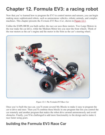
speed of the left motor, e.g. Speed of the Right -180 (negative means reverse)and Speed of the Left 90 for turning the Robot to the Right. Surprisingly, thisissue suddenly disappears after using the Arduino Robot for few weeks. Onepossible explanation is that the hardware might be unstable and need some timeto “warm it up”.Besides, it is found that the speed with pulse-width modulation (PWM) lower than50 is insufficient to make the robot move smoothly. Thus, a commended averagespeed to control the robot is from 120 to 200.Another practical issue of Arduino Robot is that the robot may incapable ofmoving straight using same PWM value. Again, I suspect that this is due to thelimitation of the hardware. One possible solution to address this potential issue isto accelerate the speed of the robot instead of applying constant speed. Thespeed of the robot can be accelerated by increasing the speed of robot gradually.An example program to accelerate the speed of robot is that stated as follows:Figure 3.4 Example program to control the speed of Arduino RobotBuild a Line Follower Robot23
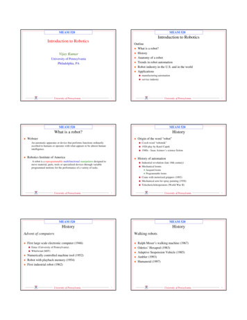
Firstly, the desired maximum speed of the robot to be reached is stored using avariable named speed. After that, a switch function is used to assign the desiredvalue (balance) based on the signals of IR sensors (i.e. position). This value(balance) will be used to adjust the speeds of motors in such ways that the robotwill follow the given line. Two adjustable variables of float speed andfloat balance will be increased or decreased if either of them is not equal to thedesired speed or balance value (line 385). float speed and float balance are thecurrent speed and adjustable speed of motors, respectively.140120Speed, PWM10080Actual Speed60Desired Speed40200010000200003000040000Time, msFigure 3.5 The simulation of the controlled PWMSince the PWM value lower than 50 is insufficient to make the robot moves, Iintentionally set the current speed (i.e. float speed) to 51 if the value is less than50. After that, the current speed will be updated once when the value of update ismore than (maxspeed – (speed – float speed))*ceil(float speed/accelerate). Thevariable of accelerate is a tuneable parameter that used to control the duty cycleof the update. To tune the parameter of accelerate, we can start with accelerate 1. After that, we can increase the value gradually until the response of the robot isstable. Since speed equals to maxspeed in this example, the expression can besimplified as (float speed)*ceil(float speed/accelerate).Current speed will be updated using the equation of float speed ceil((speed –float speed)/5). The value of 5 is intuitively set. Nonetheless, the higher the value,Build a Line Follower Robot24
the amount of the update will be reduce, and vice versa. This equation ensuresthat the incremental of speed will be gradually decreased so that the movementof robot can be more stable. The simulated PWM is illustrated as Figure 3.5.3.4.4 Design of RobotArduino Robot consists of two wheels and two Ball casters. This design may causeone of the wheels becomes unable to contact the horizontal surface properly ifthe horizontal level of the two Ball casters is slight higher than that of the wheels.One possible solution for this matter is to remove one of the Ball casters.3.4.5 Motor ControlIn order to control the motor and to process the IR signals via Motor Control,
with 3pi robot using Arduino IDE (Chapter 1) and Atmel 6 (Chapter 2) are presented. Chapter 3 and Chapter 4 introduce Arduino robot and FPGA, respectively. Besides, we also provide the procedures of self-deploying line follower robots using Arduino