Transcription
WattMaster VAV SystemOperator InterfacesTechnical Guide
Table Of ContentsIntroduction . 3Modular Service Tool . 3Modular System Manager . 3System Connections . 4Modular Service Tool . 4Modular System Manager . 5General Programming Information . 6Operator Interfaces Comparison . 6Service Tool And System Manager . 7Modular System Manager . 7Modular Service Tool . 10Programming The WMVAV Controller . 12Configuration . 12Setpoints . 16Status . 22Scheduling . 24Setting Time & Date . 25Damper Force Modes . 26Outputs Force . 26Programming The VAVBOX Controller . 28Configuration . 28Setpoints . 29Status . 32Damper Force Modes . 34Programming The MiniLink PD . 35Configuration . 35WattMaster Controls Inc.8500 NW River Park Drive · Parkville , MO 64152Toll Free Phone: 866-918-1100PH: (816) 505-1100 · FAX: (816) 505-1101 · E-mail: mail@wattmaster.comVisit our web site at www.wattmaster.comForm: WM-SMST-TGD-01CCopyright 2004 WattMaster Controls, Inc.WattMaster Controls, Inc. assumes no responsibility for errors, or omissions.This document is subject to change without notice.
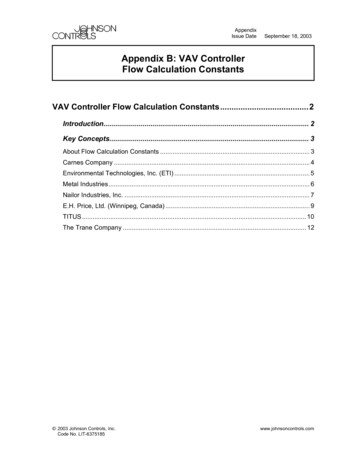
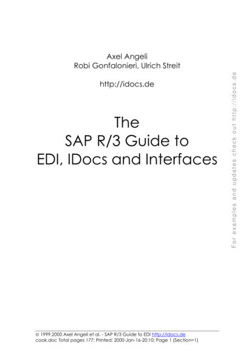
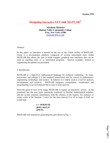
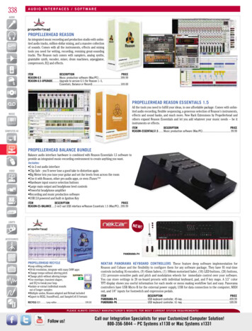
Technical GuideIntroductionModular Service ToolModular System ALARMS123CONFIGURATION456BALANCE - TEST789DEC0MINUSON-1.63"Figure 1: Modular Service Tool DimensionsDescriptionThe OE391-05 Modular Service Tool is a system operator interfacethat provides a direct link to enable the system operator to view thestatus, configure and to adjust the setpoints of any controller on thecontrol system communications loop. The Modular Service Tool ishoused in an attractive beige colored plastic enclosure. The displayarea is covered with a clear plastic bezel for protection of the displayscreen. The Modular Service Tool has a four line by 20 character display panel with adjustable contrast control and a 27 key membranekeypad for data selection and entry. All keypad operations are simpleand straight forward, utilizing non-cryptic plain English languagemessages. Menu driven programming allows for easy setup and operation without the need for specialized training. The OE391-05 Modular Service Tool is supplied with (4) AA (1.5V) Volt alkaline batteriesa wall mount DC power supply and a communication cable terminatedwith an 8 pin DIN connecter for connection to the Service Tool. Thecable allows the user to setup and program any WattMaster VAV controller with a 8 pin DIN connector socket by simply plugging in theservice tool to the socket on the controller. An adapter is also providedto allow connection to the 3 pin communications terminal block oncontrollers which do not have the 8 pin DIN connector.The Modular Service Tool is designed to be carried by the system installer or service technician. Its rugged plastic housing, provides superior protection for the electronic components housed inside. The OE39105 Modular Service Tool is a top quality service tool that will stand upto the demands of the typical job site environment for many years.Operator InterfacesFigure 2: Modular System Manager DimensionsDescriptionThe OE392-05 – Modular System Manager provides a direct link toenable the system operator to view the status and to adjust the setpointsof any controller on the control system communications loop. The Modular System Manager is designed to be used with the WattMaster VAVControl System. The System Manager is housed in an attractive offwhite colored plastic enclosure. The System Manager is equipped witha four line by 20 character backlighted display panel and a 24 key membrane keypad for data selection and entry. All keypad operations aresimple and straight forward, utilizing non-cryptic plain English languagemessages. Menu driven programming allows for easy setup and operation without the need for specialized training. The System Manager alsohas 2 integral LED’s for user notification of system alarm conditionsand override initiations. Protection from unauthorized users is providedby the System Manager’s integral multi-level passcode authorizationprogramming.On WattMaster VAV Systems, the Modular System Manager is wired tothe communications and power loop of the system via a pigtail cablewith modular connectors on one end and stripped wire ends on the otherthat is provided with the System Manager. This pigtail cable allowsconnection of power to the Modular System Manager from a 24 VACpower source and communications wiring from the HVAC unit controller communication wiring terminals.The Modular System Manager is designed for wall mounting. Mounting holes are provided to attach the Modular System Manager to a standard handy box. It is recommended that the System Manager be mountedat approximately eye level to allow for ease of programming and reading of the display. The System Manager is typically mounted in thebuilding manager or superintendent’s office or in an equipment room.The attractive enclosure is quite suitable for mounting in any locationor with most decors.3
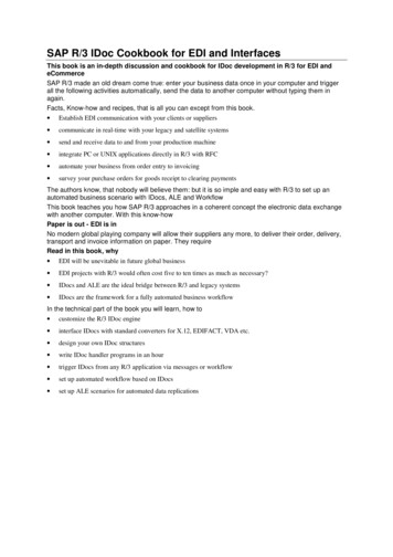
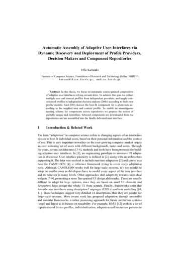
Technical GuideSystem ConnectionsModular Service ToolWether you have a Stand Alone, Interconnected or Networked System,the Modular Service Tool always connects to an HVAC unit controllervia a prefabricated cable that is supplied with the service tool. The Modular Service Tool cable is terminated on both ends with a mini DIN connector. Attach one end to the Modular Service Tool and the other end tothe mini DIN connector on the HVAC unit controller. If this is an Interconnected System, all controllers that are interconnected with commu-nications cable can be programmed from any HVAC unit controller onthe loop. If this is a Networked System, all controllers on the entireNetworked System can be programmed from one HVAC unit controller.Be sure that the Modular Service Tool has fresh batteries installed orthat it is connected to a power source using the supplied power packbefore attempting any programming of the controller. See Figure 3 forconnection details.Optional Connection ForControllers Without DIN ConnectorPL101904 Adapter BoardTerminal Block Base(Remove Terminal Block)COMMTSHLDRFemale DIN ConnectorMale DIN ConnectorTypical Controller BoardThe Modular Service Tool Can Be Connected To MostControllers By Plugging One End Of The SuppliedCable Into the Modular Service Tool DIN ConnectorAnd The Other End Into The DIN Connector On TheControllers.Connector CableSome Controllers Without DIN Connectors RequireUse Of The Supplied PL101904 Adapter Board ShownAbove. To Connect With Adapter Board, First UnplugCOMM Terminal Block From Controller Board. PlugPL101904 Adapter Board Terminal End Into TerminalBlock Base On Controller. Plug DIN Connector CableInto DIN Connector On PL101904 Adapter Board . SeeOptional Connection For Controllers Without DINConnector Above For Illustration Of This Connection.Modular Service 56BALANCE - TEST789DEC0MINUSONBe Sure The Modular ServiceTool Is Connected To TheSupplied Power Pack Or HasFresh Batteries Installed BeforeAttempting Programming Of TheController. Be Sure The Power IsTurned Off On The ModularService Tool Before ConnectingThe Cable To The Controller.-Power On ButtonFigure 3: Modular Service Tool4Operator Interfaces
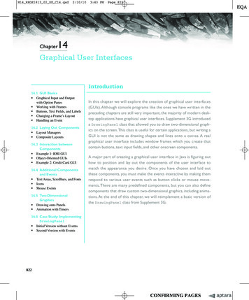
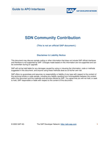
Technical GuideModular System ManagerPower and communications are supplied to the System Manager via amodular/pigtail cable that is supplied with the System Manager. Thiscable has a male Molex connector on one end for connection to thefemale Molex connector on the System Manager. On the other end are 5insulated wires with a drain wire which are used for connection to thecommunication and power wiring from the transformer and from thelocal loop communications terminal on the WMVAV controller or anyVAVBOX controller’s communication terminal. A class II, 24 VACtransformer (by others) rated at 6 VA or greater load capacity is requiredfor powering the System Manager.See Figure 4 & 5 for System Manager connection and wiring 6R1374HC923C4EPROMCX11COMM OMM INR11R12D5CX8R10D5CX8COMM OUTP1COMM CB80C552-5-16WPP442860 2/5PDfD9722V7 16WPP442860 2/5PDfD9722V7 14Modular System ManagerBack of Front CoverModular System ManagerBack of Front CoverUse Supplied ModularCable With Stripped EndsFor Connection To TerminalBlock And TransformerTSHLDRRED(24CVA2-Conductor Shielded18-GuageCommunications Wire)Class 2 TransformerRated For 6 VA MinimumNDN (GEEGRWMVAV Controller BoardConnection ShownMay Also Be Connected To AnyVAVBOX Controller On LoopTSHLDRBLACK (R)NOWBR))ND(GWHITE (T)WHITE (T)DRAIN WIRE (SHLD)BLACK (R)RED (24 VAC)BROWN (GND)GREEN (GND)HZ000121Modular Pigtail CableSupplied With System ManagerHandy Box , Conduit,Fittings, Wire Nuts,Butt Splices Etc.,( By Others)LINEVOLTAGEDrain Wire (Shld)Controller BoardClass 2 TransformerRated For 6 VA Minimum(By Others)LINE VOLTAGEFigure 4 Schematic for Wiring System ManagerUsing Modular Cable PigtailOperator InterfacesFigure 5: Detailed Typical System Manager WiringUsing Modular Cable Pigtail5
Technical GuideGeneral Programming InformationOperator Interfaces ComparisonIn order to configure and program the WattMaster VAV System controller
Networked System can be programmed from one HVAC unit control-ler. Be sure that the Modular Service Tool has fresh batteries installed or that it is connected to a power source using the supplied power pack before attempting any programming of the controller. See Figure 3 for connection details. Figure 3: Modular Service Tool Typical Controller Board Connector Cable Modular Service Tool