Transcription
HW HCORPORATIONRSERVICE MANUALHWH TOUCH PANEL-CONTROLLED625 SERIES HYDRAULIC LEVELING SYSTEMRFEATURING:Touch Panel Leveling ControlBI-AXIS Hydraulic Leveling(Without Dump)(With Dump)(With Pilot Dump)RHWH COMPUTERIZED LEVELINGRONAUTOSTOREOFFEXCESSSLOPENOT INPARK/BRAKETRAVELMODECAUTION!UNDERSTAND OPERATOR’S MANUAL BEFORE USING. BLOCK FRAME AND TIRESSECURELY BEFORE REMOVING TIRES OR CRAWLING UNDER VEHICLE.HWH CORPORATION(On I-80, Exit 267 South)2096 Moscow Road Moscow, Iowa 52760Ph: 800/321-3494 (or) 563/724-3396 Fax: 563/724-3408www.hwh.comML35963/MI91.002616JUN05
SECTION 1TIONSEC1TEMSYS TIONRAOPE OUBLETRAND OTINGSHO IDEGUSECTION2DIAGRAMSANDGLOSSARY2 PART FOLDERHOW TO USE MANUALThis manual is written in two sections. Section 1 is System Operation and Trouble Shooting Steps. Section 2 is theDiagrams and Parts Glossary. Begin diagnosis of the system with Section 1. This will give the correct operation and functionof the system. The Trouble Shooting Steps are written in order of operation. The Trouble Shooting Steps should be followedin order to avoid improper diagnosis of the system. Section 2 contains diagrams and a parts glossary. Refer to diagrams asdirected in the Trouble Shooting Steps. The parts glossary explains the function of individual parts.Before beginning your repair, it is IMPORTANT to read the CAUTIONS and NOTES AND CHECKS in the first section, TROUBLESHOOTING GUIDE. In many cases this will save time and mistakes when trouble shooting a system.This Repair Manual is offered as a guide only. It is impossible to anticipate every problem or combination of problems. Forany problems encountered that are not addressed in this manual, contact HWH Corporation for assistance. (800-321-3494)PROCEED WITH SYSTEM OPERATIONMI91.113231MAY05
TROUBLE SHOOTINGCAUTIONS!BLOCK FRAME AND TIRES SECURELY BEFORE CRAWLING UNDER VEHICLE. DO NOT USE THE LEVELINGJACKS OR AIR SUSPENSION TO SUPPORT VEHICLE WHILE UNDER VEHICLE OR CHANGING TIRES. VEHICLEMAY DROP AND OR MOVE FORWARD OR BACKWARD WITHOUT WARNING CAUSING INJURY OR DEATH.WHEN ROUTING OR REROUTING HYDRAULIC HOSES AND WIRES, BE SURE THEY ARE NOT EXPOSED TO ENGINEEXHAUST OR ANY HIGH TEMPERATURE COMPONENTS OF THE VEHICLE.NEVER PLACE HAND OR OTHER PARTS OF THE BODY NEAR HYDRAULIC LEAKS. OIL MAY CUT AND PENETRATE THE SKIN CAUSING INJURY OR DEATH.SAFETY CLASSES ARE TO BE WORN TO PROTECT EYES FROM DIRT, METAL CHIPS, OIL LEAKS, ECT. FOLLOWALL OTHER SHOP SAFETY PRACTICES.NOTES AND CHECKSRead and check before proceeding with Trouble Shooting Steps.NOTE: HWH CORPORATION ASSUMES NO LIABILITYFOR DAMAGES OR INJURIES RESULTING FROM THEINSTALLATION OR REPAIR OF THIS PRODUCT.1. If the jacks cannot be retracted, see TROUBLE SHOOTINGPART 15 Step 2 for temporary measures. Make sure the manualretract valves are closed before trouble shooting.2. The Trouble Shooting Guide must be followed in order.Problems checked for in one step are assumed correct andmay not be checked again in following steps.3. Check that the oil reservoir is full with the jacks in the fullyretracted position. If the vehicle is equipped with HWH roomextensions, refer to the HWH Owners Manual for properposition of the room when checking the oil level.4. Most coaches have more than one battery; one for theengine and the other(s) for the coach. The engine batterysupplies power for the control box and hydraulic pump.Batteries under no load should read 12.7 volts. Batteriesmust maintain good voltage under load. Batteries must be ingood condition with no weak cells. The system will draw up to200 amps. An alternator, convertor or battery charger will notnot supply enough power for the system to operate properly.5. Proper grounding of all components is critical. See theelectrical circuit for specific grounds required. Faulty grounds,especially for the control box, solenoid manifold or the pumpassembly, may cause control box component damage and /orimproper or erratic operation.6. Do not replace the control box unless the Repair Steps sayto replace it. Otherwise the malfunctions may damage thenew control box.This manual is intended for use by experienced mechanicswith knowledge of hydraulic and automotive electricalsystems. People with little or no experience with HWHleveling systems should contact HWH technical service(800-321-3494) before beginning. Special attention shouldbe given to all cautions, wiring, and hydraulic diagrams.Special note: When installing a new control box, makesure the box is properly grounded before applying powerto the system.Tightening of hose ends: If tightening a new hose end,make the hose end snug (finger tight) on the fitting, thentighten the hose end 1/3 turn (2 FLATS). If tightening anexisting hose end, tighten the hose end to snug plus 1/4turn (1 FLAT).Suggested tools for trouble shooting the HWH leveling systems:JUMPER WIRES(UP TO 10 GAUGE)PRESSURE GAGE(3500 PSI MIN.)MULTI-METER12 VOLT TEST LIGHTPROCEED WITH THE TROUBLESHOOTING STEPS ON THEFOLLOWING PAGEMI91.114231MAY05
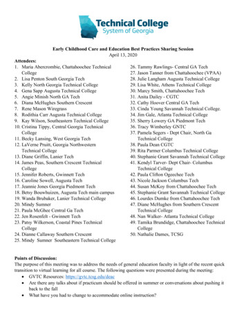
CONTROL IDENTIFICATION625 SERIES LEVELING SYSTEMCOMPUTER-CONTROLHYDRAULICOPERATIONIndicator light"EXCESS SLOPE"Indicator lightLOWER FRONTManual buttonRAISE FRONTManual buttonON/AUTOButtonHWH COMPUTERIZED LEVELINGR"NOT IN PARK"Indicator lightONAUTOSTOREIndicator CK DOWNIndicator light(4) redNOT INPARK/BRAKERAISE RIGHT SIDEManual buttonTRAVELMODELOWER RIGHT SIDEManual buttonCAUTION!UNDERSTAND OPERATOR’S MANUAL BEFORE USING. BLOCK FRAME AND TIRESSECURELY BEFORE REMOVING TIRES OR CRAWLING UNDER VEHICLE."TRAVEL MODE"Indicator lightLEVEL SENSINGIndicator light(4) yellowRAISE REARManual buttonRAISE LEFT SIDEManual buttonLOWER REARManual buttonLOWER LEFT SIDEManual buttonCONTROL FUNCTIONSCONTROL BUTTONSON/AUTO (I) BUTTON: This is the on button and automaticoperation button. The on indicator light is above the (I)button."OFF" BUTTON: Push the "OFF" button to stop hydraulicoperation."STORE" BUTTON: The store indicator light is above the"STORE" button. This button is used to automatically retractthe jacks.EXTEND BUTTONS (UP ARROWS): These buttons willextend their respective jack pairs to lift the vehicle.RETRACT BUTTONS (DOWN ARROWS): These buttonswill retract their respective jack pairs to lower the vehicle.INDICATOR LIGHTSHYDRAULIC OPERATIONS (I) LIGHT: This light indicatesthat the panel is active."NOT IN PARK/BRAKE" LIGHT: This indicator will lightwhen the hand/auto brake is not set and the "LEVEL"button is being pushed.INDICATOR LIGHTS (Continued)STORE LIGHT: This light indicates that the systemis in STORE mode."TRAVEL MODE" LIGHT: This indicator light will be onwhen the ignition is on, when the jacks are retracted andthere are no red WARNING lights on.LEVELING LIGHTS: The four yellow indicating lights arelevel sensing indicators. When a yellow light is on, itindicates that its side, end, or corner of the vehicle is low.No more than two lights should be on at the same time.JACK DOWN LIGHTS: The four red lights surrounding theyellow level indicators are jacks down WARNING lights.They are functional only when the ignition is in the "ON"or "ACC" position, the system is on, and the jacks areextended 1/4 to 1/2 inch.MASTER "JACKS DOWN" WARNING LIGHT: This is alight mounted in the dash separate from the touch panel.It will be on when any one or more jacks are extendedand the ignition is "ON".BUZZER: This is a jacks down warning. It will sound if themaster "JACKS DOWN" warning light is on.MI91.115231MAY05
SYSTEM OPERATIONThe 625 leveling system is a computer controlled, BI-AXIS push button system. This system has automatic or optional manualcontrol. This system will always extend two (2) jacks at the same time in the automatic or manual mode, both front jacks, theleft front and left rear jacks, the right front and right rear jacks or both rear jacks. In the manual mode, the jacks are controlledby the UP and DOWN arrow buttons on the right hand side of the touch panel. The UP arrows extend jack pairs and the DOWNarrows retract jack pairs.If the vehicle is equipped with an air suspension, the air must be exhausted from the suspension before leveling the vehicle. Ifthe air is not exhausted, the suspension height control valves will interfere with the leveling procedure. There are two types ofair dump systems that HWH controls. One system uses air solenoid valves supplied by HWH. The second system is suppliedby the chassis manufacturer. This is a pilot air dump system. In the automatic mode, the air is dumped automatically beforethe leveling process is started. For manual leveling, the HWH touch panel has a "DUMP" button. The "DUMP" button will onlywork if the POWER ON light is on. If the vehicle uses the HWH air dump valves, the "DUMP" button must be pushed and helduntil all of the air is exhausted from the vehicle suspension system. The engine must be off. If a pilot air dump system is used,the engine may be on or off. The "DUMP" button can be pushed and released. The pilot air dump system will return to thetravel position if the ignition is on and the "STORE" button is pushed or the park brake is released.AUTOMATIC OPERATIONThe ignition must be in the "ON" or "ACC." position and the park brake must be set to turn the system on. The "NOT IN PARK/BRAKE" indicator light will come on while the "ON" button is being pushed if the park brake signal is not present. The systemwill not turn on.Pushing the "ON" (I) button will turn the system on. The POWER ON light should be lit and the DUMP button will function.Push the "ON" (I) button a second time. The POWER ON light will flash.On the right hand side of the touch panel there are four (4) red and four (4) yellow indicator lights. The four red indicator lightsare JACK DOWN warning lights. There is one light for each jack. These warning lights come on when their respective jacksare extended about 1/4 to 1/2 inch. The four yellow indicator lights are level indicators, front, left side, right side and rear. A lityellow level light indicates that a side, end or corner is low. When all four yellow level lights are out, the vehicle is level withinthe tolerance of the level sensing unit.The computer will extend jack pairs according to the level lights starting with a lit side light. When all four level lights are out,the computer will extend any jacks not used for leveling to stabilize the vehicle. The computer looks for a jack pressure switchfrom each jack to know all jacks are on the ground. NOTE: Both front solenoid valves will come on during the stabilizeprocedure when either front jack pressure switch is not on. When both front jack pressure switches are on, both frontsolenoid valves will be off.EXCESS SLOPE: Excess slope is when a pair of jacks extend as far as they can without turning a yellow level light out. Thepump will go to relief and trip a 3000# pressure switch on the leveling manifold. The "EXCESS SLOPE" light will come on.Jacks that have not been extended will not extend when the "EXCESS SLOPE" light is on. The "EXCESS SLOPE" light will beon whenever the ignition is on until the park brake is released (with the ignition on) or the jacks are completely retracted with the"STORE" button.The "OFF" button will turn the system off at any time.MANUAL OPERATIONThe ignition must be in the "ON" or "ACC." position and the park brake must be set to turn the system on. The "NOT IN PARK/BRAKE" indicator light will come on while the "ON" button is being pushed if the park brake signal is not present. The systemwill not turn on.Pushing the "ON" (I) button will turn the system on. The POWER ON light should be lit. With the POWER ON light on, the UPor DOWN arrows and the DUMP button will function.Use the DUMP button to dump the air before extending jacks.MI91.116216JUN05
625 TROUBLE SHOOTING GUIDEOn the right hand side of the touch panel there are four (4) red and four (4) yellow indicator lights. The four red indicator lightsare JACK DOWN warning lights. There is one light for each jack. These warning lights come on when their respective jacksare extended about 1/4 to 1/2 inch. The four yellow indicator lights are level indicators, front, left side, right side and rear. A lityellow level light indicates that a side, end or corner is low. When all four yellow level lights are out, the vehicle is level withinthe tolerance of the level sensing unit.Use the UP ARROW (Extend jack pairs) and DOWN ARROW (Retract jack pairs) buttons to extend jack pairs asneeded to level and stabilize the vehicle. Side level lights should be turned off before turning off front or rear level lights.The "OFF" button will turn the system off at any time.STORE MODEThe touch panel has a "STORE" button and light. The "STORE" button will work with the POWER ON light on or off.The ignition must be in the "ON" or "ACC." position. The STORE light will come on when the "STORE" button is pushed. TheSTORE light will go out six (6) minutes after the last of the four individual red WARNING lights go out. If the POWER ON lightis on while the STORE light is on, the POWER ON light will go out at this time also.The "STORE" button should always be used to retract the jacks. This allows the system to store any jack that extends due tothermal expansion of the hydraulic fluid while traveling.MI91.117231MAY05
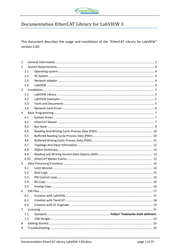
625 TROUBLE SHOOTING STEPSMANUAL OPERATIONNOTE: The following diagnostic functions are written in order of operation and should be checked in this order.Failure to do so may cause improper diagnoses of the problem(s) and increase the time needed to repair the system.PART 1. WITH THE IGNITION OFF THE HWH TOUCH PANEL SHOULD HAVE NO LIGHTS ONAND SHOULD NOT FUNCTION.ELECTRICAL CONNECTION DIAGRAM625 SERIES LEVELING SYSTEMAIR DUMP - PARK BRAKE - MASTER WARNING LIGHT AND BUZZERTOUCH PANEL - JACK WARNING LIGHTS AND PRESSURE SWITCHESPRESSURESWITCHPRESSURESWITCHTOUCH PANELHWH COMPUTERIZED TCHNOT INPARK/BRAKESTORE DUMPOFFB ATRAVELMODECAUTION!B AUNDERSTAND OPERATOR’S MANUAL BEFORE USING. BLOCK FRAME AND TIRESSECURELY BEFORE REMOVING TIRES OR CRAWLING UNDER VEHICLE.6235LEFT FRONT20001000RIGHT FRONT62351200220061101. If the touch panel has lights on or will function, the red 6120 wirein the touch panel harness is connected to a constant power sourceand should be moved to the "ACC." side of the ignition switch.SEE: MP85.102A or MP85.056CMASTERWARNINGLIGHT930093016230 - 6231TO IGNITIONPILOT DUMPCONNECTIONBY OEMTO ACCESSORYFUSE5AMPBUZZER6120SEE ELECTRICAL CONNECTIONDIAGRAM - 625 SERIESLEVELING SYSTEM - LEVELINGMANIFOLD - PUMP ANDMASTER RELAYS DIODE6111611176997699769912 PINBROWN9000PARK BRAKESWITCH769990009001 - TOPARK BRAKELIGHTDIODE12 PINGREEN12 PINBLACK4 PINGRAY8 PINBLACK12 PINGRAYTO HWHGROUNDSTUDCBA623162306231623093009301PILOT AIR WARNINGSWITCHWARNINGSWITCHB AB A30006235LEFT REARRIGHT 5.056CELECTRICAL CONNECTION DIAGRAM625 SERIES LEVELING SYSTEMCONTROL BOX - LED - FUSE LOCATION AND MPTRAVELPUMPRELAYMASTERRELAY2129 30 31 32 33 34 35222324F11F101. The "TRAVEL MODE" light is not on. The ignition is on, the master "JACKS DOWN"warning light and buzzer are on and none of the jacks are RIGHTREAR1RIGHTFRONTPART 2. WITH THE IGNITION ON, THE "TRAVEL MODE" LIGHT IS THE ONLY LIGHT ON THETOUCH PANEL THAT SHOULD BE ON. THE MASTER "JACKS DOWN" LIGHT ANDBUZZER SHOULD NOT BE ON.25SENSING UNIT26PIN 127FUSE 7.5 AMP 12 ACC TOTOUCHF12PANEL28 12VREARRIGHT SIDEFRONTLEFT SIDEGROUND36 37 3839NOTE: FOR DETAILED INPUT / OUTPUTINFORMATION ABOUT PIN CONNECTIONS SEEELECTRICAL CONNECTION DIAGRAM - CONTROLBOX CONNECTION INFORMATION.RELAY DESCRIPTIONFUSERIGHT REAR COILRIGHT REAR OUTPUTLEFT REAR COILLEFT REAR OUTPUTRIGHT FRONT COILRIGHT FRONT OUTPUTLEFT FRONT COILLEFT FRONT OUTPUTDUMP COILDUMP OUTPUTMASTER RELAY COILMASTER RELAY OUTPUTPUMP COILPUMP OUTPUTTRAVEL COILTRAVEL OUTPUTCRX 2CRX 1LEFT FRONT WARN SWRIGHT FRONT WARN SWRIGHT REAR WARN SWLEFT REAR WARN SWLEFT FRONT PRESS SWRIGHT FRONT PRESS SWRIGHT REAR PRESS SWLEFT REAR PRESS SWNOT USEDNOT USED3000 LB PRESS SW INPUTMASTER WARN CONTROL50 LB PRESS SW INPUTJACK INTERRUPTPARK BRAKEBOARD ENABLEACCESSORY INACCESSORY OUT FORMASTER WARNINGLINK LIGHTF1 - 15 AMPF2 - 15 AMPF3 - 15 AMPF4 - 15 AMPF6 - 5 AMPF7 - 5 AMPF8 - 5 AMPF9 - 5 AMPF10 - 10 AMPF11 - 3 AMPLED’S 19 AND 20 (YELLOW) WILL BE ON WHENEVER THETOUCH PANEL IS ON UNLESS THE "STORE" BUTTON ISPUSHED. TWO SECONDS AFTER THE "STORE" BUTTONIS PUSHED, LED’s 7 AND 20 WILL TURN OFF. 5 SECONDSLATER LED’S 3 AND 19 WILL TURN OFF.A LIT RED LED INDICATES THERE ISVOLTAGE ON IT’S CORRESPONDING OUTPUT PIN.IF A YELLOW LED IS LIT AND THECORRESPONDING RED LED IS OFF, EITHERIT’S FUSE IS BLOWN OR THE RELAY IS BAD.NOTE: THE TRAVEL RELAY IS WIRED AS ANORMALLY CLOSED RELAY. WHEN THE YELLOWLED (17) IS ON THE RELAY CONTACTS WILL OPEN.THE RED LED (18) WILL NOT BE ON. THE RED LEDWILL BE ON IF THE LEVELING SYSTEM IS IN THETRAVEL MODE AND THE IGNITION IS ON.IF THE YELLOW LED’S ARE WORKING BUTNO RED LED IS COMING ON THERE MAY BEPROBLEM WITH INPUT VOLTAGE IN THE4-PIN CONNECTOR.IF A YELLOW LED IS NOT LIT, THERE IS APROBLEM WITH THE CONTROL BOX, TOUCH PANELOR CONNECTION CABLENOTE: THE TRAVEL RELAY IS NOT USED ONVEHICLES EQUIPPED WITH HWH AIR DUMP SYSTEMS.IT IS ONLY USED WITH PILOT OPERATED AIR DUMPSYSTEMS.MP85.184C27APR05MP85.184CELECTRICAL CONNECTION DIAGRAM625 SERIES LEVELING SYSTEMAIR DUMP - PARK BRAKE - MASTER WARNING LIGHT AND BUZZERTOUCH PANEL - JACK WARNING LIGHTS AND PRESSURE SWITCHESPRESSURESWITCHTOUCH PANELHWH COMPUTERIZED LEVELINGHYDWARNINGSWITCHLEVELWARNINGSWITCHNOT INPARK/BRAKEOFFPRESSURESWITCHEXCESSSLOPESTORE DUMPB ATRAVELMODECAUTION!B AUNDERSTAND OPERATOR’S MANUAL BEFORE USING. BLOCK FRAME AND TIRESSECURELY BEFORE REMOVING TIRES OR CRAWLING UNDER VEHICLE.6235LEFT FRONT20001000RIGHT 0 - 6231TO IGNITIONPILOT DUMPCONNECTIONBY OEMTO ACCESSORYFUSE5AMPBUZZER6120SEE ELECTRICAL CONNECTIONDIAGRAM - 625 SERIESLEVELING SYSTEM - LEVELINGMANIFOLD - PUMP ANDMASTER RELAYS DIODE6111611176997699769912 PINBROWN9000PARK BRAKESWITCH769990009001 - TOPARK BRAKELIGHTDIODE12 PINGREEN12 PINBLACK4 PINGRAY8 PINBLACKTO HWHGROUNDSTUD62316230AIf a warning switch LED is on, unplug the warning switch for the jacksthat have a lit LED. If the LEDs go out, the problem is the warning switch.NOTE: The magnet in the jack may be bad. If a new switch does not fixthe problem, contact HWH customer service. If the LED stays on with thewarning switch unplugged, unplug the 12 pin gray connector from the backof the control box. If the LED remains on, replace the control box. If theLED goes out, the warning switch wire(s) for the LEDs that are on areshorted to ground. SEE: MP85.102A or MP85.056C39-REDNOTE: A LIT YELLOW LED INDICATES THEREIS A GROUND SIGNAL TO TURN THECORRESPONDING RELAY ON.Bb.Check the four yellow LEDs for the warning switch inputs in the controlbox. Number 21 is for the left front jack, 22 is for the right front jack,23 is for the right rear jack and 24 is for the left rear jack. If no warningswitch LEDs are on, replace the control box. SEE: D36-RED37-RED38-RED12 PINGRAY6231623093009301PILOT AIR WARNINGSWITCHWARNINGSWITCHB AB A6235LEFT REAR30004000RIGHT REAR6235420032002. The "TRAVEL MODE" light is not on. The ignition is on, the master "JACKS DOWN"warning light and buzzer are NOT on and none of the jacks are h the ON (I or HYD) button. If the panel will turn on replace the control box.If the panel will not turn on, proceed to PART 4.3. The "TRAVEL MODE" light is on AND the master "JACKS DOWN" warning light and buzzer are on.Check red LED 32. If the LED is on, replace the control box. SEE: MP85.184CIf the LED is not on, the 7699 wire going to the master warning light and buzzeris shorted to ground. SEE: MP85.304R & MP85.102A or MP85.056CELECTRICAL CONNECTION DIAGRAMPRESSURESWITCHTOUCH PANELHWH COMPUTERIZED LEVELINGHYDWARNINGSWITCHLEVELWARNINGSWITCHNOT INPARK/BRAKEOFFTRAVELMODECAUTION!SECURELY BEFORE REMOVING TIRES OR CRAWLING UNDER VEHICLE.20002200930093016230 - 6231TO ELAY21F915F8F71329 30 31 32 33 34 3522F11F102324SENSING UNITPIN 125262728 12VREARRIGHT SIDEFRONTLEFT SIDEGROUNDFUSE 7.5 AMP 12 ACC TOTOUCHF12PANEL36 37 3839NOTE: FOR DETAILED INPUT / OUTPUTINFORMATION ABOUT PIN CONNECTIONS SEEELECTRICAL CONNECTION DIAGRAM - CONTROLBOX CONNECTION INFORMATION.NOTE: A LIT YELLOW LED INDICATES THEREIS A GROUND SIGNAL TO TURN THECORRESPONDING RELAY ON.A LIT RED LED INDICATES THERE ISVOLTAGE ON IT’S CORRESPONDING OUTPUT PIN.IF A YELLOW LED IS LIT AND THECORRESPONDING RED LED IS OFF, EITHERIT’S FUSE IS BLOWN OR THE RELAY IS BAD.IF THE YELLOW LED’S ARE WORKING BUTNO RED LED IS COMING ON THERE MAY BEPROBLEM WITH INPUT VOLTAGE IN THE4-PIN CONNECTOR.IF A YELLOW LED IS NOT LIT, THERE IS APROBLEM WITH THE CONTROL BOX, TOUCH PANELOR CONNECTION CABLE39-REDA MASTER WARNING INDICATOR SHOULD ALWAYS BE USED. WHEN THE LEVELING SYSTEM HASSTRAIGHT-ACTING JACKS A WARNING BUZZER MUST BE USED.6111NOTE: BY SUPPLYING IGNITION POWER TO THE WARNING BUZZER AND LIGHT, AND "ACC" POWER TO THECONTROL BOX, THE SYSTEM MAY BE OPERATED IN ACCESSORY WITHOUT THE BUZZER SOUNDING.THE NEGATIVE SIGNAL FOR THE WARNING INDICATORS MUST ALWAYS COME FROM THE CONTROL BOX.SEE ELECTRICAL CONNECTIONDIAGRAM - 625 SERIESLEVELING SYSTEM - LEVELINGMANIFOLD - PUMP ANDMASTER RELAYSF6 - 5 AMPF7 - 5 AMP5-15 AMP FUSEF8 - 5 AMPJACKDOWNLIGHTCONNECT THIS END TO 12 VOLT IGNITION "ON" POWERPIGTAIL W/DIODEAND IN-LINEFUSE HOLDER - 612112 PINBROWN90009001 - TOPARK BRAKELIGHTDIODEF4 - 15 AMPSEE CONTROL BOXCONNECTIONINFORMATION769990004 PINGRAY12 PINGREEN12 PINBLACK8 PINBLACKTO HWHGROUNDSTUD62316230BUZZER12 PINGRAY6231623093009301PILOT AIR DUMPCONNECTION76996111WARN URESWITCHWARNINGSWITCHPIGTAIL PROVIDED - 7699PRESSURESWITCHWARNINGSWITCHB AB A6235LEFT REAR4000F10 - 10 AMP4200F11 - 3 AMPLED’S 19 AND 20 (YELLOW) WILL BE ON WHENEVER THETOUCH PANEL IS ON UNLESS THE "STORE" BUTTON ISPUSHED. TWO SECONDS AFTER THE "STORE" BUTTONIS PUSHED, LED’s 7 AND 20 WILL TURN OFF. 5 SECONDSLATER LED’S 3 AND 19 WILL TURN OFF.NOTE: THE TRAVEL RELAY IS WIRED AS ANORMALLY CLOSED RELAY. WHEN THE YELLOWLED (17) IS ON THE RELAY CONTACTS WILL OPEN.THE RED LED (18) WILL NOT BE ON. THE RED LEDWILL BE ON IF THE LEVELING SYSTEM IS IN THETRAVEL MODE AND THE IGNITION IS ON.NOTE: THE TRAVEL RELAY IS NOT USED ONVEHICLES EQUIPPED WITH HWH AIR DUMP SYSTEMS.IT IS ONLY USED WITH PILOT OPERATED AIR DUMPSYSTEMS.MP85.184C76997699PARK BRAKESWITCHF3 - 15 AMPF9 - 5 AMP61117699A14F611FUSEF1 - 15 AMPF2 - 15 AMPPILOT DUMPCONNECTIONBY OEMTO ACCESSORYB12RELAY DESCRIPTIONRIGHT REAR COILRIGHT REAR OUTPUTLEFT REAR COILLEFT REAR OUTPUTRIGHT FRONT COILRIGHT FRONT OUTPUTLEFT FRONT COILLEFT FRONT OUTPUTDUMP COILDUMP OUTPUTMASTER RELAY COILMASTER RELAY OUTPUTPUMP COILPUMP OUTPUTTRAVEL COILTRAVEL OUTPUTCRX 2CRX 1LEFT FRONT WARN SWRIGHT FRONT WARN SWRIGHT REAR WARN SWLEFT REAR WARN SWLEFT FRONT PRESS SWRIGHT FRONT PRESS SWRIGHT REAR PRESS SWLEFT REAR PRESS SWNOT USEDNOT USED3000 LB PRESS SW INPUTMASTER WARN CONTROL50 LB PRESS SW INPUTJACK INTERRUPTPARK BRAKEBOARD ENABLEACCESSORY INACCESSORY OUT FORMASTER WARNINGLINK LIGHTRIGHT IGHTREAR23B AUNDERSTAND OPERATOR’S MANUAL BEFORE USING. BLOCK FRAME AND ORE DUMPB ALEFT FRONT 625 SERIES LEVELING SYSTEMCONTROL BOX - LED - FUSE LOCATION AND DESCRIPTIONELECTRICAL CONNECTION DIAGRAM625 SERIES LEVELING SYSTEMAIR DUMP - PARK BRAKE - MASTER WARNING LIGHT AND BUZZERTOUCH PANEL - JACK WARNING LIGHTS AND PRESSURE SWITCHESMASTERWARNINGLIGHTMASTER LIGHT/BUZZER CONNECTION DIAGRAMMANUAL LEVELING SYSTEMS625 SERIES LEVELING SYSTEM HT 91.118231MAY05
625 TROUBLE SHOOTING STEPSMANUAL OPERATIONPART 3. THE PANEL WILL NOT TURN ON. THE IGNITION IS ON. THE "NOT IN PARK/BRAKE"LIGHT IS ON WHILE PUSHING THE LEVEL (I or HYD) BUTTON.ELECTRICAL CONNECTION DIAGRAM625 SERIES LEVELING SYSTEMCONTROL BOX - LED - FUSE LOCATION AND RAVELPUMPRELAYDUMPMASTERRELAY1. Check that the park brake is set.2129 30 31 32 33 34 35222425SENSING UNITPIN 12. Check LED 35 on the board in the control box. LED 35 should be on.SEE: MP85.184CF11F10232627FUSE 7.5 AMP 12 ACC TOTOUCHF12PANEL28 12VREARRIGHT SIDEFRONTLEFT SIDEGROUND36 37 3839NOTE: FOR DETAILED INPUT / OUTPUTINFORMATION ABOUT PIN CONNECTIONS SEEELECTRICAL CONNECTION DIAGRAM - CONTROLBOX CONNECTION INFORMATION.If LED 35 is on, replace the control box.IF A YELLOW LED IS LIT AND THECORRESPONDING RED LED IS OFF, EITHERIT’S FUSE IS BLOWN OR THE RELAY IS BAD.If LED 35 is off, check for a ground on the 9000 wire on pin 7 of the 12 pin blackconnector on the back of the control box. If there is a ground on wire 9000, unplugthe 12 pin black conector and ground pin 7 in the box recepticle. If LED 35 does notcome on, replace the control box. If LED 35 does come on the problem is wire 9000or the 12 pin black connection. If there is no ground on wire 9000, the problem iswire 9000 or the park brake switch. SEE: MP85.102A or MP85.056C & MP85.186EF2 - 15 AMPF3 - 15 AMPF4 - 15 AMPF6 - 5 AMPF7 - 5 AMPF8 - 5 AMPF9 - 5 AMPF10 - 10 AMPF11 - 3 AMPNOTE: THE TRAVEL RELAY IS WIRED AS ANORMALLY CLOSED RELAY. WHEN THE YELLOWLED (17) IS ON THE RELAY CONTACTS WILL OPEN.THE RED LED (18) WILL NOT BE ON. THE RED LEDWILL BE ON IF THE LEVELING SYSTEM IS IN THETRAVEL MODE AND THE IGNITION IS ON.IF THE YELLOW LED’S ARE WORKING BUTNO RED LED IS COMING ON THERE MAY BEPROBLEM WITH INPUT VOLTAGE IN THE4-PIN CONNECTOR.IF A YELLOW LED IS NOT LIT, THERE IS APROBLEM WITH THE CONTROL BOX, TOUCH PANELOR CONNECTION CABLEb.F1 - 15 AMPLED’S 19 AND 20 (YELLOW) WILL BE ON WHENEVER THETOUCH PANEL IS ON UNLESS THE "STORE" BUTTON ISPUSHED. TWO SECONDS AFTER THE "STORE" BUTTONIS PUSHED, LED’s 7 AND 20 WILL TURN OFF. 5 SECONDSLATER LED’S 3 AND 19 WILL TURN OFF.A LIT RED LED INDICATES THERE ISVOLTAGE ON IT’S CORRESPONDING OUTPUT PIN.a.RIGHT REAR COILRIGHT REAR OUTPUTLEFT REAR COILLEFT REAR OUTPUTRIGHT FRONT COILRIGHT FRONT OUTPUTLEFT FRONT COILLEFT FRONT OUTPUTDUMP COILDUMP OUTPUTMASTER RELAY COILMASTER RELAY OUTPUTPUMP COILPUMP OUTPUTTRAVEL COILTRAVEL OUTPUTCRX 2CRX 1LEFT FRONT WARN SWRIGHT FRONT WARN SWRIGHT REAR WARN SWLEFT REAR WARN SWLEFT FRONT PRESS SWRIGHT FRONT PRESS SWRIGHT REAR PRESS SWLEFT REAR PRESS SWNOT USEDNOT USED3000 LB PRESS SW INPUTMASTER WARN CONTROL50 LB PRESS SW INPUTJACK INTERRUPTPARK BRAKEBOARD ENABLEACCESSORY INACCESSORY OUT FORMASTER WARNINGLINK LIGHT39-REDNOTE: A LIT YELLOW LED INDICATES THEREIS A GROUND SIGNAL TO TURN THECORRESPONDING RELAY ON.FUSERELAY TFRONTCRX2LEFTREARRIGHTREAR1NOTE: THE TRAVEL RELAY IS NOT USED ONVEHICLES EQUIPPED WITH HWH AIR DUMP SYSTEMS.IT IS ONLY USED WITH PILOT OPERATED AIR DUMPSYSTEMS.MP85.184C27APR05MP85.184CELECTRICAL CONNECTION DIAGRAM625 SERIES LEVELING SYSTEMAIR DUMP - PARK BRAKE - MASTER WARNING LIGHT AND BUZZERTOUCH PANEL - JACK WARNING LIGHTS AND PRESSURE SWITCHESPRESSURESWITCHPRESSURESWITCHTOUCH PANELHWH COMPUTERIZED TCHNOT INPARK/BRAKESTORE DUMPOFFB ATRAVELMODECAUTION!B AUNDERSTAND OPERATOR’S MANUAL BEFORE USING. BLOCK FRAME AND TIRESSECURELY BEFORE REMOVING TIRES OR CRAWLING UNDER VEHICLE.20006235LEFT FRONT1000RIGHT 0 - 6231TO IGNITIONPILOT DUMPCONNECTIONBY OEMTO ACCESSORYFUSE5AMPBUZZER6120SEE ELECTRICAL CONNECTIONDIAGRAM - 625 SERIESLEVELING SYSTEM - LEVELINGMANIFOLD - PUMP ANDMASTER RELAYS DIODE6111611176997699769912 PINBROWN9000PARK BRAKESWITCH769990009001 - TOPARK BRAKELIGHTDIODE12 PINGREEN12 PINBLACK4 PINGRAY8 PINBLACK12 PINGRAYTO HWHGROUNDSTUDCBA623162306231623093009301PILOT AIR WARNINGSWITCHWARNINGSWITCHB AB A6235LEFT REAR30004000RIGHT REAR623542003200MP85.102A16FEB05MP85.102APART 4. THE PANEL WILL NOT TURN ON. THE IGNITION IS ON. THE "NOT IN PARK/BRAKE"LIGHT IS NOT COMING ON WHEN THE LEVEL (I or HYD) BUTTON IS PUSHED.ELECTRICAL CONNECTION DIAGRAM625 SERIES LEVELING SYSTEMCONTROL BOX - LED - FUSE LOCATION AND PPUMPRELAYMASTERRELAY21F915F813F7F61. Check LEDs 36, 37 and 39. They Should be on if the ignition is on. LED 39 will pulsatedimly. SEE: MP85.184C11FUSE29 30 31 32 33 34 3522SENSING UNITPIN 1262728a. 12VREARRIGHT SIDEFRONTLEFT SIDEGROUNDLEDs 36, 37 and 39 are not on. Check fuse F10. If fuse F10 is blown, replaceand retry. If the fuse blows again, replace the control box. If F10 is OK, check for 12 on pin 6, wire 6120 in the 8 pin black connector at the control box. If there is nopower on the 6120 wire, the problem is the
GUIDE 2 PART FOLDER HOW TO USE MANUAL . systems. People with little or no experience with HWH leveling systems should contact HWH technical service (800-321-3494) before beginning. Special attention should . 12 VOLT TEST LIGHT PROCEED WITH THE TROUBLE SHOOTING STEPS ON THE FOLLOWING