Transcription
LG No.12012 UNDERSTANDING LCD TT-CONCONTRAINING PRESENTATIONPublished March 1st, 2012Updated April 20th, 2012
Table Of Contents1) The TT-CONCON Heat Sink ShieldShield. [Pg 3]2) What is a T-CON, (TFT Controller)? [Pg 6]3) What Voltage source does the T-CON use? [Pg 8]4) What Voltages does the T-CON generate? [Pg 10]5) What is an LVDS Cable (Low Voltage Differential Signal)? [Pg 12]6) What is the Difference between a TT-CONCON and a 3D FRC TT-CON?CON? [Pg 17]7) How to Troubleshoot a T-CON board. [Pg 20]8) Some T-CONs Route the P-DIM (Dimming Signals) to the Inverter. [Pg 31]9)) What is the ppurposepof the Blue LED on some T-CONs? [[Pgg 36]]Be First, Do it Right, Work Smart!2March 2012 LCD T-CON Troubleshooting
1) T-CON COVERED BY A HEAT SINK SHIELD1) The TT-CONCON Heat Sink ShieldShield. [Pg 3]2) What is a T-CON, (TFT Controller)? [Pg 6]3) What Voltage source does the T-CON use? [Pg 8]4) What Voltages does the T-CON generate? [Pg 10]5) What is an LVDS Cable (Low Voltage Differential Signal)? [Pg 12]6) What is the Difference between a TT-CONCON and a 3D FRC TT-CON?CON? [Pg 17]7) How to Troubleshoot a T-CON board. [Pg 20]8) Some T-CONs Route the P-DIM (Dimming Signals) to the Inverter. [Pg 31]9)) What is the ppurposepof the Blue LED on some T-CONs? [[Pgg 36]]Be First, Do it Right, Work Smart!3March 2012 LCD T-CON Troubleshooting
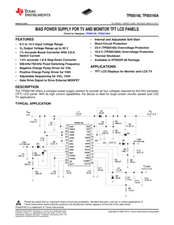
The T-CON Shield ExamplesThe T-CON is covered by a Heat Sink Shield which is responsible for relieving the heat build up on theT-CON’s DC to DC Converters and to prevent high frequency noise from exiting the T-CON as well asprevent ingress (External Radiation) from outside sources.In the examples below take note about how many LVDS cables attach to the T-CON board. This willindicate weather it’s a 60Hz or at least a 120Hz T-CON. The LVDS cable will be explained later.Some models do not have a T-CON, it’s built into the Main board. 42LE5500, 42LH40.Example 37LK450 (60Hz)Example 42LH20 (60Hz)LVDSLVDSExample 42LG70 (120Hz)Example 37LH55 (120Hz)Example 55LX6500 (240Hz)LVDS3D (2010)LVDS LVDSP-DIM LVDS LVDSBe First, Do it Right, Work Smart!4March 2012 LCD T-CON Troubleshooting
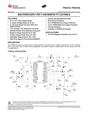
T-CON Shield Purpose and Key PointsThe T-CON shield may serve two functions.1) They prevent RF radiation, either in or out.2) Thk as a hi ti shield.hi ldThey workheatt didissipationChocolateHere are some key points to remember whenremoving the shield;o Manyoff thea pieceoff materialMth shieldshi ld havehit i lthat is used to transfer heat from acomponent on the board to the shield. Thismaterial is called “Chocolate”. Look for itwhen removing the shield. Make sure toreturn it to the correct location whenreplacing the shield. In the example on theright, the two pieces of chocolate areprotecting the DC-to-DC converter coils inthe lower right hand corner.o Always remember to put the screws backinto place on the T-CON board when theshield is removed. This will protect the smalldevices called EMI filters protecting groundreturn on the two ground pads beneath thescrews. (See example of FL6 on the right).o There is another EMI filter FL7 on thethe rightg Groundingg screw ppad.Be First, Do it Right, Work Smart!FL6EMIFilterExample from 37LH555March 2012 LCD T-CON Troubleshooting
2) WHAT IS A T-CON?1) The TT-CONCON Heat Sink ShieldShield. [Pg 3]2) What is a T-CON, (TFT Controller)? [Pg 6]3) What Voltage source does the T-CON use? [Pg 8]4) What Voltages does the T-CON generate? [Pg 10]5) What is an LVDS Cable (Low Voltage Differential Signal)? [Pg 12]6) What is the Difference between a TT-CONCON and a 3D FRC TT-CON?CON? [Pg 17]7) How to Troubleshoot a T-CON board. [Pg 20]8) Some T-CONs Route the P-DIM (Dimming Signals) to the Inverter. [Pg 31]9)) What is the ppurposepof the Blue LED on some T-CONs? [[Pgg 36]]Be First, Do it Right, Work Smart!6March 2012 LCD T-CON Troubleshooting
What is the T-CON Function?The T-CON (TFT Controller) is responsible for;1. Driving the TFT panel. This is usually accomplished by two LVDS type cables between the T-CON andth PthePanel.l ThThe panell cellll structuret tiis bbrokenk iintot VVerticalti l columnslanddHHorizontalit l rows. Horizontal Resolution: On a panel with a resolution of 1920 X 1080 we must have 1920 X 3columns, because a pixel is comprised on a Red, Green and Blue cell. So there will be 5760individual cells in rows across the screen. To turn these cells on and off, the panel will use verticaly a small board located inside the ppanel. In this wayy we can turnaddress lines or electrodes driven bythe colors on and off accordingly to recreate the correct colors required to recreate the image. Vertical Resolution: On a panel with a resolution of 1920 X 1080 there will be 1080 horizontal rowsof cells running across the panel. These rows are being driven by a small board inside the panel. Byaddressing a particular cell via the vertical columns and turning on a row of cells, only the cellsbeing address by the vertical electrodes will be activatedactivated. The number of horizontal rows determinethe panels Vertical resolution.2. TFT: Each cell has is driven by a thin film transistor called (TFT) and a capacitor. When that cells isaddressed (turned on) the capacitor will charge and will remain charged until the next refresh cycle.Generally speaking, when the cell has no power applied, it blocks the light from passing through,when it turns on, dependant upon how long it is on, allows more or less light to pass. In this way wecan control the brightness level being output by that cell.Panel Voltages: The T-CON is responsible for developing panel voltages. These voltage will varydependant upon the type of panel utilized.utilized We generally state there will be 4 voltages that are always beingdelivered to the panel, -5V, 3.3V, 16V and 26V. However, there may be more according to the type of panelbeing used.Backlights: Since the Liquid crystal panel does not generate any light of its own, there must be a lightsource behind the panel. This light source is called the “Backlights” called B\L here after. The B\L can beeither florescent (EEFL or CCFL) or they can be LED. The T-CON is not responsible for turning on the B\L.Be First, Do it Right, Work Smart!7March 2012 LCD T-CON Troubleshooting
3) WHAT VOLTAGE SOURCE DOES THE T-CON USE?1) The TT-CONCON Heat Sink ShieldShield. [Pg 3]2) What is a T-CON, (TFT Controller)? [Pg 6]3) What Voltage source does the T-CON use? [Pg 8]4) What Voltages does the T-CON generate? [Pg 10]5) What is an LVDS Cable (Low Voltage Differential Signal)? [Pg 12]6) What is the Difference between a TT-CONCON and a 3D FRC TT-CON?CON? [Pg 17]7) How to Troubleshoot a T-CON board. [Pg 20]8) Some T-CONs Route the P-DIM (Dimming Signals) to the Inverter. [Pg 31]9)) What is the ppurposepof the Blue LED on some T-CONs? [[Pgg 36]]Be First, Do it Right, Work Smart!8March 2012 LCD T-CON Troubleshooting
Understanding the Voltage Source for the T-CON .The T-CON Voltage Source will always be provided from the Main board. However, the Main board does notactually generate the T-CON source voltage. All the Main board does is switch on and off the voltage comingffromtheth PowerPSupply.SlThe Power Supply generates a 12V supply that is sent to the Main board. When it is time to turn on theT-CON, the Microprocessor will send out a command that turns on the T-CON 12V and this voltage is routedg section for more details about the T-CON 12Vout the LVDS cable to the T-CON. ((See the Troubleshootingturn on circuit).T-CONT-CON12VPowerSupply12VBe First, Do it Right, Work Smart!9MainBoardMarch 2012 LCD T-CON Troubleshooting
4) WHAT VOLTAGE DOES THE T-CON GENERATE?1) The TT-CONCON Heat Sink ShieldShield. [Pg 3]2) What is a T-CON, (TFT Controller)? [Pg 6]3) What Voltage source does the T-CON use? [Pg 8]4) What Voltages does the T-CON generate? [Pg 10]5) What is an LVDS Cable (Low Voltage Differential Signal)? [Pg 12]6) What is the Difference between a TT-CONCON and a 3D FRC TT-CON?CON? [Pg 17]7) How to Troubleshoot a T-CON board. [Pg 20]8) Some T-CONs Route the P-DIM (Dimming Signals) to the Inverter. [Pg 31]9)) What is the ppurposepof the Blue LED on some T-CONs? [[Pgg 36]]Be First, Do it Right, Work Smart!10March 2012 LCD T-CON Troubleshooting
Understanding the Voltages that the T-CON Generates.When the T-CON receives the 12V from the Main board, it turns on DC-to-DC converters on the T-CONboard to generate several voltages. Some are used on the T-CON board itself (3.3V and 1.0V) and someare sentt outt tot theth panell forf theth panel’sl’ internali tlhhorizontalit l andd verticalti l ddrivingi i bboards.d GGenerallyll speaking,kithere are 4 primary voltages sent to the panel. They are -5V, 3.3V, 16V and 26V. It is important to alwayscheck for these voltages if you having problems with the T-CON board. But always remember there may bemore voltages generated and sent to the panel on different types of panels.TFT PANELT-CONT-CONTCON12VPowerPSupply12VBe First, Do it Right, Work Smart!11If there are two LVDS cables betweenth TtheT-CONCON andd theth MainM i board,b d theth 2ndLVDS will not carry any voltages.It will also have fewer pins.MainBoardT-CON 12V switch onin the 2nd step of theturn-on process.processMarch 2012 LCD T-CON Troubleshooting
5) WHAT IS AN LVDS CABLE?1) The TT-CONCON Heat Sink ShieldShield. [Pg 3]2) What is a T-CON, (TFT Controller)? [Pg 6]3) What Voltage source does the T-CON use? [Pg 8]4) What Voltages does the T-CON generate? [Pg 10]5) What is an LVDS Cable (Low Voltage Differential Signal)? [Pg 12]6) What is the Difference between a TT-CONCON and a 3D FRC TT-CON?CON? [Pg 17]7) How to Troubleshoot a T-CON board. [Pg 20]8) Some T-CONs Route the P-DIM (Dimming Signals) to the Inverter. [Pg 31]9)) What is the ppurposepof the Blue LED on some T-CONs? [[Pgg 36]]Be First, Do it Right, Work Smart!12March 2012 LCD T-CON Troubleshooting
Understanding the LVDS Cable.The picture below shows the LVDS cables being routed from the Main board to the T-CON.LVDSLVDSExample: 37LH55Be First, Do it Right, Work Smart!13March 2012 LCD T-CON Troubleshooting
Understanding the LVDS Cable.The LVDS (Low Voltage Differential Signal) Cable in a LCD TV is responsible for two primary jobs.1. VIDEO and TIMING SIGNALS: To deliver video signalsgthat have been pprocessed into apositive and a negative going pair of signals. These pair of signals are sent is groups whichequal the resolution characteristics of the panel. As an example if the panel is a HD panel, thedifferential pair will be 10 lines carrying positive and negative going video data. And there will betwo line carrying positive and negative going clock signals. If the panel is a full HD panel, it willhave double the amount of lineslines.The positive going signals will be designated on the schematic with the suffix of (P or ) and thenegative going lines will be designated as (N or -). If you take one pare of video signals and lookat them on a scope, they will be and exact mirror of each other. One going positive and onegoing negative. By using a differential pair, the circuitry can isolate and remove the noise on theline by addition and it can extract the actual signal by subtraction which will double the signallevel.2. T-CON VOLTAGE: The T-CON board needs voltage to operate, the LVDS cable will deliver theT-CON’s operational voltage.If theth LVDS cablebl isi suspectedt d off havingh i a problem,blmostt oftenft iis can bbe seen visually.ill LLookk ffor ththecable being bent which cause the internal paths to be broken. The cable can be cut, or cracked orphysically damaged in some way. The other problem that the LVDS cable can have is the continuitycontacts that are on the side that goes into the connector can separate from the cable itself. This cany unlockingg the cable connector and removingg the cable. Then flippingpp g the cable over soonlyy be seen bythe contacts points can be seen. See if they are separated from the cable. They could be curled up oreven bent over and pressed onto another line causing a short. One other thing to look for is the cablebeing incorrectly inserted into the connector, (improperly seated).When the LVDS cable is causing a problem, the symptom can be many. Lines in the picture, portionsbl k d out,blockedt every otherth lineli missing,i inoisei patterstton theth screen, missingi i 12V tto ththe TT-CONCON causingia black or no picture symptom, etc It can even shut the TV down if the 12V is shorted.Be First, Do it Right, Work Smart!14March 2012 LCD T-CON Troubleshooting
Types of LVDS Cable ConnectorsThe LVDS cable can use different types of connections to the Main board and to the T-CON.Below shows some of the typesyp of LVDS cable connections beingg used in LG LCD TVs.To unlock, press inon the two sidesTo unlock,unlock press inon the two sidesTo unlock, press inon the two sidesTo unlock, flip down theblack locking tabTo unlock, flip up theblack locking tabTo unlock, press down torelease the locking tabThis is a wire type LVDSand not a ribbon cable type.Be First, Do it Right, Work Smart!15DEFECTIVE LVDS CABLEMarch 2012 LCD T-CON Troubleshooting
Example of LVDS Connector ContentsP802 LVDS Connector "T-CON/3D Board“ to P7800 "Main"Example from ndGndGnd24RRXA4-1.26V1.67V23D Sync Out0.03V2.34V25RRXA4 1.08V1.67V3*V SYNC3.33V1V26GndGndGnd4SDA3 3.3V3.34V1.73V27n/cn/cn/c5SCL3 3.3V3.34V1.73V28RRXB0-1.19V1.67V6FRC RESET3.32VOpen29RRXB0 1RRXB1 1.16V1.67V93D DIM3D DIM0VOpen32RRXB2RRXB2-1 2V1.2V1 67V1.67V103D DIM 20.05VOpen33RRXB2 35RRXBCK-1.16V1.67V13RRXA0 1.19V1.67V36RRXBCK 1.2V1.67V14RRXA1-1.19V1.67V37GndGndGnd15RRXA1 XB3 1.14V1.67V17RRXA2 1.14V1.67V40RRXB4-1.26V1.67V18GndGndGnd41RRXB4 K 1.20V1.67V47n/cn/cn/c21GndGndGnd48-51PANEL VCC11.59VOpen22RRXA3-1.20V1.67V23RRXA3 1.14V1.67VBe First, Do it Right, Work Smart!P8021T-CON/3D12VText in Blue are LVDSvideo signals.*Pin 23.5V p/p 60 Hz3D-Sync*Pin 2 Only active when a 3Dsource is played. (1.63V)T-CON/3D B Diode Check taken with meter in Diode Mode with all Connectors RemovedMarch 2012 LCD T-CON Troubleshooting
6) DIFFERENCE BETWEEN A T-CON AND A 3D T-CON?1) The TT-CONCON Heat Sink ShieldShield. [Pg 3]2) What is a T-CON, (TFT Controller)? [Pg 6]3) What Voltage source does the T-CON use? [Pg 8]4) What Voltages does the T-CON generate? [Pg 10]5) What is an LVDS Cable (Low Voltage Differential Signal)? [Pg 12]6) What is the Difference between a TT-CONCON and a 3D FRC TT-CON?CON? [Pg 17]7) How to Troubleshoot a T-CON board. [Pg 20]8) Some T-CONs Route the P-DIM (Dimming Signals) to the Inverter. [Pg 31]9)) What is the ppurposepof the Blue LED on some T-CONs? [[Pgg 36]]Be First, Do it Right, Work Smart!17March 2012 LCD T-CON Troubleshooting
Differences between a T-CON and a 3D FRC T-CONThe typical T-CON’s basic responsibilities are todrive the TFT panel and to generate panel voltages.The video input through the LVDS cables is alreadyformatted for usage by the T-CON board.3D FRC T-CONTypical T-CONThe 3D FRC T-CON basic responsibilities are to;generate panel voltages. When not in 3D itgenerates the Tru-Motion motion estimated motioncompensatedWhent d (MEMC) frames.fWh ini 3D itunpacks 3D frame content. It generates 3D syncwhich is used by the 3D Shutter glasses. It formatsthe video for usage by the panel driver circuit and itpanel. The video inputp throughg the LVDSdrives the pcables is 24 bit LVDS video.Be First, Do it Right, Work Smart!18Since the 3D FRC T-CON does so much morework than a standard T-CON, it has anadditional 12V input via a two wire connector.The voltage is from the same source as at i l T-CON.typicalT CON It comes fromftheth power supplyland switched on/off by the Main board.March 2012 LCD T-CON Troubleshooting
Differences between a T-CON and a 3D FRC T-CONP803 P804P802P101 n/cExample from LX6500, LX9500 seriesThis shows the location of the additionalcircuitry on the 3D FRC T-CON.FRCTru-MotionThe 12V is sent to the T-CON by two separateconnections. P802 and P803.P802Check pins49 51 (12V)49 51FPGAP803TFTDriverTFTDriverCheck pins1 or 2 (12V)Troubleshooting is the same for this type ofT-CON. See troubleshooting section.P806To the panelBe First, Do it Right, Work Smart!FRC: Frame Rate ConverterFPGA: Field-programmable gate arrayP80519March 2012 LCD T-CON Troubleshooting
7) HOW TO TROUBLESHOOT A T-CON ?1) The TT-CONCON Heat Sink Shield. [Pg 3]2) What is a T-CON, (TFT Controller)? [Pg 6]3) What Voltage source does the T-CON use? [Pg 8]4) What Voltages does the T-CON generate? [Pg 10]5) What is an LVDS Cable (Low Voltage Differential Signal)? [Pg 12]6) What is the Difference between a TT-CONCON and a 3D FRC TT-CON?CON? [Pg 17]7) How to Troubleshoot a T-CON board. [Pg 20]8) Some T-CONs Route the P-DIM (Dimming Signals) to the Inverter. [Pg 31]purposepof the Blue LED on some T-CONs? [[Pgg 36]]9)) What is the pBe First, Do it Right, Work Smart!20March 2012 LCD T-CON Troubleshooting
Troubleshooting a No Picture problem.When dealing with a suspected T-CON problem, the very first thing you should approach is “Does the T-CON boardhave it’s operational voltage”? TV TURN ON PROCESS: When the TV turns on, it is a 3 step process.Step 1) RLRL-ONON called (Relay On) or PWR ONPWR ON called (Power On). This turns on the power supply which turns onall the voltages that the Main board needs to operate. It also turns on the backlight B even though thebacklights will not be on at this time.The Main board needs several different voltages to operate. It needs the Stand-By voltage which is alwayspresent even if the set is not turned on. It needs what is called Video Processing voltage which is 12V. And itneeds Audio amplification voltage which can vary dependant upon the wattage output of the audio amplifier.This voltage will be either 17V or 24V. This voltage can also be used to generate Tuner voltage.Step 2) Panel CTL called (Panel Control). This will be the command that actually turns on the T-CON operationalvoltage by activating a switch that takes the 12V from the Power Supply and routes it to the T-CON boardthrough the LVDS cable.cable On a side notenote, the 2010 3D model T-CONsT CONs also have a secondary 12V supply(which comes from the same switch) and sends it to the T-CON through a two pin connector for additionalcurrent demands of the 3D T-CON. It is not the fact that the T-CON 12V current is too much for the 12Vsupply, it is that the current demand of the 3D FRC T-CON is too much for the thin wire in the LVDS cable.Step 3) INVINV ONON called (Inverter On) or DRV ONDRV ON called (Drive On)On). This command will turn on the backlightsbacklights.This output from the Main is sent back to the Power Supply to activate the backlight driver IC. If the backlightshave an external Ballast (Inverter), the INV ON line will be routed through the Power Supply to the Inverter.The same thing holds true for LED backlights which may have an internal or external Inverter.So the area of concern when dealing with a No Picture symptom is to first make sure there are backlightsbacklights. If thebacklights do not come on, you still may be able to see if the panel is working by using a flashlight and looking (atclose proximity) to the panel. Hold the flashlight close to the panel and look carefully for any movement within thepanel. You may also be able to shine the flash light through any hole in the metal shield covering the back of thepanel. If you see movement, this would indicate there is activity in the LCD panel and that you need to investigatethe problem from the backlight perspective.perspective Remember the backlights (Florescent or LED) need a power supply(24V) and the turn on command called DRV ON or INV ON.Continued on the next page.Be First, Do it Right, Work Smart!21March 2012 LCD T-CON Troubleshooting
Troubleshooting a No Picture problem, checking Power Supply voltages.If you have backlights but you have no picture, the fist step is to check the connector from the Power Supplyto the Main board. Confirm the 3 voltages, STBY voltage, 12V and 17V/24V. You can also listen for audiowhich would confirmfthat the Main board is processing audio and it has the Audio B .Here is an example of the connector (from a 55LW5600) coming from the Power Supply to the Main board.P502 "MAIN Board" Connector To P201 "SMPS Board"24VStand-By 3.5V12VPinLabelSTBYRunDiode d9-123.5V .01V2.09V20A-DIMn/cn/cOL2112V0V12 01V12.01V2 09V2.09V22PDIM-10V0.2V 3.3V2.4V23n/cn/cn/cOL24Err OUTn/cn/cOLPWR ON Step 1:Turns on thePower Supply. 1Steps 1 and 3 of thethree step Turn OnProcess go to thePower SupplyDRV ON Step 3:Turns on the3Backlights.Note: We will discuss the 2nd step of the turn on sequence next.Be First, Do it Right, Work Smart!22March 2012 LCD T-CON Troubleshooting
No Picture problem, Checking the T-CON’s Voltage from the Main board 1 of 2During Step 2 of the Turn On sequence, Panel CTL turns on the 12V to the T-CON. Once you haveconfirmed that the Main board is receiving the correct voltages, you need to confirm that the T-CON isreceivingi i itits operationaltil voltage.ltTheTh bbestt way tto checkh k iis tto bbegini withith ththe LVDS cablebl ffrom ththe MMaini tto ththeT-CON. It will have a test point for the 12V to the T-CON. Look on the left or right side for 4 pins tiedtogether, this will be the 12V test point. In some cases when the set has two LVDS cables, look on the LVDScable with the most pins (usually 51). Then look on the left or right side for 4 pins tied together. This will bepoint. ((The LVDS cable with the fewer pinspwill not be carryingy g anyy DC voltage).g )the 12V test pTip: Some models use the first and last pin as ground. This is easy to verify with a DVM in ohms.Tip: Some models use a plug in type of connector instead of a ribbon cable. In this case you can not tell ifthe 4 pins are tied together, so with the set turned on, just measure pin 2 and/or the next to the lastpin for 12V on the LVDS connector with the most pins if there is more than one LVDS connection.12V TO THE T-CON:Here is an example of how theT-CON 12V is routed to theLVDS connector. You will notethat pins 48 through 51 arecarrying the 12V to the T-CON.In this case it is not possiblevisually to determine that thelast 4 pins are tied togethertogether.This is where you wouldmeasure the 2nd and the next tothe last pin for 12V.PANEL VCCExample from 55LW5600Be First, Do it Right, Work Smart!23March 2012 LCD T-CON Troubleshooting
No Picture problem, Checking the T-CON’s Voltage from the Main board 2 of 2During Step 2 of the Turn On sequence, Panel CTL turns on the 12V to the T-CON. For an internal look atthe circuitry involved in generating the 12V for the T-CON, look at the circuit shown in the example below.HHereiis an examplel off hhow ththe TT-CONCON 12V iis switchedit h d on/off/ ff on ththe MMaini bboard.d WhWhen ththe MiMicroprocessoroutputs Panel CTL it is routed to Q505 which turns on. The Collector current goes high and the collectorvoltage goes low. This drops the base of Q506 low and Q506 turns off. This allows the 12V from the PowerSupply routed through L511 to pull up the Gate of Q507 via R558. Q507 has the 12V on its Source.Q507 switches on it outputspthe 12V to the T-CON throughg the LVDS connector which was explainedpWhen Qon the previous page.Example from 55LW5600PANEL VCC12V from thePower Supply12VHighLowPANEL CTLFrom Micro.HighgBe First, Do it Right, Work Smart!24March 2012 LCD T-CON Troubleshooting
No Picture problem, Checking the T-CON’s VoltageOnce you have confirmed that there is 12V on the Main board side of the LVDS connector, it is time to get tothe T-CON itself. Since the T-CON is generally covered by a shield, you may or may not be able to get to the12V TP withoutith t removingi ththe shield.hi ld(Note: Review Section 1 which details different types of T-CON Shields).There will always be a 12V fuse protection the 12V line. It will always be the first component the 12V passesy test pointpto check for the 12V inputp to the T-CON. If it is here,,once it enters the T-CON. So this is an easyyou can continue. If it is missing, check the LVDS cable for an open from the Main to the T-CON. Be sure(with the power turned off) to remove the LVDS cable from the connectors on both ends to investigate forfrayed contacts. This most often happens on the LVDS cablesthat are slipped into the connector and theExample fromConnector has a flip locking42LV5500mechanism.LVDS with themost pinsT-CON from42LV550012V FuseF1T CON fromT-CONf42LV5500Be First, Do it Right, Work Smart!25March 2012 LCD T-CON Troubleshooting
No Picture problem, Checking the T-CON’s DC to DC ConverterAll T-CONs have a DC-to-DC converter which develops voltages for the T-CON board itself and for thepanel. Some have more than one. It is important to check these voltages once the 12V input has beenconfirmed.fid ToT locatelt theth maini DCDC-to-DCt DC converter,t lookl k forf theth largerlcoilsil on ththe bboard.d IIn ththe examplelbelow, the two larger coils can easily be seen on the upper left hand side. The flat pack IC US1 is the mainDC-to-DC converter driver IC. If you do not have any training material you can still pick out some keyvoltage source TPs from the DC-to-DC converter. Look for “VCC, VDD, HVDD, VGL or VGH” silk screenedlabels on the board.This T-CON actually has more than oneDC-to-DC converter.See the next page for greaterdetails.Example from 42LV5500US1VCCSilkScreenLabelThe left coil L1 is filtering the 12V input to theDC-to-DC converter.The right hand coil L2 is filtering VCC which is 3.3VBe First, Do it Right, Work Smart!26March 2012 LCD T-CON Troubleshooting
No Picture problem, Checking the T-CON’s DC to DC ConverterExample from 42LV5500Be First, Do it Right, Work Smart!27March 2012 LCD T-CON Troubleshooting
Checking a 3D FRC T-CON’s DC to DC ConverterExample from 42LV5500IC600DC-to-DCConverterExamplep fromLX9500 seriesBe First, Do it Right, Work Smart!28March 2012 LCD T-CON Troubleshooting
No Picture problem, Running the Panel Test 1 of 2When there is a video problem it can be difficult to determine if the problem is related to the Mainboard, the T-CON board or the Panel. Most of the typical T-CON boards (not the 3D FRC T-CONs)have a built in test pattern that can be run to isolate the problem.The next page gives the details about how to set up the T-CON board so that it can run the PanelTest.Al rememberAlsob thatth t tot run theth PanelPlTTest;t The Power Supply must be working normally. The Backlights must be running normally.This test can also be used when there is video but the video has a problemproblem.If there is a Video Problem and the Panel Test works normally, before condemning the Main boardbe sure to investigate the LVDS cable.Sum Upp the Panel Test:The LVDS cables must be removed before running the test.12V must be jumped to the T-CON.3.3V must be jumped to pin 41 of the LVDS cable on the 51 pins LVDS.The Power Supply must be OK.Th BTheBacklightskli h must bbe OKOK.Side note: If the Power Supply is not working, you can still run the Backlights and the Panel Test bysubstituting;24V and DRV ONDRV ON (usually 33.5V 5V)5V 5V) to the Inverter (Ballast).(Ballast)12V and 3.3V to the T-CON as described above.Be First, Do it Right, Work Smart!29March 2012 LCD T-CON Troubleshooting
T-CON (TFT Drive) Board Panel Test 2 of 2Set up the Power Supply so that it can run without the Main board if the Main board will not turn on thePower Supply. Do not apply AC at this time.3 JumpJ12V fromftheth SMPS tot theth T-CONT CON FuseF124Disconnect bothLVDSS CabCablesesJump 3.3V from the VCCTP to pin 44 of CN15Apply AC to the Power Supply and Toggling patterns ofWhite, Red, Blue, Green should appear on the screenBe First, Do it Right, Work Smart!March 2012 LCD T-CON Troubleshooting
8) P-DIM ROUTED THROUGH THE T-CON1) The T-CONT CON Heat Sink ShieldShield. [Pg 3]2) What is a T-CON, (TFT Controller)? [Pg 6]3) What Voltage source does the T-CON use? [Pg 8]4)) What Voltagesg does the T-CON ggenerate? [Pg[ g 10]]5) What is an LVDS Cable (Low Voltage Differential Signal)? [Pg 12]6) What is the Difference between a T-CON and a 3D FRC T-CON? [Pg 17]7) How to Troubleshoot a T-CON board. [Pg 20]8) Some T-CONs Route the P-DIM (Dimming Signals) to the Inverter. [Pg 31]9) What is the purpose of the Blue LED on some T-CONs? [Pg 36]Be First, Do it Right, Work Smart!31March 2012 LCD T-CON Troubleshooting
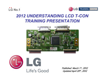
Some T-CONs Deliver P-DIM (Dimming Signals) to the InverterP-DIM (Called PWM-DIM which stands for Pulse Width Modulation Dimming) is a signal from the Mainboard that is generated by monitoring the Video content’s average brightness level. It is then sent to theB kli ht dBacklightdriveriIC tto controlt l ththe bbrightnessi htoff ththe bbacklightskli ht accordingly.di l ThThe maximumibbrightnessi htllevell iisestablished by the customer through the Customer’s Menu in the Video selection under Backlights. Thissetting has a bar graph that can be set from 100% down to 0%.The P-DIM signal will follow the percentile setting proportionately. The range of P-DIM is 3.3V to 0V. Sographp is set for 100%% the P-DIM line will be 3.3V and the backlightg brightnessgwill bewhen the bar gmaximum.Most often the P-DIM line is routed directly from the Main board to the Power Supply, it is routed through thePower Supply directly to the Inverter and then to the Backlight driver IC.(If the Power Supply has an on-board Inverter, the Driver IC is on the Power Supply itself).However on some sets,However,sets the PP-DIMDIM line is routed to the TT-CONCON board.board The TT-CONCON then generates a
The Power Supply generates a 12V supply that is sent to the Main board. When it is time to turn on the T-CON, the Microprocessor will send out a command that turns on the T-CON 12V and this voltage is routed out the LVDS cable to the T-CON. ((gSee the Troubleshooting section for more details