Transcription
US Army Corpsof EngineersAfghanistan Engineer DistrictAED Design Requirements:Water Tanks & SystemDistributionVarious Locations,AfghanistanSEPTEMBER 2009 Version 1.2
AED Design RequirementsWater Tanks & System DistributionTABLE OF CONTENTSAED DESIGN REQUIREMENTSFORWATER TANKSVARIOUS LOCATIONS,AFGHANISTANSectionPage1. General12. Water Tanks13. Distribution System Requirements14. Types of Storage55. Water Requirements76. Capacity of Water Supply System87. Storage Requirements88. Amount of Water Available Under Emergency Conditions99. Elevated Storage Capacity910. Water Distribution System Capacity Analysis1011. Shop Submittals As-Builts1112. References12FiguresFigure 1. Effects of Elevated Storage4Figure 2. Conventional Elevated Storage Tank6Figure 3. Single Pedestal Elevated Storage Tank6i
AED Design RequirementsWater Tanks & System DistributionTablesTable 1. Domestic Water Allowance7Table 2. Capacity Factors8AppendicesAppendix A Example Water Distribution Analysis13Appendix B Procedures for Leakage and Pressure Testing17ii
AED Design RequirementsWater Tanks & System Distribution1. GeneralThe purpose of this document is to provide water storage and distribution design requirements toContractors for projects at USACE-AED projects. This is a summary of design and testingrequirements for USACE-AED construction. Design procedures and examples can be found in thedocuments listed in the reference section.2. Water Tanks & Distribution SystemsWater tanks may be required where a new water distribution system is proposed or as an upgrade toan existing water distribution system. Reference 1 provides design guidance specifically for waterstorage. Storage capacity of the water tank should meet peak flow requirements, equalize systempressures, and provide emergency water supply. The water supply system must provide flows ofwater sufficient quantity to meet all points of demand in the distribution system. To do so, pressurelevels within the distribution system must be high enough to provide suitable pressure, and waterdistribution mains must be large enough to carry these flows. Reference 2 provides design guidancespecifically for water distribution. Water storage facilities are constructed within a distribution networkto meet the peak flow requirements exerted on the system and to provide emergency storage. Watersupply systems must be designed to satisfy maximum anticipated water demands. The peakdemands usually occur on hot, dry, and summer days when larger than normal amounts of water areused for irrigation and washing vehicles and equipment. In addition, most industrial processes,especially those requiring supplies of cooling water, experience greater evaporation on hot days, thusrequiring more water. The necessary storage can be provided in elevated, ground, or a combinationof both types of storage. Requirements for storage are discussed further in Section 7.3. Water Distribution System RequirementsThe Contractor shall install water distribution mains, branches, laterals, lines and service connectionsto include all pipe, valves, fittings and appurtenances, and pipe thrust restraint. Exterior water lineconstruction shall include service to all buildings as described in the contract Scope of Work Section01010. Distribution system designs must consider system operating pressure range; the pipe sizeand material, including joint construction and fittings; disinfection, and construction testing.Pipe material is of importance from the standpoint of constructability, service life, and ease ofmaintenance. In USACE-AED projects PVC Schedule 80 pipe is the preferred material. This pipehas well documented experience in previous projects; it has superior strength and durability of overtime to other thermoplastic pipe material, it is easily repaired, and materials including fittings arereadily available in Afghanistan.a) System Pressure Requirements.Distribution systems shall provide system pressures that are neither too low 70 KPa (10 psi) foroperating plumbing fixtures nor too high such that they are damaged. Pressure are measured at thebuilding service connection; therefore pressures at this location must be generally in excess of 207KPa (30 psi) for one to two story buildings considering internal pipe friction head losses.1) Minimum pressures. Water distribution system, including pumping facilities and storagetanks or reservoirs, should be designed so that water pressures of at least 275 KPa (40 psi)at ground level will be maintained at all points in the system, including the highest groundelevations in the service area. Minimum pressures of 207 KPa (30 psi) under peak fixtureflow conditions can be tolerated at the building farthest from the water source (tank or boosterpump) as long as all peak fixture flow requirements can be satisfied at all locations. Duringfirefighting flows, water pressures should not fall below 138 KPa (20 psi) at the hydrants, innew systems. Fire fighting capability is provided using hose streams at only a limited numberof projects as specified in the contract.1
AED Design RequirementsWater Tanks & System Distribution2) Maximum pressure. Maximum water pressures in distribution mains and service linesshould not normally exceed 517 KPa (75 psi) at ground elevation. Higher pressures requirepressure reducing valves on feeder mains or individual service lines to restrict maximumservice pressures to 517 KPa (75 psi).3) Multiple pressure levels. If an extensive area has pressures higher than 517 KPa (75 psi)lower than 275 KPa (40 psi) under a single pressure level zone, it may be appropriate todivide the system into two or more separate zones, each having different pressure levels.Within each level, pressures within the distribution system should range from 275 KPa to 517KPa (40 to 75 psi) at ground elevation.b) Pipe Size and Material.Pipe diameter is related to the design of adequate system pressure because the larger the pipediameter the lower the friction head loss and therefore more service pressure availability. In addition,USACE water system planning technical criteria recognize good engineering judgment includesproviding some safety factor in the design. The contract’s minimum size is desirable for future growththat the contractor cannot account for in their analysis, and their water distribution analysis cannot beverified until after construction; and even then at great effort. Water system models do not accountfor all system losses and operational circumstances. Furthermore, sizing water mains for the bareminimum when new means the system will be under sized as it ages in the future when pipe leaksand scale occur and other components such as valves and flow meters deteriorate. Unnecessarilysmall water main pipe diameters increase the booster pump horsepower requirements, energy costsfor operation, and ultimately make water system sustainability more of an issue.1) Pipe diameters and velocities. The minimum pipe diameter in the distribution system shallbe 100mm (4 inch). The maximum velocity shall be 5 feet per second (1.5 meters persecond) at 150% of the fixture unit flow or 2 times the average daily flow (8-hour basis),whichever is greater. The Contractor shall provide a water distribution system described asfollows: Pipe diameters used in the network shall be 100mm or greater, as required tomaintain proper system velocities and pressures between 275 KPa (40 psi) and 275 KPa (75psi). Pipes for building service connections may be smaller diameter and shall be sizedbased on the fixture unit flows required for each building.2) Pipe materials. The Contractor shall provide pipe of adequate strength, durability and becorrosion resistant with no adverse effect on water quality. Water distribution pipe materialshall be PVC or Ductile Iron (DI). Ductile iron pipe shall conform to AWWA C104. DI fittingsshall be suitable for 1.03MPa (150psi) pressure unless otherwise specified. Fittings formechanical joint pipe shall conform to AWWA C110. The exterior surface of the pipe must becorrosion resistant. If DI pipe is installed underground pipe shall be encased withpolyethylene in accordance with AWWA C105. Fittings and specials shall be cement mortarlined (standard thickness) in accordance with C104. Fittings for use with push-on joint pipeshall conform to AWWA C110 and C111. Polyvinyl Chloride (PVC) pipe shall conform toASTM D 1785. Plastic pipe coupling and fittings shall be manufactured of materialconforming to ASTM D 1784, Class 12454B. PVC screw joint shall be in accordance withASTM D 1785 Schedules 80 and 120. PVC pipe couplings and fittings shall be manufacturedof material conforming to ASTM D 1784, Class 12454B. Pipe for building service, less than80mm (3 inch) may be screw joint and shall conform to dimensional requirements of ASTM Dschedule 80. Elastomeric gasket-joint, shall conform to dimensional requirements of ASTM D1785 Schedule 80, All pipe and joints shall be capable of 1.03 MPa (150psi) workingpressure and 1.38 MPa (200psi) hydrostatic test pressure.The only time HDPE and PVCu will be allowed in any AED project, including facility designs,water transmission pipelines, sewer force mains and non pressure pipe applications such asstorm water or gravity sewers, is through an approved variation request submitted inaccordance with Section 01335 of the contract. The variation request shall be submitted to2
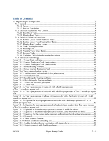
AED Design RequirementsWater Tanks & System DistributionAED Engineering for approval. PVCu pipe material shall be specifically manufactured inaccordance with specifications and labeled as Schedule 80 pipe according to ASTM D1785specifications. Variation request shall include (among other items stated in Section 013353.6.4) the pipe material cell classification used in the product, the standard dimension ratio(SDR), the type of jointing being used, and the proposed use for the product (such as wellcasing or water distribution pipe lines). To be considered for a variation, HDPE pipe shallconform to Deutsche Institut fur Normung (DIN) 8074 Polyethylene Pipe - Dimensions andDIN 8075 Polyethylene Pipes – General quality requirements and testing (August 1999).Installation shall be as specified in AWAA M55 PE Pipe – Design and Installation. In theabsence of products or installation methods not meeting these standards, the contractor shallprovide documentation using the variations process in the contract section 01335 forapproval prior to installation.c) Pressure Provisions.1) Elevated storage. Within the distribution system, elevated storage permits the wellpumping to a tank to operate at uniform rates and without frequent start/stop cycles. Theusefulness of elevated storage is shown in Figure 1. The system illustrated in Figure 1 (A)(without elevated storage) requires storage at the plant sufficient to provide for systemdemand rates in excess of the plant production rate, assuming the plant is operated at a uniform rate. The pump station forces water into the service main, through which it is carried tothree load areas: A, B, and C. Since all loads on the system are met without the use ofelevated storage, the pump station must be capable of supplying the peak rates of water useto Areas A, B, and C, simultaneously, while maintaining the water pressure to Area C at asufficient level. The minimum recommended pressure in the distribution system under nonpeak nonemergency flow conditions is 275 KPa (40 psi). Figure l (B) assumes the construction of an elevated storage tank on the service main between Areas B and C, with peak loadsin Area C and part of the peak load in Area B being satisfied from this tank. The elevation ofthe tank ensures adequate pressures within the system. The storage in the tank isreplenished when water demands are low and the well (or pump station in the figure) can fillthe tank while still meeting all flow and pressure requirements in the system. The Figure 1 (B)arrangement reduces required capacity of the booster pumps.2) Booster pump pressure. Booster pump stations are sited downstream of ground levelwater tanks in order to provide the system operating pressure. Therefore they operate at theposition shown in Figure 1A except that the pump total dynamic head (TDH) must besufficient at the pump discharge to elevate the system pressure above the minimum pressurerequirement at every location in the water system. Therefore compared to systems that haveelevated storage, there is less uniformity in the system pressure and generally greater energyused to maintain system pressure than in a centrally located water tank. Booster pumpingapplications within AED shall have either a bladder style expansion or a hydropneumatictank.3) Most elevated storage tanks “float” on the distribution system. That is, the elevated tank ishydraulically connected to the distribution system, and the volume of water in the tank tendsto maintain system pressures at a uniform level. When water use is high and boosterpumping facilities cannot maintain adequate pressures, water is discharged from elevatedtanks. Conversely, when water use is low, the booster pumps, which operate within areasonably uniform head-capacity range, supply excess water to the system and the elevatedstorage is refilled. This condition is not normally encountered in designs in Afghanistan sinceit assumes that the booster pumps draw water from a source other than the elevated tankbeing filled.3
AED Design RequirementsWater Tanks & System DistributionFigure 1. Effects of Elevated Storaged) Valves and Thrust Restraint1) System Isolation Valves. Valves (Gate valves w/box) shall be placed at all pipe networktees and cross intersections, and the number of valves shall be one less than the numberof lines leading into and away from the intersection. For isolation purposes, valves shallbe spaced not to exceed 3600 mm (12 feet) from tees or crosses. Gate valves shall be inaccordance with AWWA C 500 and/or C509. Butterfly valves (rubber seated) shall be inaccordance with C504. The valves and valve boxes shall be constructed to allow a4
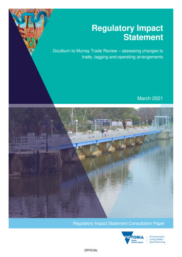
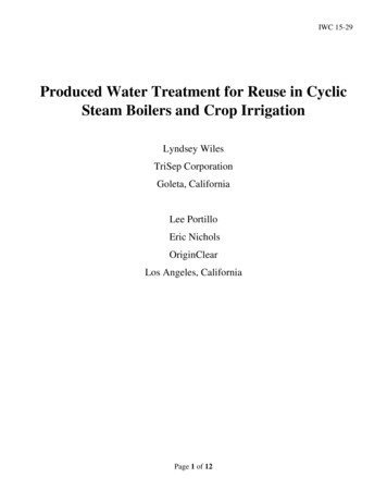
AED Design RequirementsWater Tanks & System Distributionnormal valve key to be readily used to open or close the valve. Provide traffic-rated valveboxes and concrete pad, 1 meter (3’-4”) square, for all valve boxes.2) Air Release Valves. Air release valves are required to evacuate air from the main highpoints in the line when it is filled with water, and to allow the discharge of air accumulatedunder pressure. Vacuum relief valves are needed to permit air to enter a line when it isbeing emptied of water or subjected to vacuum. Contractor shall submit manufacturer’sdata for properly sized combination air and vacuum release valves and determine theirlocations on the distribution system subject to review and approval of the ContractingOfficer.3) Blow-off Valves. The Contractor shall provide 40-50mm (1-5/8” – 2”) blow-offvalves at ends of dead end mains. Valves should be installed at low points in themains where the flushing water can be readily discharged to natural or manmadedrainage ditches, swales or other.Thrust restraint is required for pipe diameters 100 mm in diameter or larger. Restraint may beachieved by the type of joint system selected or by thrust blocking.4. Types of StorageRequired storage capacity at military installations is met by use of elevated or ground storage.Examples of standard water tank construction at USACE-AED projects are shown in Figures 2 and 3.Elevated storage, feeds the water distribution system by gravity flow. Storage which must be pumpedinto the system is generally in ground storage tanks. Clear-well storage, which is usually part of awater treatment plant, is not included in computing storage unless sufficient firm pumping capacity isprovided to assure that the storage can be utilized under emergency conditions, and then only to theextent of storage in excess of the 24-hour requirements of the treatment plant. Clear-well storage isused to supply peak water demand rates in excess of the production rate, and to provide a reservoirfor plant use, filter backwash supply, and water supply to the system for short periods when plantproduction is stopped because of failure or replacement of some component or unit of treatment.a) Ground Storage. Ground storage is usually located remote from the treatment plant (if one exists)but within the distribution system. Ground storage is used to reduce well or treatment plant peakproduction rates and also as a source of supply for re-pumping to a higher pressure level. Suchstorage for re-pumping is common in distribution systems covering a large area, because the outlyingservice areas are beyond the range of the primary pumping facilities. An example of a ground levelreinforced concrete tank at USACE-AED projects is given in Figure 2. Ground level water tanks maybe either reinforced concrete or steel construction. Ground storage tanks or reservoirs, belowground, partially below ground, or constructed above ground level in the distribution system, may beaccompanied by pump stations if not built at elevations providing the required system pressure bygravity. There are a few projects in the USACE-AED project inventory that have partially belowground-level tanks. However, if the terrain permits, the design location of ground tanks at anelevation sufficient for gravity flow is preferred. Concrete reservoirs are generally built no deeperthan 6.1-7.6 meters (20-25 feet) below ground surface. If rock is present, it is usually economical toconstruct the storage facility above the rock level. In a single pressure level system, ground storagetanks should be located in the areas having the lowest system pressures during periods of high wateruse. In multiple pressure level systems, ground storage tanks are usually located at the interfacebetween pressure zones with water from the lower pressure zones filling the tanks and being passedto higher pressure zones through adjacent pump stations.b) Elevated Storage. Elevated storage is provided within the distribution system to supply peakdemand flow rates and equalize system pressures. In general, elevated storage is more effective andeconomical than ground storage because of the reduced pumping requirements, and the storage canalso serve as a source of emergency supply since system pressure requirements can still be mettemporarily when pumps are out of service. The most common types of elevated storage areelevated steel tanks, and standpipes. An example of an elevated steel tank at USACE-AED projectsis given in Figure 3. Elevated storage tanks should be located in the areas having the lowest system5
AED Design RequirementsWater Tanks & System Distributionpressures during intervals of high water use to be effective in maintaining adequate system pressuresand flows during periods of peak water demand. These are those of greatest water demand or thosefarthest from pump stations. Elevated tanks are generally located at some distance from the pumpstation serving a distribution pressure level, but not outside the boundaries of the service area, unlessthe facility can be placed on a nearby hill. Additional considerations for locating elevated storage areconditions of terrain, suitability of subsurface soil and/or rock for foundation purposes, and hazards tolow-flying aircraft. Elevated tanks are built on the highest available ground, up to static pressures of517 KPa (75 psi) in the system, so as to minimize the required construction cost and heights.Figure 2. Ground Level Storage TankProvide externallevel indicatorFigure 3. Standard Elevated Storage Tank6
AED Design RequirementsWater Tanks & System Distribution5. Water RequirementsThe design of the water distribution systems shall be sized to provide flow and discharge based on afixture unit basis or the basis of the average daily demand multiplied by the capacity factor, whicheveris the greater. This flow is to be used to design facilities on an installation and is called the AverageDaily Flow (ADF). The ADF is used to design installation water and wastewater systems and iscalculated as the effective population x ADD x CF. These terms are defined below.a) Domestic Requirements. The daily, per capita water requirements/allowances used in the designof facilities in Afghanistan are derived from Table 1 below unless stated differently in the contracttechnical requirements. These allowances do not include special purpose water uses, such asindustrial, aircraft-wash, air-conditioning, irrigation, or extra water demands at desert stations. Theterm Average Daily Demand (ADD) and Domestic Water Allowance are terms used to quantify thevolume of water used by an average individual at the facility being designed. These terms DO NOTinclude a capacity factor CF, described below in Table 2. If an individual ADD or water allowance isdefined in the Scope of Work or Technical Requirements, that value in the Contract shall be used fordesign calculations and not the value provided in Table 1. In either case, a capacity factor (seeParagraph 6, Table 2) should be applied when making design and sizing calculations.b) Fire-Flow Requirements. Fire flow demand will generally not be included in the sizing of waterstorage facilities except where specifically stated in the contract technical requirements. In thosecases a stand-alone water storage tank may be required in the technical requirements. In this caseonly, the system must be capable of supplying the fire flow specified plus any other demand thatcannot be reduced during the fire period at the required residual pressure and for the requiredduration. The requirements of each system must be analyzed to determine whether the capacity ofthe system is fixed by the domestic requirements, by the fire demands, or by a combination of both.Where fire-flow demands are relatively high, or required for long duration, and population and/orindustrial use is relatively low, the total required capacity will be determined by the prevailing firedemand. In some exceptional cases, this may warrant consideration of a special water system for firepurposes, separate, in part or in whole, from the domestic system. However, such separate systemswill be appropriate only under exceptional circumstances and, in general, are to be avoided.Table 1. Domestic Water Allowance/Average Daily Demand (ADD)Liters/Capita/Day (Gallons/Capita/Day)U.S. ForcesCoalition ForcesANAANP1Dining Facility2Wash RacksVehicle MaintenanceEnduringBaseContingencyBase285 (75)190 (50)155 (41)155 (41)# of meals x rate/meal# of vehicles x rate/vehicle20 (5)/vehicle190 (50)115 (30)95 (25)95 (25)# of meals x rate/meal# of vehicles x rate/vehicle20 (5)/vehicleNotes:1Rate/meal shall be 2 liters (0.5 gallons) for breakfast, 4 liters (1 gallon) for lunch and 8 liters (2gallons) for dinner.2Rate/vehicle shall be 75 liters (20 gallons) for cars small trucks, 115 liters (30 gallons) for largetrucks and 190 liters (50 gallons) for aircraft.7
AED Design RequirementsWater Tanks & System Distributionc) Irrigation Requirements. The allowances indicated in Table 1 include water for limited watering forplanted and grassed areas. However, these allowances do not include major lawn or other irrigationuses. Lawn irrigation provisions for facilities, such as family quarters and temporary structures, in allregions will be limited to hose bibs on the outside of buildings and risers for hose connections. Wheresubstantial irrigation is deemed necessary and water is available, underground sprinkler systems maybe considered. Where irrigation requirements are justified in arid or semi-arid regions, such irrigationquantities will be included as an industrial water requirement and not as a domestic requirement.6. Capacity of Water Supply SystemIn order to account for fluctuations in water use at facilities, a safety or capacity factor (CF) isintroduced into the design calculations. Capacity factors, as a function of "Effective Population" areshown in Table 2, as follows:Table 2. Capacity Factors (CF)Per the UFCs, the "Capacity Factor" will be used in planning water supplies for all projects, includinggeneral hospitals. The proper "Capacity Factor" as given in Table 2 is multiplied by the "EffectivePopulation" to obtain the "Design Population." For example, a facility with a planned (effectivepopulation) of 93 persons would be considered to have a design population of 93 x 1.5 140.Capacity factors and Design Populations will be used in calculating the ADF, capacity of the supplyworks, supply lines, treatment works, principal feeder mains and storage reservoirs. Taking this intoaccount, the required storage volume for a facility with 93 assigned personnel, would be 93 personsmultiplied by the ADD of 155 liters per person per day (Table 1), multiplied by the capacity factor (CF)of 1.5 (Table 2), which means, 93 x 155 x 1.5 21.62 cubic meters (5,710 gallons). It should bestressed again that ADD values provided in the contract documents shall be used when given, butthat capacity factors must be applied unless specifically excluded in those contract documents.When necessary, arithmetic interpolation should be used to determine the appropriate CapacityFactor for intermediate project population. (For example, for an "Effective Population" of 7,200 ininterpolation, obtain a "Capacity Factor" of 1.39.) Capacity factors will NOT be used for hotels andsimilar structures that are acquired or rented and troop housing. Capacity factors will NOT be appliedto fire flows, irrigation requirements, or industrial demands.7. Storage RequirementsThe amount of water storage provided will conform to the requirements set forth herein. Storagerequirements for MILCON projects are explained in Reference 1. Requirements for ANP and ANAvary, but are typically a minimum provision of one (1) day average daily flow which is the ADDmultiplied by the effective population (c) multiplied by the capacity factor (ADD x c x CF). In allprojects, the storage requirements stated in the contract technical requirements (Section 01015) shallbe multiplied by the capacity factor unless specifically stated otherwise.In general for MILCON projects, total storage capacity, including elevated and ground storage, will beprovided in an amount not less than the greatest of the following items.8
AED Design RequirementsWater Tanks & System DistributionItem 1: One hundred percent (100%) of the ADF (ADD x c x CF) plus all industrial requirements. Thiswill provide minimum operational storage needed to balance average daily peak demands on thesystem and to provide an emergency supply to accommodate essential water needs during minorsupply outages of up to a one-day duration. For the purposes of this item, essential water needs donot include the fire demand.Item 2: The fire demand is the required fire flow needed to fight a fire in the facility (including waterrequired to support fire suppression systems) which constitutes the largest requirement for any facilityserved by the water supply system; plus 50 percent of the average domestic demand rate plus anyindustrial or other demands that cannot be reduced during a fire period. This amount will be reducedby the amount of water available under emergency conditions during the period of the fire. The firedemand quantity must be maintained in storage for fire protection at all times except following a firefighting operation when the fire demand quantity would be depleted. It is recognized that during dailyperiods of peak consumption due to seasonal demands, the amount of water in storage will be lessthan full storage capacity; however, conservation methods will be instituted to prevent drawdown ofwater in storage below the fire demand quantity. Fire demand flow may not be included in theproject; check the Section 01015 technical requirements for provision of fire flow demand.8. Amount of Water Available Under Emergency Conditions.Where the water supply is obtained from wells, all of which are equipped with standby power andlocated within the distribution system, the emergency supply will be considered as the quantityavailable from all but one of the wells. Where one well has a capacity greater than the others, thatone will be assumed out of service. Where only 50 percent of the wells have standby power, theemergency supply will reconsidered as the quantity available from the wells having standby power.9. Design and Construction of Water Storage FacilitiesAll treated water reservoirs must be covered to prevent contamination by dust, birds, leaves, andinsects. These covers will be, insofar as possible, watertight at all locations except vent openings.Special attention should be directed toward making all doors and manholes watertight. Ventopenings must be protected to prevent the entry of birds and insects; and vent screens should bekept free of ice or debris so that air can enter or leave the reservoir area as temperature and waterlevels vary. All overflows or other drain lines must be designed so as to eliminate the possibility offlood waters or other contamination entering the reservoir. Reservoir covers also protect the storedwater from sunlight, thus inhibiting the growth of algae. Further prevention of algae growth orbacterial contamination, due to the depletion of the chlorine residual, can be obtained by maintainingsufficient flow through the reservoir so that water in the reservoir does not become stagnant. Minimalflows through the reservoir also help to prevent ice buildup during cold periods.All storage tanks will be provided with external level indicators to prevent overflows during filling.Depending upon the contract requirements, either level controls to the well pump motor control panelor altitude valves shall be used to control overflows of the water tank. If the contract technicalrequirements specifically state that altitude valves shall be used, these altitude valves will be installedin concrete pits havi
distribution mains must be large enough to carry these flows. Reference 2 provides design guidance specifically for water distribution. Water storage facilities are constructed within a distribution network to meet the peak flow requirements exerted on the system