Transcription
Table of Contents7.1 Organic Liquid Storage Tanks . 37.1.1 General . 37.1.1.1 Scope . 37.1.1.2 Process Description . 47.1.2 Emission Mechanisms And Control . 87.1.2.1 Fixed Roof Tanks . 87.1.2.2 Floating Roof Tanks. 97.1.3 Emission Estimation Procedures. 147.1.3.1 Routine Losses From Fixed Roof Tanks. 167.1.3.2 Routine Losses From Floating Roof Tanks . 317.1.3.3 Floating Roof Landing Losses . 387.1.3.4 Tank Cleaning Emissions. 387.1.3.5 Flashing Loss . 567.1.3.6 Variable Vapor Space Tanks. 567.1.3.7 Pressure Tanks . 577.1.3.8 Variations Of Emission Estimation Procedures . 587.1.4 Speciation Methodology . 63Figure 7.1-1. Typical fixed-roof tank. 67Figure 7.1-2. External floating roof tank (pontoon type) . 68Figure 7.1-3. External floating roof tank (double deck) . 69Figure 7.1-4. Internal floating roof tank . 70Figure 7.1-5. Domed external floating roof tank . 71Figure 7.1-6. Vapor-mounted primary seals . 72Figure 7.1-7. Liquid-mounted and mechanical shoe primary seals . 73Figure 7.1-8. Secondary rim seals. 74Figure 7.1-9. Deck fittings for floating roof tanks . 75Figure 7.1-10. Deck fittings for floating roof tanks . 76Figure 7.1-11. Slotted and unslotted guidepoles . 77Figure 7.1-12. Ladder well. 78Figure 7.1-13a. True vapor pressure of crude oils with a Reid vapor pressureof 2 to 15 pounds per square inch . 79Figure 7.1-13a. True vapor pressure of crude oils with a Reid vapor pressure of 2 to 15 pounds per squareinch. 79Figure 7.1-14a. True vapor pressure of refined petroleum stocks with a Reid vapor pressure of 1 to 20pounds per square inch. 80Figure 7.1-13b. Equation for true vapor pressure of crude oils with a Reid vapor pressure of 2 to 15pounds per square inch. 82Figure 7.1-14b. Equation for true vapor pressure of refined petroleum stocks with a Reid vapor pressureof 1 to 20 pounds per square inch . 82Figure 7.1-15. Equations to determine vapor pressure constants A and B for refined . 82Figure 7.1-16. Equations to determine vapor pressure Constants A and B for crude oil stocks . 83Figure 7.1-17. Equations for the average daily maximum and minimum liquid surface temperatures . 83Figure 7.1-18. Reserved. . 84Figure 7.1-19. Vapor pressure function . 85Figure 7.1-20. Bottom conditions for landing loss . 86Figure 7.1-21. Ladder-slotted guidepole combination with ladder sleeve . 86Figure 7.1-22. Slotted-guidepole with flexible enclosure . 8706/2020Liquid Storage Tanks7.1-1
Table 7.1-1. LIST OF ABBREVIATIONS USED IN THE TANK EQUATIONS . 90Table 7.1-2. PROPERTIES (MV, ML, PVA, WL) OF SELECTED PETROLEUM LIQUIDS . 92Table 7.1-3. PHYSICAL PROPERTIES OF SELECTED PETROCHEMICALS . 93Table 7.1-4. Height of the Liquid Heel and vapor space under a landed floating roof . 100Table 7.1-5. LEL VALUES FOR SELECTED COMPOUNDS . 101Table 7.1-6. PAINT SOLAR ABSORPTANCE . 102Table 7.1-7. METEOROLOGICAL DATA (TAX, TAN, V, I, PA) FOR SELECTED U.S. LOCATIONS. 103Table 7.1-8. RIM-SEAL LOSS FACTORS, KRa, KRb, and n, FOR FLOATING ROOF TANKS . 140Table 7.1-9. RESERVED . 141Table 7.1-10. AVERAGE CLINGAGE FACTORS, CS . 142Table 7.1-11. TYPICAL NUMBER OF COLUMNS AS A FUNCTION OF TANK DIAMETER FORINTERNAL FLOATING ROOF TANKS WITH COLUMN- SUPPORTED FIXED ROOFS . 142Table 7.1-12. DECK-FITTING LOSS FACTORS, KFa, KFb, AND m, AND TYPICAL NUMBER OFDECK FITTINGS, NF . 143Table 7.1-13. EXTERNAL FLOATING ROOF TANKS: TYPICAL NUMBER OF VACUUMBREAKERS, Nvb, AND DECK DRAINS, Nd . 146Table 7.1-14. EXTERNAL FLOATING ROOF TANKS: TYPICAL NUMBER OF ROOF LEGS, Nl. 147Table 7.1-15. INTERNAL FLOATING ROOF TANKS: TYPICAL NUMBER OF DECK LEGS, N1,AND STUB DRAINS, Nd . 148Table 7.1-16. DECK SEAM LENGTH FACTORS (SD) FOR TYPICAL DECK CONSTRUCTIONSFOR INTERNAL FLOATING ROOF TANKS . 148Table 7.1-17. ROOF LANDING LOSSES FOR INTERNAL OR DOMED EXTERNAL FLOATINGROOF TANK WITH A LIQUID HEEL. 149Table 7.1-18. ROOF LANDING LOSSES FOR EXTERNAL FLOATING ROOF TANK WITH ALIQUID HEEL. 149Table 7.1-19. ROOF LANDING LOSSES FOR ALL DRAIN-DRY TANKS . 151Table 7.1-20. TANK CLEANING EQUATIONS – VAPOR SPACE PURGE EMISSIONS . 152Table 7.1-21. TANK CLEANING EQUATIONS – CONTINUED FORCED VENTILATIONEMISSIONS . 1537.1.5 Sample Calculations. 1547.1.6 Historical Equations . 2007.1.6.1 Average Daily Vapor Pressure Range. 2007.1.6.2 Fixed Roof Tank Working Loss. 20006/2020Liquid Storage Tanks7.1-2
7.1 Organic Liquid Storage Tanks7.1.1 General7.1.1.1 ScopeSection 7.1 presents emissions estimating methodologies for storage tanks of various types andoperating conditions. The methodologies are intended for storage tanks that are properly maintained andin normal working condition. The methodologies do not address conditions of deteriorated or otherwisedamaged materials of construction, nor do they address operating conditions that differ significantly fromthe scenarios described herein. To estimate losses that occur from underground gasoline storage tanks atservice stations, please see AP-42 Section 5.2, “Transportation and Marketing of Petroleum Liquids.”Sections 7.1.3.1 and 7.1.3.2 present emissions estimating methodologies for routine emissionsfrom fixed roof tanks and floating roof tanks. Use of the terminology “routine emissions” to refer tostanding and working losses applies only for the purposes of this document, and not for any other airquality purposes such as New Source Review (NSR) permitting. The equations for routine emissions weredeveloped to estimate average annual losses for storage tanks, but provisions for applying the equations toshorter periods of time are addressed in Section 7.1.3.8.1. The equations for routine emissions are afunction of temperatures that are derived from a theoretical energy transfer model. In order to simplifythe calculations, default values were assigned to certain parameters in the energy transfer equations. Theaccuracy of the resultant equations for an individual tank depends upon how closely that tank fits theassumptions inherent to these default values. The associated uncertainty may be mitigated by usingmeasured values for the liquid bulk temperature. The equations for routine emissions are not intended toinclude emissions from the following events (these are addressed separately):a) To estimate losses that result from the landing of a floating roof. A separate methodology ispresented for floating roof landing losses in Section 7.1.3.3.b) To estimate losses that result from cleaning a tank. A separate methodology is presented fortank cleaning losses in Section 7.1.3.4.c) To estimate losses from variable vapor space tanks. Variable vapor space tanks are discussedin Section 7.1.3.6.d) To estimate losses from equipment leaks associated with pressure tanks designed as closedsystems without emissions to the atmosphere. Pressure tanks are discussed in Section 7.1.3.7.Section 7.1.3.8 addresses the following additional scenarios that are outside the scope of themethodologies for routine emissions presented in Sections 7.1.3.1 and 7.1.3.2.e) Time periods shorter than one year. Certain assumptions in the equations for routineemissions are based on annual averages, and thus the equations have greater uncertainty for aperiod of time less than a year. Section 7.1.3.8.1 addresses application of the equations totime periods shorter than one year, with the caveat that a one-month time frame isrecommended as the shortest time period for which routine emissions should be estimatedusing these methodologies.f)06/2020Internal floating roof tanks with closed vent systems. The equations for routine emissionsfrom internal floating roof tanks assume that the tank has open vents in the fixed roof.Liquid Storage Tanks7.1-3
Section 7.1.3.8.2 addresses estimation of emissions when an internal floating roof tank hasclosed pressure/vacuum vents.g) Case-specific liquid surface temperature determination. Several parameters pertaining toliquid surface temperature are assigned default values for incorporation into the equations forroutine emissions. Section 7.1.3.8.3 presents methodology to account for these parameters asvariables in the estimation of emissions from a particular storage tank at a particular location.h) Heating cycles in fixed roof tanks. The equations for standing loss from fixed roof tanks arebased on a daily cycle of warming and cooling of the vapor space due to heat exchangebetween the vapor space and ambient air through the shell and roof of the tank. This heatexchange results in daytime expansion and nighttime contraction of vapors in the vaporspace, with each expansion causing some portion of the vapors to be expelled from the vaporspace. A similar cycle of expansion and contraction of the vapors may be driven by cyclicheating of the bulk liquid. Section 7.1.3.8.4 provides guidance for adapting the equations forfixed roof tank standing loss to the case of cyclic heating of the bulk liquid.Section 7.1.4 presents calculations for applying Raoult’s Law to calculate the contribution ofindividual chemical species to the total emissions.Section 7.1.5 presents worked examples, with estimated emissions shown to two significantfigures. This level of precision is chosen arbitrarily and may overstate the accuracy of the loss estimatesgiven the uncertainty associated with the multiple parameters affecting emissions from storage tanks.Section 7.1.6 contains equations that have been used historically to obtain approximate values,but which have been replaced with more accurate equations.7.1.1.2 Process Description1-3Storage tanks containing organic liquids can be found in many industries, including (1) petroleumproducing and refining, (2) petrochemical and chemical manufacturing, (3) bulk storage and transferoperations, and (4) other industries consuming or producing organic liquids.Six basic types of designs are used for organic liquid storage tanks: fixed roof (vertical andhorizontal), external floating roof, domed external (or covered) floating roof, internal floating roof,variable vapor space, and pressure (low and high). A brief description of each tank is provided below.Loss mechanisms associated with each type of tank are described in Section 7.1.2.The emission estimating equations presented in Section 7.1 were developed by the AmericanPetroleum Institute (API). API retains the copyright to these equations. API has granted permission forthe nonexclusive; noncommercial distribution of this material to governmental and regulatory agencies.However, API reserves its rights regarding all commercial duplication and distribution of its material.Therefore, the material presented in Section 7.1 is available for public use, but the material cannot be soldwithout written permission from the American Petroleum Institute and the U. S. Environmental ProtectionAgency.06/2020Liquid Storage Tanks7.1-4
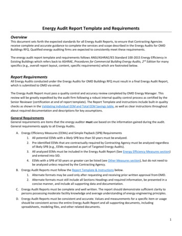
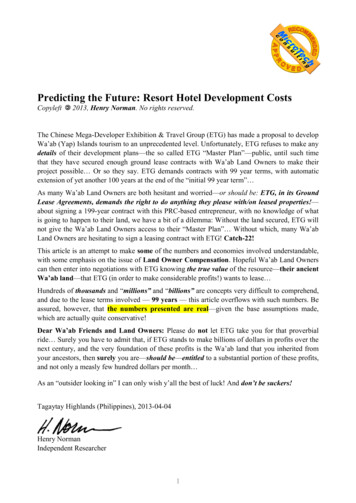
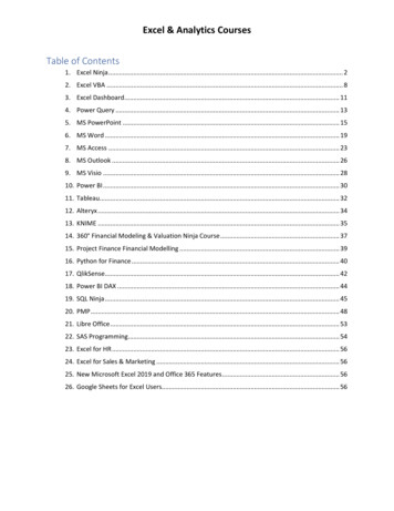
7.1.1.2.1 Fixed Roof TanksA typical vertical fixed roof tank is shown in Figure 7.1-1. This type of tank consists of acylindrical steel shell with a permanently affixed roof, which may vary in design from cone- or domeshaped to flat. Losses from fixed roof tanks are caused by changes in temperature, pressure, and liquidlevel.Fixed roof tanks are either freely vented or equipped with a pressure/vacuum vent. The latterallows the tanks to operate at a slight internal pressure or vacuum to prevent the release of vapors duringsmall changes in temperature, pressure, or liquid level. Fixed roof tanks may have additional vents orhatches, referred to as emergency vents, to provide increased vent flow capacity in the event of excessivepressure in the tank. Of current tank designs, the fixed roof tank is the least expensive to construct and isgenerally considered the minimum acceptable equipment for storing organic liquids.Horizontal fixed roof tanks are constructed for both above-ground and underground service andare usually constructed of steel, steel with a fiberglass overlay, or fiberglass-reinforced polyester.Horizontal tanks are generally small storage tanks with capacities of less than 40,000 gallons. Horizontaltanks are constructed such that the length of the tank is not greater than six times the diameter to ensurestructural integrity. Horizontal tanks are usually equipped with pressure-vacuum vents, gauge hatches andsample wells, and manholes to provide access.The potential emission sources for above-ground horizontal tanks are the same as those forvertical fixed roof tanks. Emissions from underground storage tanks are associated mainly with changesin the liquid level in the tank. Losses due to changes in temperature or barometric pressure are minimalfor underground tanks because the surrounding earth limits the diurnal temperature change, and changesin the barometric pressure result in only small losses. However, standing losses from undergroundgasoline tanks, which can experience relatively fast vapor growth after the ingestion of air and dilution ofthe headspace, are addressed in Section 5.2 of AP-42.7.1.1.2.2 External Floating Roof TanksA typical external floating roof tank (EFRT) consists of an open-top cylindrical steel shellequipped with a roof that floats on the surface of the stored liquid. The floating roof consists of a deck,deck fittings, and a rim seal system. Floating decks that are currently in use are constructed of weldedsteel plate and are most commonly of two general types: pontoon or double-deck. Pontoon-type anddouble-deck-type external floating roof tanks are shown in Figures 7.1-2 and 7.1-3, respectively. With alltypes of external floating roof tanks, the roof rises and falls with the liquid level in the tank. Externalfloating decks are equipped with a rim seal system, which is attached to the deck perimeter and contactsthe tank wall. The purpose of the floating roof and rim seal system is to reduce evaporative loss of thestored liquid. Some annular space remains between the seal system and the tank wall. The seal systemslides against the tank wall as the roof is raised and lowered. The floating deck is also equipped with deckfittings that penetrate the deck and serve operational functions. The external floating roof design is suchthat routine evaporative losses from the stored liquid are limited to losses from the rim seal system anddeck fittings (standing loss) and any liquid on the tank walls that is exposed by the lowering of the liquidlevel associated with the withdrawal of liquid (working loss). Because of the open-top configuration ofthis tank, wind effects have a significant impact on evaporative losses from this type of tank.06/2020Liquid Storage Tanks7.1-5
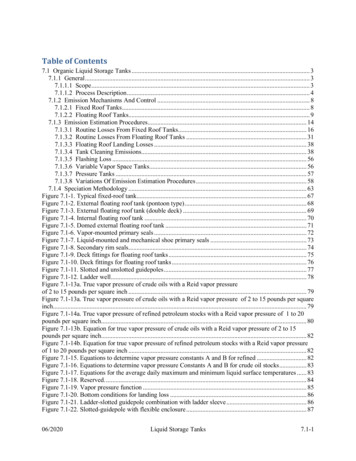
7.1.1.2.3 Internal Floating Roof TanksAn internal floating roof tank (IFRT) has both a permanent fixed roof and a floating roof inside.There are two basic types of internal floating roof tanks: tanks in which the fixed roof is supported byvertical columns within the tank, and tanks with a self-supporting fixed roof and no internal supportcolumns. Fixed roof tanks that have been retrofitted to use a floating roof are typically of the first type.External floating roof tanks that have been converted to internal floating roof tanks typically have a selfsupporting roof. Newly constructed internal floating roof tanks may be of either type. The deck in internalfloating roof tanks rises and falls with the liquid level and either floats directly on the liquid surface(contact deck) or rests on pontoons several inches above the liquid surface (noncontact deck). Themajority of aluminum internal floating roofs currently in service have noncontact decks. A typical internalfloating roof tank is shown in Figure 7.1-4.Contact decks include (1) aluminum sandwich panels that are bolted together, with a honeycombaluminum core floating in contact with the liquid; (2) pan steel decks floating in contact with the liquid,with or without pontoons; and (3) resin-coated, fiberglass reinforced polyester (FRP), buoyant panelsfloating in contact with the liquid. Variations on these designs are also available. The majority of internalcontact floating decks currently in service are aluminum sandwich panel-type or pan steel-type. The FRPdecks are less common. The panels of pan steel decks are usually welded together.Noncontact decks are the most common type currently in use. Typical noncontact decks areconstructed of an aluminum deck and an aluminum grid framework supported above the liquid surface bytubular aluminum pontoons or some other buoyant structure. The noncontact decks usually have bolteddeck seams.Installing a floating roof minimizes evaporative losses of the stored liquid. Both contact andnoncontact decks incorporate rim seals and deck fittings for the same purposes previously described forexternal floating roof tanks. Evaporative losses from floating roofs may come from deck fittings,nonwelded deck seams, and the annular space between the deck and tank wall. In addition, these tanks arefreely vented by circulation vents at the top of the fixed roof. The vents minimize the possibility oforganic vapor accumulation in the tank vapor space in concentrations approaching the flammable range.An internal floating roof tank not freely vented is considered an internal floating roof tank with a closedvent system. Emission estimation methods for such tanks are addressed in Section 7.1.3.8.2.7.1.1.2.4 Domed External Floating Roof TanksDomed external (or covered) floating roof tanks have the heavier type of deck used in externalfloating roof tanks as well as a fixed roof at the top of the shell like internal floating roof tanks. Domedexternal floating roof tanks usually result from retrofitting an external floating roof tank with a fixed roof.This type of tank is very similar to an internal floating roof tank with a welded deck and a self-supportingfixed roof. A typical domed external floating roof tank is shown in Figure 7.1-5.As with the internal floating roof tanks, the function of the fixed roof with respect to emissions isnot to act as a vapor barrier, but to block the wind. The estimations of rim seal losses and deck fittinglosses include a loss component that is dependent on wind speed and a loss component that is independentof wind speed. When a tank is equipped with a fixed roof, the wind-dependent component is zero due tothe blocking of the wind by the fixed roof, leaving only the wind-independent loss component.06/2020Liquid Storage Tanks7.1-6
The type of fixed roof most commonly used is a self-supporting aluminum dome roof, which is ofbolted construction. Like the internal floating roof tanks, these tanks are freely vented by circulation ventsat the top and around the perimeter of the fixed roof. The deck fittings and rim seals, however, areidentical to those on external floating roof tanks. In the event that the floating deck is replaced with thelighter IFRT-type deck, the tank would then be considered an internal floating roof tank.The distinction between a domed external floating roof tank and an internal floating roof tank isprimarily for purposes of recognizing differences in the deck fittings when estimating emissions. Inparticular, the domed external floating roof deck typically has significantly taller leg sleeves than aretypical of an internal floating roof deck. The longer leg sleeves of the domed external floating roof deckhave lower associated emissions than the shorter leg sleeves of the internal floating roof deck. While adomed external floating roof tank is distinct from an internal floating roof tank for purposes of estimatingemissions, the domed external floating roof tank would be deemed a type of internal floating roof tankunder air regulations that do not separately specify requirements for a domed external floating roof tank.7.1.1.2.5 Variable Vapor Space TanksVariable vapor space tanks are equipped with expandable vapor reservoirs to accommodate vaporvolume fluctuations attributable to temperature and barometric pressure changes. Although variable vaporspace tanks are sometimes used independently, they are normally connected to the vapor spaces of one ormore fixed roof tanks. The two most common types of variable vapor space tanks are lifter roof tanks andflexible diaphragm tanks.Lifter roof tanks have a telescoping roof that fits loosely around the outside of the main tank wall.The space between the roof and the wall is closed by either a wet seal, which is a trough filled with liquid,or a dry seal, which uses a flexible coated fabric.Flexible diaphragm tanks use flexible membranes to provide expandable volume. They may beeither separate gasholder units or integral units mounted atop fixed roof tanks. A variable vapor spacetank that utilizes a flexible diaphragm will emit standing losses to the extent that the flexible diaphragm ispermeable or there is leakage through the seam where the flexible diaphragm is attached to the tank wall.A variable vapor space tank will emit vapors during tank filling when vapor is displaced byliquid, if the tank's vapor storage capacity is exceeded.7.1.1.2.6 Pressure TanksTwo classes of pressure tanks are in general use: low pressure (2.5 to 15 psig) and high pressure(higher than 15 psig). Pressure tanks generally are used for storing organic liquids and gases with highvapor pressures and are found in many sizes and shapes, depending on the operating pressure of the tank.Low-pressure tanks are equipped with a pressure/vacuum vent that is set to prevent venting loss fromboiling and breathing loss from daily temperature or barometric pressure changes. High-pressure storagetanks can be operated so that virtually no evaporative or working losses occur. In low-pressure tanks,working losses can occur with atmospheric venting of the tank during filling operations. Vapor lossesfrom low-pressure tanks storing non-boiling liquids are estimated in the same manner as for fixed rooftanks, with the vent set pressure accounted for in both the standing and working loss equations.06/2020Liquid Storage Tanks7.1-7
7.1.2 Emission Mechanisms And Control2-8Emissions from the storage of organic liquids occur because of evaporative loss of the liquidduring its storage and as a result of changes in the liquid level. The emission mechanisms vary with tankdesign, as does the relative contribution of each type of emission mechanism. Emissions from fixed rooftanks are a result of evaporative losses during storage (known as breathing losses or standing losses) andevaporative losses during filling operations (known as working losses). External and internal floating rooftanks are emission sources because of evaporative losses that occur during standing storage andwithdrawal of liquid from the tank. Standing losses are a result of evaporative losses through rim seals,deck fittings, and/or deck seams. The loss mechanisms for routine emissions from fixed roof and externaland internal floating roof tanks are described in more detail in this section.7.1.2.1 Fixed Roof TanksThe two significant types of routine emissions from fixed roof tanks are standing and workinglosses. The standing loss mechanism for a fixed roof tank is known as breathing, which is the expulsionof vapor from a tank through vapor expansion and contraction that results from changes in temperatureand barometric pressure. This loss occurs without any liquid level change in the tank. The emissionsestimating methodology presented in Section 7.1 assumes the barometric pressure to be constant, andstanding losses from fixed roof tanks are attributed only to changes in temperature. As vapors expand inthe vapor space due to warming, the pressure of the vapor space increases and expels vapors from thetank through the vent(s) on the fixed roof. If the venting is of a type that is closed in the absence ofpressure, such as a weighted-pallet pressure-vacuum vent, then vapors are assumed to not be expelleduntil the pressure in the vapor space exceeds the set pressure of the vent.The evaporative loss from filling is called working loss. Emissions due to filling operations arethe result of an increase in the liquid level in the tank. As the liquid level increases, the pressure inside thevapor space increases a
06/2020 Liquid Storage Tanks 7.1-3 . 7.1 Organic Liquid Storage Tanks . 7.1.1 General 7.1.1.1 Scope Section 7.1 presents emissions estimating methodologies for storage tanks of various types and operating conditions. The methodologies are intended for storage tanks that