Transcription
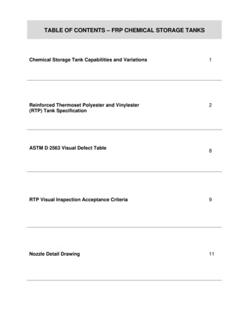
TABLE OF CONTENTS – FRP CHEMICAL STORAGE TANKSChemical Storage Tank Capabilities and Variations1Reinforced Thermoset Polyester and Vinylester(RTP) Tank Specification2ASTM D 2563 Visual Defect Table8RTP Visual Inspection Acceptance Criteria9Nozzle Detail Drawing11
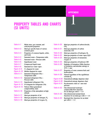
1 FRP Chemical Storage TanksChemical Storage Tank Capabilities and VariationsWith the 2003 acquisition of an existing FRP Tank manufacturing company, Spunstrand Inc. added significant large diameter filament winding capability, which enhances ourproduct offering significantly.Spunstrand Inc. now has a dedicated facility formanufacturing chemical and water storage tanks, carbon scrubbers and custom FRPproducts that will serve our primary industrial and municipal customers as well as emergingmarkets.FRP tanks have a wide variety of applications, and the below list is only a small example ofthe many applications that should be explored. Chemical storage (semi-conductor industry, wastewater treatment, water treatment,plating, oil fields, aerospace, food processing, leachate tanks, etc.) Water storage (fire water cisterns, potable water storage, chiller water storage, etc.) Chemical Vats (specialty plating operations)Our tanks are custom configured to our customer’s specific applications, including resin andliner recommendations, fitting locations and any other job-related needs. Available optionsinclude stiffening ribs for buried tank applications, insulated tanks, sloped bottoms, and anyother customer exacting requests to best suit their application.Our facility has a customized cantilevered 12’ diameter mandrel that allows us tomanufacture this specific size of tank with the tank bottom and sidewall integrally molded forthe highest level of corrosion resistance. While this option is limited to this one specificsize, it does offer a premium option for highly corrosive applications such as SodiumHypochlorite storage tanks.We also have special equipment that allows us to easilyproduct tanks with a BPO/DMA curing system for applications where traditional curesystems are not recommended.Spunstrand Inc. has many other options available to match our customer’s specific needs.Please contact us for further information on your FRP storage tank application.620 North Post Street Post Falls, ID 83854 208.777.7444 ph 208.777.7445 fax www.spunstrand.com
2 FRP Chemical Storage TanksSAMPLE SPECIFICATION FOR REINFORCED THERMOSETPOLYESTER AND VINYLESTER (RTP) TANKSProducts2.01 GeneralA. Reinforced thermoset polyester (RTP) tanks as manufactured by Spunstrand Inc , andshall be used to store liquid chemicals, waste water, or process solutions as shown onschedules and drawings.B. Tank Dimensions and �� -14’ Strt Shell Hgt20’ Liquid DepthTBDGallon CapacityTBDDesign Criteria:1.Seismic zone 3.2.Live loading:a.Internal pressure above liquid surface: Atmosphericb.Domed top, psf 100 psf3.Process:a.Liquid: Example - Sodium Hydroxide, 25%, specific gravity: 1.27, pH:14.4.Temperature, degrees F: 50 -105.5.A minimum structural safety factor of 5 shall be used in the design of the Vessel.6.Allowable strain for the tanks: 0.0010 in./in.7.Two lifting lugs per tank, minimum.2.03 MaterialsA. FRP Vessel1. Type: Filament wound rated at design pressures indicated in the drawings.Minimum wall thickness shall be .250. Wall thickness increases to be determined bydiameter and height. Chop hoop winding may only be bid as an alternate.2. Grade: Type 1, Grade 2 (VE) RTRP, Class V per ASTM D3299-88 and D2996.3. Vessel shall be designed for not less than the internal pressure and loads as indesign criteria.4. Tank top and bottom shall be fabricated and joined by contact molding.Spunstrand Inc. Specification-11/1/09-Version: 1.1
3 FRP Chemical Storage Tanks5. The resin used shall be Hetron 992SB selected to meet the exposures andtemperatures of chemical to be stored. Fillers other than antimony pentoxide addedfor flame retardance when required, shall not be allowed, and should not exceed 3%by weight. A thixotropic agent for viscosity control may be used as recommended bythe resin manufacturer. No thixotropic agent is to be used in the corrosion liner or onsurfaces to be in contact with the corrosive environment. Catalyst shall be DDM9 orHigh Point 90 as recommended by Ashland Chemicals.2.04Laminate Construction1. Tank Construction – The laminate comprising the structural tank (cylindrical shell, flatbottom, and domed heads) shall consist of a corrosion-resistant laminate comprisedof a corrosion liner, corrosion barrier and a structural layer.2. Corrosion Liner: Inner surface shall contain two (2) layers of a 10 mil thick minimumC-glass surfacing veil, saturated with vinylester resin. The surface veil shall beoverlapped a minimum of 1". Surface veil layers shall be followed by two (2) layersof 1-1/2 oz./sq. ft. chopped strand mat. Corrosion liner is to gel completely beforeproceeding with structural laminates. In no case shall the interruption exceed 24hours. Total minimum liner thickness to be 100 mils. No thixotropic agent or fireretardant additive is to be used in the liner resin. Corrosion liner shall contain not lessthan 20 % nor more than 30% glass by weight. The liner shall pass inspection forASME RTP-1 Table 6-1 visual acceptance criteria. BPO curing is an optiondepending on chemical exposure and concentration.3. Structural layer shall be filament wound of Hetron 992SB premium grade vinylesterresin with 3% Antimony Pentoxide and Type E 250 strand yield continuous glassroving. Filament winding cycle thickness to be 0.06" maximum. Glass content 55 to65 %. Winding angle shall be 70 to 80 . Chopped hoop winding and hand lay-upwill not be allowed in the structural layers. Minimum barcol hardness shall be 36 forall laminates.Exterior of all laminates shall contain a 10 mil A-veil and sufficient resin to insure arelatively smooth surface free from exposed glass fibers or sharp projections.Scrubber vessels located outdoors shall contain an exterior colored surface coat. Anultraviolet stabilizer added to the final coat of resin that also incorporates paraffinatedwax curing elements. Color to be selected by owner from Spunstrand Inc. colorchart.The manways shall be flanged and drilled per ANSI 16.5, 150 lb.Domed ends shall be factory attached and constructed to the same liner andstructural wall thickness. Chopper gun or hand-lay-up methods are acceptable solong as there is no antimony added to the 100 mil liner.Interior of the tank floor shall be flat, or sloped to allow complete drainage of thetank.Vessel shall be equipped with a 2” eccentric or siphon drain located as low aspossible on the tank wall.Spunstrand Inc. Specification-11/1/09-Version: 1.1
4 FRP Chemical Storage TanksEquip tank with a vertical clear strip extending from the top of the tank to the bottom.Form the clear strip by not coating a 6” wide strip with the pigmented exteriorcoating. The clear strip to have only the color of the resin used in the tankconstruction. If site glasses, or ultra sonic level are used, the clear strip iseliminated. Any site glasses shall be installed with ball valves top and bottom.2.05 Components and DesignA. Attachments and Materials1 Flanged nozzles conically gusseted to tank. Nozzles to withstand 1,500 lbs bending,2,000 ft/lbs torque. Flange diameter and drilling per ANSI B16,5, 150 lb.2. Equip the 1 1/2 inch dia. supply line with a siphon drain design that bends down at a45 angle to within 6 inches of the bottom of the tank.3. Shop assemble any tank accessories to ensure proper fit. Number subassembliesand matchmark mating flanges or elements to ensure correct alignment and correctfield assembly.4. Gaskets to be full faced 1/8” thick neoprene, EPDM, or viton depending on service.5. All metal fittings and wires exposed to the process liquid and anchor lugs shall beType 316L Stainless Steel.6. Metal fittings not exposed to the process fluids and all fasteners: ANSI Type 316Stainless Steel.2.06 Fittings and AccessoriesA. Tank # 001 (Typical)A.1 One (1) 3 inch Flanged Fill LineA.2 One (1) 6 inch Flanged VentA.3 One (1) 4 inch Flanged OutletA.4 One (1) 4 inch Flanged DrainA.5 One (1) 3 inch Flanged Level ElementA.6 One (1) 24 inch Manway w/Blind FlangeA.7 One (1) 3 inch Square w/Blind FlangeA.8 Two (2) Stainless Steel Lifting Lugs, Depending on DiameterA.9 Six (6) 304 Stainless Steel Anchor Lugs, Depending on Diameter2.07Testing1. Prepare QA Inspection Report addressing the following items:7.1.1 Visual Inspection per ASTM C582 D25637.1.2 Barcol hardness per ASTM D25837.1.3 Acetone sensitivity test for internal secondary bonds2. Hydrostatic Leak Test for both tanks (optional)7.2.1 Fill to top nozzle: Allow to stand for overnight with no visible leakage3. Identify and retain all cutouts from both tanks for inspection if requested.4. Factory shall certify the results by signature of the following:7.4.1 Inspections7.4.2 Hydrostatic testingSpunstrand Inc. Specification-11/1/09-Version: 1.1
5 FRP Chemical Storage Tanks2.08Marketing / NameplateSeal label into laminate exterior with clear resin with the following information:A. Fabricator’s NameB. Gallon CapacityC. Maximum TemperatureD. Design Pressure / VacuumE. Specific GravityF. PHG. ResinH. Minimum ThicknessI. Tank NumberJ. Tank NameK. Date Manufactured2.09 Shop Drawings / Calculations1. Calculation sheets for Tank #001 shall be included with the drawings and stamped bya Washington professional engineer.2. Attached drawings for Tank #001 shall be to scale with complete nozzle andattachment schedule.Spunstrand Inc. Specification-11/1/09-Version: 1.1
6 FRP Chemical Storage Tanks2.10 Quality ControlA.Reference Standards from Spec. Section 06510 for filament wound FRP Vessels andmaterials will apply for tank fabrication, materials, design, testing, and relatedaccessories.B.All FRP Vessels shall be fabricated and installed by qualified, experienced mechanics,who have a minimum of 3 years experience with the lay-up, fabrication and installation ofthis type of system.C.Factory Inspection:1.Owner shall be given access to the FRP Vessel and all quality control recordsduring fabrication and upon completion for the purpose of verifying compliance tothe Contract Documents.D.2.Inspection of tank, including examination of laminate cutouts and specimens, maybe performed by the Engineer. Notify the Engineer 72 hours in advance of theoccurrence of the following tank construction milestones:a.Extraction of the shell section, prior to beginning assembly work.b.Following complete assembly, prior to shipment.3.Manufacturer will label and retain all nozzle and manway cut-outs for a period ofone year.4.The owner shall maintain the right to tour the FRP duct manufacturer’s plantanytime that fabrication is in process prior to final shipment. The owner andengineer may exercise the option, without any advance notice, to tour the plant andinspect all stages of fabrication to ensure that quality control is being maintained.5.Inspection by owner does not relieve any responsibility of the fabricator to meet therequirements of this specification.6.Final Inspection - The engineer and owner may carry out a final inspection of theequipment prior to shipment. Fabricator shall give the owner a minimum of 5 days’advance notice of scheduled shipment. Prior to final inspection by owner, thevessel shall be cleaned of all foreign material, and shall be in a position that allowseasy access and viewing.7.Laminate visual acceptance criteria in compliance with spec. Section 06510.Acceptance:1.Lack of compliance with any aspect of the approved submittal specifications anddrawings will be grounds for rejection of the equipment.2.Repair of rejected equipment - Repair procedures must be approved by the ownerprior to implementation. No more than 5 percent of the surface area of each FRPvessel component may be repaired.Spunstrand Inc. Specification-11/1/09-Version: 1.1
7 FRP Chemical Storage Tanks2.11 SubmittalsA.Provide the following information in addition to the standard submittal requirements withthe Bid:1.The fabricator shall submit for approval all reference standards, calculations, fabricationdrawings, and all engineering details of the tank design prior to beginning fabrication.A.The submittal should include all information utilized by the fabricator whichdescribes specifically how their FRP vessels are manufactured. This should bein the form of shop drawings, standards, specifications, other shop instructionsand QC records. This should include, but not be limited to:1.)Resin Type2.)Types and amounts of filler.3.)Corrosion liner description4.)Reinforcement types for hand lay-up or chopped laminates.5.)For filament-wound laminates:a.)Helix angleb.)Glass content rangec.)Strand yieldd.)Strand by inch in the winding band.e.)Ply thicknessf.)Amount of chop or unidirectional roving interspersed withwinding, if any, and location within laminate.6.)For all fabricated parts.a.)Construction typeb.)Laminate thicknessc.)Ply sequencesd.)Glass content rangeB.Recommended procedure for the protection and handling of tanks prior toinstallation.C.Complete design calculations for tank signed by a structural engineer registeredin the State of Washington, verifying that the tank has been designed to meet alldesign criteria given in spec. section 13206, 06510 and seismic zone 3.1.Anchor bolting template for tank.2.Resin Manufactures verification of compatibility.3.Manufactures available gel coat colors.D.Complete O&M manuals to be delivered to contractor within 14 days of vessel delivery.Spunstrand Inc. Specification-11/1/09-Version: 1.1
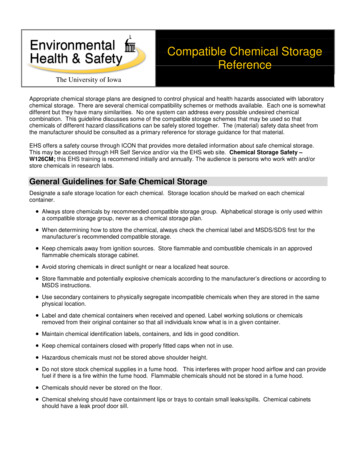
8 FRP Chemical Storage TanksASTM D 2563 VISUAL DEFECTSDefinition of Visual InspectionLevel: Level 2 StandardCorrosion ResistantMaximum Size and Cumulative Sum of Imperfections AllowableImperfections Subject to Cumulative Sum Limitation are Highlitedwith an AsteriskInterior LayerStructural( 0.125 in.Inner SurfaceLayer BalanceThick) Mat orVeil(s),of LaminateChoppedSurfacing(IncludingStrand SprayMatOuter Surface)LayersImperfectionNameDefinition ofImperfectionLevel 2Level 2Level 2NotesBurned AreasShowing evidence ofthermaldecompositionthrough discolorationor heavy distortionNoneNoneNoneDiscoloration only,never delaminationor decompositionChips (surface)Small pieces brokenoff an edge orsurfaceNone. . .*1/2 in. dia. or 1 in.length max. by1/16 in. deep. . .Dry Spot(surface)Area of surfacewhere thereinforcement hasnot been wetted withresinNone. . .None. . .Edge ExposureExposure of multiplelayers of thereinforcing matrix tothe vessel contents,usually as a result ofshaping or cutting asection to besecondary bonded(interior of vesselonly)None. . .NoneEdges exposed tocontents must becovered with samenumber of veils asinner surfaceForeignInclusionParticles included ina laminate which areforeign to itscomposition (not aminute speck of dust)*1/4 in. long maxby dia. orthickness notmore than 50%of veil(s)thickness*1/2 in. long max.by dia. or thicknessnot more than 50%of interior layerthickness*Nickel size, neverto penetratelamination tolaminationMust be fully resinwetted andencapsulatedGaseousBubbles orBlistersAir entrapmentwithin, on, orbetween plies ofreinforcement, 0.015in. diameter andlargerMax. dia. 1/16 in.by 50% of veil(s)thickness deepMax. dia. 1/8 in.Max. dia. 1/4 in.Must not bebreakable with asharp pointPorosity(surface)Presence ofnumerous visible tinypits (pinholes),approximatedimension 0.005 in.(for example: 5 inany sq in.)None more than50% of veil(s)thickness. . .Never to fullypenetrate theexterior gel coat orgel coated exteriorveil. No quantitylimitNo fibers may beexposedSpunstrand Inc. Specification-11/1/09-Version: 1.1
9 FRP Chemical Storage TanksRTP VISUAL INSPECTION ACCEPTANCE CRITERIADefinition of Visual InspectionLevels (to be specified by Useror User’s Agent): Level (1) Critically Corrosion Resistant,Level (2) Standard CorrosionResistantMaximum Size and Cumulative Sum of Imperfections Allowable[After Repair. See General Notes (a) and (b). Imperfections Subject toCumulative Sum Limitation are Highlighted with an Asterisk.]Inner Surface Veils(s),Surfacing MatInterior Layer (-0.125 inThick) Mat or ChoppedStrand Spray LayersStructural Layer Balanceof Laminate (IncludingOuter Surface)ImperfectionNameDefinition ofImperfectionLevel (1)Level (2)Level (1)Level (2)Level (1)Level (2)Scratches(surface)Shallow marks,grooves,furrows, orchannelscaused byimproperhandling*None*None.*Nonemore than6 in. long*Nonemore than12 in. longWet Blisters(surface)Roundedelevations ofthe surface,somewhatresembling ablister on thehuman skin;not reinforced*None over3/16 in. dia.by 1/16 in.in height*None over3/16 in. dia.by 1/16 in.in heightWet-outInadequateResin hasfailed tosaturatereinforcing(particularlywoven roving)NoneNoneWrinkles andCreasesGenerallylinear, abruptchanges insurface planecaused by lapsof reinforcinglayers,irregular moldshape, ormylar overlapMax.deviation20% of wallor 1/16 in.,whicheveris leastMax.deviation20% of wallor 1/8 in.,whicheveris least.Dry Spot(surface)Area of surfacewhere thereinforcementhas not beenwetted withresinNoneNone.EdgeExposureExposure ofmultiple layersof thereinforcingmatrix to thevesselcontents,usually as aresult ofshaping orcutting asection to besecondarybonded(interior ofvessel only)NoneNoneSpunstrand Inc. Specification.None.-11/1/09NotesNo fibers maybe exposed. . . . No Limit . . . Must be fullyresin filled; nodrips looselyglued tosurface,which are tobe removedNoneDry mat or prominent anddry woven roving patternnot acceptable;discernible but fullysaturated woven patternacceptableSplit tests oncutouts maybe used todiscerndegree ofsaturation onreinforcinglayersMax. deviation 20% ofwall or 1/8 in., whicheveris leastNot to causea cumulativelinear defect(outsidedefect addingto insidedefect)None.None-Version: 1.1None.NoneEdgesexposed tocontents mustbe coveredwith samenumber ofveils as innersurface
10 FRP Chemical Storage TanksRTP VISUAL INSPECTION ACCEPTANCE CRITERIA CONT’DDefinition of Visual InspectionLevels (to be specified by Useror User’s Agent): Level (1) Critically Corrosion Resistant,Level (2) Standard CorrosionResistantMaximum Size and Cumulative Sum of Imperfections Allowable[After Repair. See General Notes (a) and (b). Imperfections Subject toCumulative Sum Limitation are Highlighted with an Asterisk.]Inner Surface Veils(s),Surfacing MatInterior Layer (-0.125 inThick) Mat or ChoppedStrand Spray LayersStructural Layer Balanceof Laminate (IncludingOuter Surface)ImperfectionNameDefinition ofImperfectionLevel (1)Level (2)Level (1)Level (2)Level (1)Level (2)ForeignInclusionParticlesincluded inlaminate whichare foreign toits composition(not a minutespeck of dust)*3/16 in.long max.by dia. orthicknessnot morethan 30%of veil(s)thickness*1/4 in. longmax. bydia. orthicknessnot morethan 50%of veil(s)thickness*1/2 in.long max.by dia. orthicknessnot morethan 30%of veil(s)thickness*1/2 in.long max.by dia. orthicknessnot morethan 50%of veil(s)thickness*Dime sizenever topenetratelaminationtolamination*Nickel sizenever topenetratelaminationtolaminationGaseousBubbles orBlistersAir entrapmentwithin, on, orbetween pliesofreinforcement,0.015 in. dia.and largerMax. dia.1/16 in. by30% ofveil(s)thicknessdeepMax. dia.1/16 in. by50% ofveil(s)thicknessdeepMax. dia.1/3 in.Max. dia.1/8 in.Max. dia.3/16 in.Max. dia.1/4 in.NotesMust be fullyresin wettedandencapsulatedMust not bebreakablewith a sharppoint . . . Refer to User’s Specifications for Quantity Limitations . . . Must be fullyresin filledand wetted:generally,capturedsanding dustSmall, sharp,conicalelevations onthe surface ofa laminate*Max.height ordia. 1/64 in.*Max.height ordia. 1/32 in.Pit (surface)Small crater inthe surface ofa laminate*1/8 in. dia.max. by30% ofveil(s)thicknessmax.*1/8 in. dia.max. by50% ofveil(s)thicknessmax.*1/4 in. dia.max X 1/16in. deepmax.*1/4 in. dia.max X 3/32in. deepmax.No fibers maybe exposedPorosity(surface)Presence ofnumerousvisible tiny pits(pinholes),approx.dimension0.005 in. (forexample, 5 in.any sq. in.)None morethan 30%of veil(s)thicknessNone morethan 50%of veil(s)thickness.None to fully penetrate theexterior gel coat or gelcoated exterior veil. Noquantity limitNo fibers maybe exposedAllowableCumulativeSum ofHighlightedImperfectionsMaximumallowable inany sq. ft.Maximumallowable inany sq. yd.3 sq. ft.15 sq. yd.5 sq. ft.20 sq. yd3 sq. ft.20 sq. yd.5 sq. ft.30 sq. yd5 sq. ft.30 sq. yd5 sq. ft.40 sq. yd.Maximum %RepairsThe maximumallowable areaof repairsmade in orderto pass visualinspection10%3%structural,no limit tooutersurfacerepairs10%structural,no limit tooutersurfacerepairsDebond testsrequired priorto innersurfacerepairsPimples(surface)3%10%3% . . . No Limit . . . GENERAL NOTES:(a) Above acceptance criteria apply to condition of laminate after repair and hydrotest.(b) Noncatalyzed resin in not permissible to any extent in any area of the laminate.(c) Refer to Appendix M-9 for rules on repairs.Spunstrand Inc. Specification-11/1/09-Version: 1.1
11 FRP Chemical Storage TanksSpunstrand Inc. Specification-11/1/09-Version: 1.1
manufacturing chemical and water storage tanks, carbon scrubbers and custom FRP products that will serve our primary industrial and municipal customers as well as emerging markets. FRP tanks have a wide variety of applications, and the below list is only a small