Transcription
IWC 15-29Produced Water Treatment for Reuse in CyclicSteam Boilers and Crop IrrigationLyndsey WilesTriSep CorporationGoleta, CaliforniaLee PortilloEric NicholsOriginClearLos Angeles, CaliforniaPage 1 of 12
IWC 15-29KEYWORDS: California, Electrolysis, Irrigation, Membranes, Produced Water, Steam Generation, Oil& Gas, Produced Water, Ultrafiltration, Water Reuse.ABSTRACTAs water scarcity increases, reuse of the water generated by oil & gas exploration methods is becomingmore prevalent. This is especially true in California’s Central Valley, where the combination of oil &gas activity and historic drought conditions have pushed reuse to the forefront of many energycompanies’ efforts. With the main goal to treat produced water for beneficial reuse in their cyclic steamboilers and for agricultural irrigation, a Bakersfield, CA-based exploration and production company hasfound success with a treatment scheme featuring an electrolysis technology followed by a polymericultrafiltration (UF) membrane. Success of this treatment scheme was quantified via field testing inBakersfield throughout the early part of 2015. The electrolysis technology provided upfront de-oilingand bulk suspended solids removal, while the UF membrane removed any remaining oil and suspendedsolids to acceptable reuse levels. The raw feed had an average turbidity of 842 NTU and the treatmentscheme offered greater than 99.8% removal of turbidity. In addition, the oil levels being fed to theelectrocoagulation unit were in the range of 50-150 mg/l, while the UF membrane consistently providedeffluent with non-detectable levels of oil. The combination of solids and oil removal demonstrated to theoil producer that this treatment scheme provided effluent appropriate for their reuse purposes.Page 2 of 12
IWC 15-29INTRODUCTIONIndustry continues to face new challenges as water becomes increasingly scarce in many regionsacross the United States. One of the most discussed locations of water scarcity is California. Notonly is California currently facing one of its worst droughts in recorded history, but the state istrying to maintain its position as the top agricultural region in the U.S. In 2013 the total value ofagricultural cash receipts in California was 46.4 billion, making agriculture an extremelyimportant industry for the state (Tolomeo, 2013). Agriculture is also the largest consumer ofwater in the state, accounting for 80% of California's water use (Guo, 2015). In facing theongoing drought however, agriculture is struggling to not only operate as normal but to evenkeep fields alive as supply from the State Water Project and even Senior Water Rights literallydry up.Alternatively, another major industry in California, oil & gas, faces the opposite issue, namely anoverabundance of produced water that must be handled and managed. Throughout the history ofthe production of oil and gas, water has been a byproduct pumped out of underground formationsalong with the hydrocarbons. Oil & gas companies in California annually produce more than 2.5billion bbl of water from all onshore and offshore production activities (Clark and Veil, 2009).With ever-increasing water demands and historic drought conditions, oil producers and watertechnology companies are working together to turn California's produced water into a watersource.Produced water poses a unique and complex treatment problem that does not respond well totraditional treatment methods. Not only does it contain high concentrations of variouscontaminants such as boron and silica, but produced water also contains oil levels in the range of40-2,000 mg/l, total suspended solids (TSS) up to 1,000 mg/l, and total dissolved solids (TDS) inthe range of 1,000-400,000 mg/l (Clark and Veil, 2009). In order to treat this water to acceptablereuse levels, water industry experts are working together with producers to develop innovativetreatment techniques.TREATMENT TECHNOLOGIES: In order to treat produced water for reuse applications, suchas crop irrigation, a significant amount of contaminant reduction is required. Successfulproduced water treatment schemes will involve multiple sequential steps to combat the variety ofcontaminants present. Current technologies being tested and utilized for produced watertreatment include hydrocyclones, induced gas flotation, walnut shell filters, electrolysistechnologies, membrane filtration, ion exchange, chemical softening systems and more.Electrolysis technologies enter this landscape as a promising step in treating brackish oilfieldproduced water. Electrocoagulation (EC) is an efficient way to de-emulsify influent streams byproviding coagulating metal ions to a feed with high TSS and oil content. Electroflotation (EF)further enhances separation in gravity based separators by lowering the density of destabilizedmaterials, which decreases the residence time required for separation and thus system footprint.Electro-oxidation (EO) provides disinfection and can even demineralize certain contaminantsdown to carbon dioxide (Hurwitz, 2013). All three of these electrolysis technologies require aconductive medium to perform effectively, making the electrolyte-laden produced water aPage 3 of 12
IWC 15-29natural fit. The combination of these three electrolysis technologies provides the complete initialpretreatment required for the reuse of most produced waters.In order to further polish the water to reuse quality standards, another technology is sometimesrequired following the multi-stage electrolysis process. Ultrafiltration (UF) membranes offer aviable polishing step for produced water. Since UF operates via size exclusion, the large majorityof remaining non-dissolved contaminants will be removed. However, traditional polymericmembranes are easily fouled by oil, so a more oil-tolerant membrane is required. Thecombination of electrolysis technologies as an initial suspended oil and TSS removal step,followed by oil-tolerant UF membranes as a polishing step provides a promising treatmentscheme in treating produced water for reuse applications.This paper explores the use of electrolysis technologies followed by an oil-tolerant polymeric UFmembrane filtration for treatment of produced water at an oil production site in Bakersfield, CA.The oil producer's main treatment goals were to treat the water for the potential reuse in theircyclic steam generators or for crop irrigation.WATER QUALITY REQUIREMENTS: In order for the oil producer to reuse their producedwater, certain water quality requirements had to be met. Internally, their primary motivation forwater reuse was as feed to their cyclic steam generators. Prior to their cyclic steam generatorswas a chemical softening system for hardness removal. The main influent water qualityrequirements for their softening system were non-detect levels of oil and 5 ppm of TSS.Because the produced water at the site where this study was conducted had salinity levels of lessthan 1,500 mg/l, only hardness removal, and not complete desalination, was required beforebeing fed to the steam generators. The removal of these non-soluble parameters thus marked thefirst benchmark for reuse at this site.The second area of interest for water reuse for the oil producer in Bakersfield was to investigatethe feasibility of treating their produced water for crop irrigation. Water quality requirementsdiffer by crop, but there are some general guidelines to follow for irrigation, including salinitycontrol and toxicity control. In terms of produced water, significant oil reduction, TSS reduction,and TDS reduction are required. Table 1 below describes the general acceptable ranges for TDSand various ions in irrigation water. In order to meet acceptable salinity values for reuse asirrigation, an additional membrane desalination step was thus required and investigated for thisstudy.Page 4 of 12
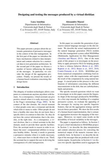
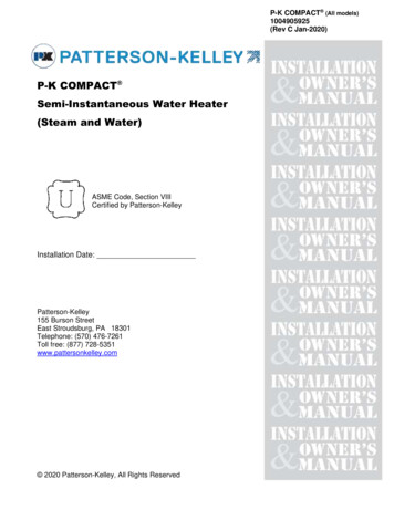
IWC 15-29Table 1: Acceptable salinity ranges for irrigation -10000-26.0-8.5(Martin, 1993)METHODS AND MATERIALSThe testing site was at a cyclic steam stimulation heavy oil production site on the east side ofBakersfield, CA. Testing was conducted between February to May 2015. During normaloperation at the facility, produced fluid containing low density oil, natural gas, and producedwater flows to an upfront three-phase separator, commonly referred to as a gun barrel separator.Following upfront oil-water separation at the gun barrel, the produced water passes through asequence of high residence time (up to 16 hours per tank) skim tanks before being deep-wellinjected for disposal.Feed water for testing was taken from the water leg of the upstream three-phase separator. Theinfluent was first fed to an upfront 25 micron suspended solids self-cleaning filter. Followingupfront coarse solids filtration, the electrolysis system was placed to break the influent emulsionand separate out the destabilized oil and suspended solids before being fed to the UF unit forfinal polishing. Figure 1 shows the process flow diagram for sequential treatment of producedwater during testing.Page 5 of 12
IWC 15-29Figure 1: Process flow diagram for testingThe electrolysis unit operated in this study was the Electro Water Separation, EWS , systemprovided by OriginClear. The system was comprised of three stages of electro-chemistry withinthe singular footprint: 1) electro-coagulation, 2) electro-floatation and 3) electro-oxidation.The electrolysis system was designed to remove up to 95% of non-soluble contaminants andprovide an initial dose of disinfection. The unit is controlled by a programmable logic controller(PLC), which operates the system at set treatment capacitates and maintains fluid levels withinthe separation chambers automatically. Floated destabilized material was collected in an oilsludge trough, which would automatically purge during operation. Settled solids removed in thesystem were collected in multiple solid collection points and purged periodically duringPage 6 of 12
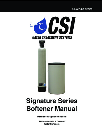
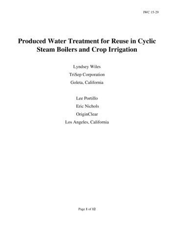
IWC 15-29operation. After pretreatment by the electrolysis system, the effluent was fed downstream for UFpolishing.The UF unit features an iSep 500-PVDF module, a permeate (vacuum) pump, permeate tank,backwash pump, chemical metering pumps, blower, automated valves, and otherinstrumentation. The UF module contains a proprietary 0.03 micron pore size polyvinylidenefluoride (PVDF) membrane that has significantly greater oil tolerance (up to 300 mg/l oil) thantraditional polymeric UF membranes. The module itself is a spiral-wound, submerged-style(vacuum-operated) module with air-scouring and backwashing capabilities. The UF unit containsa touch-screen HMI for control and automation, and all process sequences, including production,backwash, and chemically-enhanced backwash. The HMI also displays appropriate operatingconditions, such as feed flow, trans-membrane pressure (TMP), and temperature.During normal operation, the intermediary tank was purged to the downstream skim tankseparators and refilled every 20 minutes by the electrolysis unit. Water from the intermediatetank was then fed to the UF unit. The UF unit was programmed for automatic backwashes every15 minutes using permeate from its on-skid permeate tank. UF backwashes, permeate, and rejectall recirculated back to the intermediary tank.PERFORMANCE CHARACTERIZATION: For onsite characterization into the removal of nonsoluble contaminants, such as oil & grease and TSS, a Hach 2100Q was used to manually recordturbidity values. Periodically, sampling was performed and provided to third party analytical labsto analyze total recoverable petroleum hydrocarbons by the hexane extraction method (TRPHHEM), biological oxygen demand (BOD), chemical oxygen demand (COD), total suspendedsolids (TSS) and total petroleum hydrocarbons by GC/FID.For investigation in the feasibility of complete desalination, UF permeate was collected for usein laboratory cell tests utilizing two separate polyamide reverse osmosis (RO) membranes. Thistype of flat sheet testing is a critical tool to assess the treatability of certain waters and gives agood indication of a membrane’s removal capabilities for a specific application. The finaldesalinated permeate from the RO cell testing was tested for TDS, sodium adsorption ratio,boron, and TPH by GC/FID by an independent third party analytical lab.RESULTSMEMBRANE OPERATION: The UF unit was initially operated at a nominal module flux of 25gallons/ft2/day (gfd). Following successful initial operation, the flux was increased to a nominal30 gfd. Since the UF continued to receive high quality water from the electrolysis system, 30 gfdwas maintained for the remainder of testing. TMP and permeability remained fairly steadythroughout operation, as shown in Figure 2. This shows that the UF did not experienceprohibitive fouling, despite the presence of oil in the feed.Backwashes were performed using permeate stored in the on-skid UF permeate tank and wereconducted every 15 minutes for a period of 60 seconds. The backwash flow rate was set at a flowrate equal to two times that of the production flow. No chemical enhancements were employedduring backwash.Page 7 of 12
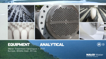
IWC 15-29Flux (gfd)35Permeability (gfd/psi)TMP (psi)302520151050050100150200Run Time (hours)250300350400Figure 2: Flux, permeability, and TMP of the UF throughout operationTSS / OIL REMOVAL: During testing, turbidity was used as a quantitative indicator of oil &grease and TSS removal, and was employed onsite in lieu of more time and equipment intensiveanalytical testing. Influent and UF pilot effluent turbidity values are summarized in Figure 3. Thedata shows consistent final water clarity over the complete operating time.The averageturbidity reduction for the entirety of operation was found to be 99.8%.Raw WaterAnalytical SamplingUF effluent1200Turbidity (NTU)100080060040
water flows to an upfront three-phase separator, commonly referred to as a gun barrel separator. Following upfront oil-water separation at the gun barrel, the produced water passes through a sequence of high residence time (up to 16 hours per tank) skim tanks before being deep-well injected for disposal. Feed water for testing was taken from the water leg of the upstream three-phase separator .