Transcription
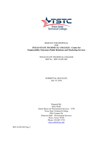
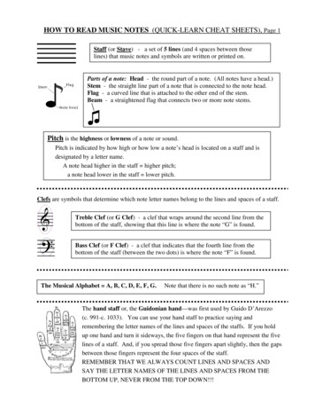
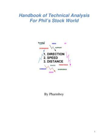
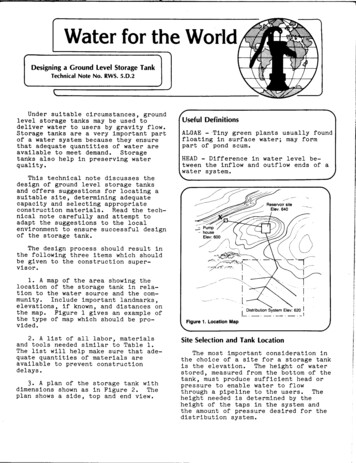
Designing a GroundTechnicalNotelevel Storage TankNo. RWS. 5.D.2Under suitablecircumstances,groundlevelstoragetanks may be used todeliverwater to users by gravityflow.Storagetanks are a very importantpartof a water system because they ensurethat adequatequantitiesof water areavailableto meet demand.Storagetanks also help in preservingwaterquality.FUseful DefinitionsALGAE - Tiny greenfloatingin surfacepart of pond scum.HEAD - Differencetween the inflowwater system.plantswater;usuallyfoundmay formin water levelbeand outflowends of aThis technicalnote discussesthedesign of ground levelstoragetanksand offerssuggestionsfor nd selectingappropriateconstructionmaterials.Read the technicalnote carefullyand attempttoadapt the suggestionsto the localenvironmentto ensure successfuldesignof the storagetank.The design processshould resultinthe followingthree items which shouldbe given to the constructionsupervisor.1. A map of the area showing thelocationof the storagetank in relation to the water source and the community.Includeimportantlandmarks,elevations,if known, and distancesonthe map. Figure1 gives an example ofthe type of map which should be provided.2. A listof all labor,materialsand tools needed similarto Table 1.The listwillhelp make sure that adequate quantitiesof materialsareavailableto preventconstructiondelays.3. A plan of the storagetank withdimensionsshown as in Figure2. Theplan shows a side,top and end view.Distribution System Elev: 620 1- -.-.i.-.-Flgure 1. Location MapSite Selection and Tank locationThe most Importantconsiderationinthe choice of a site for a storagetankThe heightof wateris the elevation.stored,measured from the bottom of thetank, must produce sufficienthead orpressureto enable water to flowThethrougha pipelineto the users.heightneeded is determinedby theheightof the taps in the system andthe amount of pressuredesiredfor thedistributionsystem.
r4fITable 1. Sample Materials pliesPortlandcementClean sand and gravelClean waterReinforcingrodPipe for inlets,overflowanddrain(PVC or steel)Screeningand wire mesh for pipesTarformsBoards and lumberLubricatingoilRocks,ifmasonryShovels,picks and othertoolsMeasuringtapePlumb lineHammerSawBucketsCarpenterssquareLevelblnor machineMixingPipe nkdlgglngTotal\fCoattankFloatvalve(if needed)Cut-offvalvesLock for manhole coverIron for steps In tankLumber and rafters,If woodenCover Str"Ct"PeShinglesPlywoodRope or stringNails,t1e wireToolsEstimatedEstimatedCost /Manhole and coverSide View--- - ----------L rE.cnI”1OverflowManhole andcoverWidth -- -End View--mm----\L-- ------Top View. .I--Figure 2. Storage Tank Design/2
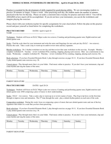
A generalrule to followis thatsmall water systems should have atleast14m of pressure.This means thatthe bottom of the storagetank must beat least14m higherthan the highestA generalrule is that the minitap.mum water levelin the storagetankshould be 20-4Om above the area served.Figure3 shows a profileof a system.Note that the elevationof the highesttap is 210m and that the system isbuiltfor a minimum of 14m pressure.The ground storageis on a hillat anelevationof 230m which providessufficientpressureto reach the highesttap in the community.If no locationof suitableheightis available,anelevatedstoragetank may be needed.For informationof the design of elevated storagetanks see "DesigninganElevatedStorage Tank," RWS.5.D.3.\ Figure 3. Distribution/In order to save money, try tolocatethe storagetank as close aspossibleto the water source and thepopulationbeing served.If possible,put it between the source and the populationto limitthe need for long linesof pipe.The locationof storageshown in Figure3 is distantfrom theofpump. This has the advantagedrawing water from the pump and tankdrum peak demand periods.For completeinformationabout the design of watertransmissionlines,the choice of pipe,and head losses due to friction,see"Designinga TransmissionMain,RWS.4.D.3 and System with Ground StorageTable 2. Population/’Growth Factors1. Determinethe populationof theUse census data or initiatecommunity.a survey to obtainpopulationfigures.Check past recordsto determinetherate of populationgrowth over theyears.If funds permit,the storagetank should be designedto last fortwenty-fiveyears.Therefore,use theestimatedpopulationfor 25 years inthe futureto determinedemand forwater.Use the growth factorsin Table2 when estimatingfuturepopulation.If money is short,the storagetank canbe sized to serve only the currentpopulationand the size Increasedlateron, if necessary.Tank CapacityThe capacityof the storagetank isimportantfor the efficientoperationof a water supply system.The tankshould be large enough to store sufficientwater to meet both average andpeak dailydemands.When designingastoragetank keep in mind that demandfor water variesduringthe year.Inthe hottermonths, people use morewater than in coolermonths and on certain religiousor culturaloccasionswater use may increase.For example,the presentpopulationof a community Is approximately1300and it has been growingat a rate of 3percentper year.To determinethepopulationin 25 years multiply1300 bythe populationgrowth factor1.81 foundin the row marked 20 and the 3 percentcolumn in Table 2.The firststep in determiningstoragecapacityis calculatingthedemand for water in the community.Follow the steps below in estimatingdemand.Population 1300 x 1.81Population 2350 or approximately2400.The reservoirshould be designedpopulationof 2400 people.3fora
/2. Once the populationis known, thedemand for water can be calculated.Demand can be estimatedby consideringthe type of distributionsystem used.Table 3 shows estimatedwater consumption rates for differenttypes ffectingdemand isthe use of water for purposesotherthan householddrinkingand cleaning.If the community has hotelsandrestaurantsor if animals willbewatered from the publicsystem consumption figureswould reflectthese uses.Table 4 shows estimatedwater use forvariousinstitutionsand for animals.Use these figureswhen designingthecapacityof the reservoir.Table 3. Estimated Water ConsumptionType of WaterAt distanceAt distanceVillagePeak day 1.2liters/dayAveragewater (250m)(250m)Yard connections1ng1e tapornouse 0;;I:;12IO-151510-204020-607050-120(or more)\//\Table 4. Water Use rpersonBus Horsesliters/dayx 120000wellStandpipe3. Once the totaldailydemand isdetermined,peak demand should be considered.Peak demand is the highestrate of demand duringthe day.Usuallypeak demand occurs duringthe morningwhen people get up to begin the day andin the earlyevening afterwork iscompleted.Peak demand is estimatedbyadding 20-40 percentto average dailydemand.Multiplythe average dailydemand by 1.2 or 1.4.For example,day 120000SupplyCommunity water point(i.e.,well, spring,public standpipe)The totaldailydemand for water canbe calculatedusing WorksheetA. Thecalculationsare done for a populationof 2400 people in a town that has asmall hospitalwith twenty beds, onehotelfor 75 people and two schools.Alarge chickenfarm with 5000 chickensalso uses water from the publicsystem.It is estimatedthat 40 percentof thepopulationwillbe served by multipletaps,35 percentby singletaps in theyard and 20 percentby standpipe.Fivepercentwillhave no service.AverageLand MulesPoultry*Chickens 1440000.15-0.25*Ifat allpossible,usepublicsupplyfor livestockshouldbe avoided.A generalrule to followis that thecapacityof the storagetank should be20-40 percentof the peak day waterdemand.With a peak dailydemand of144000 liters,the capacityof the tankshould be at least30m3: 144000 litersx.2 30000 liters.At the 40 percentvalue,the tank would be 58m3: 144000litersx .4 58000 liters.In thisof between 40case, a reservoir\ofperheadwaterfromand poultrya/50m3 would be needed to meet peakA possibledesign size woulddemand.For this capacitybe 5.5m x 4m x 2.3m.the water heightin the tanktank,should be at least2m and some spaceshould be availablebetween the highwater leveland top of the tank.4
The storagetanks can be builteitherabove or partiallyor completelybelow ground.Undergroundstructuresprovideadded supportfor the walls.If soilconditionspermitand elevationis sufficient,a storagetank partiallyor totallyundergroundis recommended.Where such a tank cannot be Installed,at leastbuildthe form work In theground for support.If a steeltank ispurchased,the tank willbe placeddirectlyon a concreteslab on the surface of the ground.Steel tanks provide good storagebut may not befeasib-lein many places due to theircost.Tank DesignGround levelstoragetanks aregenerallymade from reinforcedconcrete,masonry or brickdependingonthe materialsavailableIn the area andthe skillsof the localpeople.Steeltanks may be purchased.Reinforcedconcreteis used in manyareas.Its advantagesare that it provides a very sturdywatertightstructure that willlast many years,and ituses less concretethan mass concretestructureswhich reduces constructioncosts.A disadvantageof using a reinforcedstructureis that steel,lumberfor forms and skilledlabor and supervisionare needed to buildthe tank.Neitherthe materialsnor the expertisemay be affordableor available;if not,an alternativestructuredesign shouldbe chosen.All tanks must have covers.In somecases,reinforcedconcreteis used butforms are expensiveand constructiondifficult.Cast-in-placeroofingmaynot be possible.A concretecover canbe builtby castingseveralsections;;z fY&ingthem togetheron the top ofSee Figure5. The advantageof castingin sectionsis that thesmallersectionscan be cast at groundleveland liftedinto place.If large buildingstone isavailable,the tank can be builtofmasonry.When buildingwith masonry,no forms are necessaryand constructionis generallyeasier.Masonry tanks arenot watertight,however.For bestresults,make thin masonry wallsandfillIn between them with concreteasshown in Figure4./CROSS-SECTION/Cover sectionsSupporting wall for- coverof large tankCover\END VIEW/coversectionConcrete mortar on1oncrete foundation and floorForms full 01concrete, troweledsmooth‘Form half fullof concrete,reinforcingbars in placeWooden formsFigure 4. Example of Mass Concrete Wall ConstructionFigure 5. Casting Cover Sections5
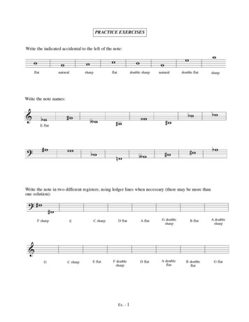
A wooden roof structurecan be madewith shingles,slate,or roofingtarplaced on it to make it watertight.Roofingstructuresfollowthe generaldesign patternfor house roofs andshould extend well beyond the ends ofthe tank so that rain runs away fromthe structure.All ground levelstorageshould be designedwith thefeatures.See Figure6./Overflow and vent :ManholetanksfollowingManholes and TightlyFittingManholeManholes with raisedcoversCovers.Theyshould be installedin each tank.preventthe entranceof dust, debrisand sunlightwhich is a major factorinthe growth of algae.The manholesshould have a diameterof 0.8-lm,sufficientto allow a person access to thetank for cleaning.A screenedventilationVentilation.pipe should be installedto allow airto escape from the tank when waterenters.The pipe should be screenedsobats or debriscanthat no insects,enter the storagetank.Inlet,Outlet,Overflowand Drain.The inletpine should be locatednearthe bottom-ofthe tank.In many cases,the same pipe acts as both intakeandoutlet.The end of the pipe should bescreenedand should be at least150mmabove the floorof the tank.Below theintake-outletpipe, water is not ableInstead,thisto leave the reservoir.area acts as a settlingzone for parPVC, or steelpipeticles.Plastic,The choicecan be used for the outlet.depends on availabilityand cost.The overflowpipe should be locatedabove the expectedhigh water levelinthe tank.The overflowpipe should bescreened.Water that overflowsfromthe tank should be moved away from itto preventcontaminationand the accumulationof standingwater in whichLay rock aroundmosquitoescan breed.the tank or line a small diversionditchto move all water away from theThe overflowpipe can also servearea.as an air vent.\Figure 6. Ground Level Storage TankA drain pipe should be installedatTo ensure adethe bottom of the tank.quate drainage,slope the floortowardInstalla drainpipe with athe drain.diameterlarge enough, perhaps 200mm,so that sedimentcan be flushedwithoutcloggingthe pipe.To controlOther Design Features.the levelof water in the tank,theinstallationof a floatvalve is recommended.If a floatvalve is not used,the operatormust be well trainedtoensure that water is pumped to storagewhen needed and not wasted throughtheoverflow.Small tanks can eitherbe builtas a6 orsingleunit as shown in Figuredividedinto two sectionsas shown inthe twoFigure7. A wall dividesstoragecompartmentsand pipes andvalves are arrangedso that each can beThis arrangementused separately.allowsfor continuousservicewhen oneOne alternativeside is being cleaned.is to builda singlestoragetank as inFigure6 and make a wall strong enoughto act as a partitionif expansionisAnothercomdesiredin the future.partmentcan be added when and if it isneeded, and the cost can be postponedto a laterdate.
Where suitableconditionsexist.ground levelstoragetanks are a goodchoice.They requirea great dealof materialfor construction.WorksheetB shows the generalcalculationsfor a one compartmentstoragetank made of reinforcedconcrete.Using these calculations,determinethespecificamounts needed and cost of allmaterials./IIIWorksheet A. CalculatingPopulation1.2400taps in homes of 40% of population40% x 2400 x 70 lpcdMultiple2. Single4.Two schools5.Chickensfor3360020% of population20% x 2400x 15 lpcd500with1000 x 20students72002000lpcd(5000)50006. HospitalwithHotel75 guests7.67200tap in yards or 35% of population35% x 2400 x 40 lpcd3. StandpipeThe concretemixtureshould be 1part cement to 2 partssand to 3 partsgravel(1:2:3)and 1Omm reinforcingbars laid in a grid patternshould beAll barsused for the wallsand cover.should be separatedby 150mm.Water Demandx 0.21000lpcd20 beds without20 x 160 lpcdlaundry3200562575 x 75 lwdI’Total119825For all storagefacilities,experiencedbuildersare needed to dothe work properlywhether masonry tanksor reinforcedtanks are built,constructionexpertiseis essential.Never attemptconstructionwithouttheexpertadvice of an engineerorbuilder.‘iii;;:!,compantenrSeparating wall“.’ 9Valves forcompartment #2.,.’InletDrain valvesCROSS-SECTION’tletTOP VIEWFigure 7. Storage Tank wlth Two Compartments7
rP/Worksheet B. Calculation of Quantity of Materials Needed for aReinforced Concrete Reservolr(5Sm x 4m x 2.3 with Cover of Concrete Sections)TotalVolumeThicknessof Reservoirofwalls length1. Volumeoftopcover12. Volumeoftwofrontside3. Volumeoftwo4. Volumeofbottom5. Totalvolume6. Unmixedofwalls each1,materialSand:.33Gravel:.5 x totalLf.02,3,volumeofofcement10.Volumeof water11.NumberofLengthiSides 2 endsvolumesand,.Z'l?rm3-Notes: 320bars150mm height5.5 .15s.7 g.8m3.15x 1.5l/6,l/3, cm31/2j2 Lm3sandgravelbagsbagsatorm3 cement 3920liters150mm apartofbars15 x 2 36.67 &8.t /&Y-m31:2:3 /yof 150mm number3 .15xvolume of cementper bag (.033mj/bag)x mplaced 25.15 2.3:gtx 1.5 Em30.033m3 a .m3x 2 zm3xgravel - 4.L i 7.2. /3.m3 28 liters/bagreinforcingTop and BottomJ&&x2 Total &m3xz .nJ4, am3Em3cementx0.z. &'.7JTsrn3volumexA.3 totalvolumex total50k bagsx(cement,x total8.2. m X/m3x d. 3volume9. Volumex heightx4.2.foundationof materialscement:ofx --s.rincluding.1678. Number 5.7walls sum ofvolume7. Volumex width 0.2mx 2 2L.67 .15needed3/5.33 15.33x 2 jBx 2 5tx2 &x 2 4% 18x2 *x 2 barsl overoverhangs2To save cement,3Rods are placedthe edge; tipsforcingrods InoutsideedgeO.lm on each sideuse a mixtureof 1:2:4so that lastrod parrallelto the edge Is .75mm fromof rods are 25mm from the end of walls;placerelnforms so that they are one-thirdthe distancefrom thr3/Notea are part of a set of “Water for the World” materials produced under contract to the U.S. Agency for International Development by NationalDemonstration Water Project, Institute for Rural Water, and National Environmental Health Association. Artwork was done by Redwing Art Service. Technical Notes areintended to provide assistance to a broad range of people with field responsibility for village water supply and sanitation projects in the developing nations. For moredetail on the purpose, organization and suggestions for use of Technical Notes, see the introductory Note in the series, titled “Using ‘Water for the World TechnicalNotes.” Other pads of the “Water for the World” series include a comprehensive Program Manual and several Policy Perspectives. Further information on thesematerials may be obtained from the Development Information Center, Agency for International Development, Washington, DC., 20523, U.S.A.Tochnlcal/L84
Storage tanks are a very important part of a water system because they ensure that adequate quantities of water are available to meet demand. Storage tanks also help in preserving water quality. This technical note discusses the design of ground level sto