Transcription
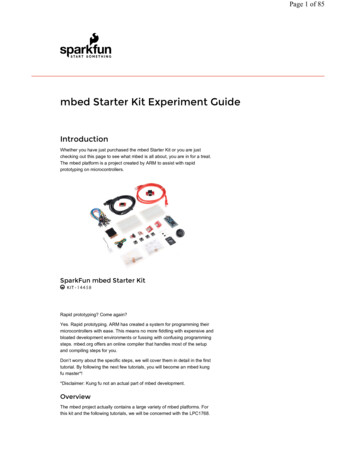
Page 1 of 85 mbed Starter Kit Experiment GuideIntroductionWhether you have just purchased the mbed Starter Kit or you are justchecking out this page to see what mbed is all about, you are in for a treat.The mbed platform is a project created by ARM to assist with rapidprototyping on microcontrollers.SparkFun mbed Starter Kit KIT-1445 8Rapid prototyping? Come again?Yes. Rapid prototyping. ARM has created a system for programming theirmicrocontrollers with ease. This means no more fiddling with expensive andbloated development environments or fussing with confusing programmingsteps. mbed.org offers an online compiler that handles most of the setupand compiling steps for you.Don’t worry about the specific steps, we will cover them in detail in the firsttutorial. By following the next few tutorials, you will become an mbed kungfu master*!*Disclaimer: Kung fu not an actual part of mbed development.OverviewThe mbed project actually contains a large variety of mbed platforms. Forthis kit and the following tutorials, we will be concerned with the LPC1768.
Page 2 of 85If you have purchased the mbed Starter Kit or the LPC1768, open up theLPC1768 box, and you will find a pinout card. This card is extremely usefulfor finding out which pins do what on the LPC1768.FeaturesHere are the technical specifications of the LPC1768: NXP LPC1768 MCU ARM Cortex -M3 Core 96MHz 32KB RAM 512KB FLASH Ethernet, USB Host orDevice, SPI x2, I2C x2, UART x3, CAN,PWM x6, ADC x6, GPIO Platform form factor 54x26mm 40-pin 0.1" pitch DIP package 5V USB or 4.5-9V supply Built-in USB drag ‘n’ drop FLASH programmerSuggested Reading What Is Electricity?Voltage, Current, Resistance, and Ohm’s LawWhat is a Circuit?How to Use a BreadboardAnalog vs. DigitalBinaryLogic LevelsDigital LogicPulse-width ModulationPull-up ResistorsLightTable of Contents
Page 3 of 85Now for the part you have been waiting for. The tutorials! This is where youget to open your mbed kit and play with all those cool parts. You shouldstart with Tutorial #1 in order to get familiar with mbed.org and theprogramming environment.Tutorial 1 - Getting StartedWe setup the mbed.org development environmentand create our first program: Blinky!Tutorial 2 - Buttons and PWMLet’s make some light! We use some buttons tocontrol the colors of an RGB LEDTutorial 3 - Graphic LCDThe mbed kit includes a 1.44" LCD that we canmake do cool things. We learn how to draw textand shapes on the LCD.Tutorial 4 - AccelerometerNow we start to pick things up. Literally. Using theaccelerometer, we can interact with the mbed bytilting it in different directions.Tutorial 5 - Internet ClockThe LPC1768 has the ability to connect to theInternet. Using an Ethernet cable, we can read thecurrent time from an Internet server and display thetime on our LCD.Tutorial 6 - USB Host and ThreadingOur mbed board can act like a USB host. Thismeans that we can connect things like keyboardsto it.Tutorial 7 - USB DeviceIn addition to acting like a USB host, the mbed canalso act like a USB device! This means that we canhave it control the mouse pointer on our computer,for example.Tutorial 8 - Temperature LoggingWant to see how the temperature varies over timein an area? We connect a temperature sensor andan SD card to the mbed to log temperaturemeasurements.Tutorial 9 - PWM SoundsLet’s make some music! We can use pulse-widthmodulation (PWM) to control sounds out of aspeaker or set of headphones.Tutorial 10 - Hardware SoundboardIn the final project, we load some sound clips ontoour SD card and use the mbed to play onewhenever we push a button.
Page 4 of 85Experiment 1: Blink an LEDWelcome to the world of mbed! In the following series of tutorials, we willshow you how to configure your mbed.org account, connect somehardware, and program your mbed controller to do some cool things. Eachtutorial will list the required components, but if you are just starting out withmbed, we recommend you get the mbed Starter Kit, which will provide allthe necessary hardware to complete the tutorials.In this tutorial, we will unbox the mbed LPC1768, connect it to ourcomputer, configure our mbed.org profile, and write our first blinking LEDprogram.Account SetupFor this first tutorial, we will be using the LPC1768 and the USB mini-Bcable. So, open your mbed NXP LPC1768 box and remove the LPC1768controller and USB cable.Plug one end of the USB cable into the LPC1768 and the other end intoyour computer. The blue power LED should light up.After a few seconds, your computer should recognize the mbed controlleras a standard USB drive. Open up a Windows Explorer (Windows) orFinder (OS X) and navigate to the mbed drive.
Page 5 of 85Double-click on the MBED.HTM link, which should open up a webpage thatasks you to create a new mbed account.IMPORTANT: Some older versions of the LPC1768 contain a link to apage that does not exist. If you get an error, navigate to mbed'sAccount Signup page to create an account.Click “Signup” and follow the prompts to create a new mbed.org account.Once you have created an account, navigate to developer.mbed.org.Click on “Login or signup” if you are not already signed in. Once signed in,click on “Compiler” in the top right. You will be presented with mbed’s onlinecompiler.The CodeIn the upper-left corner of the mbed Compiler, select “New” and then “NewProgram.”
Page 6 of 85You will see a prompt appear asking you to name your new program. Makesure that “Blinky LED Hello World” is selected for your Template and that“mbed blinky” is set as your Program Name.Click “OK” and you will see your new program appear in your workspace.Click on “main.cpp” in the pane on the left side to open up our C program.The code imports the mbed.h library, configures the pin for the LPC1768’sonboard LED to output, and blinks the LED forever. It has been copied herefor reference.#include "mbed.h"DigitalOut myled(LED1);int main() {while(1) {myled 1;wait(0.2);myled 0;wait(0.2);}}On the top bar, click “Compile.”
Page 7 of 85This will start the compile process and download the program as a binaryfile. Depending on your browser settings, this might be automaticallydownloaded. If you are asked where to download the file, choose yourdefault Downloads folder.Open up an Explorer (or Finder on OS X) window and navigate to yourDownloads folder. You will see your blinky program as a .bin file.Copy the .bin file to your MBED drive.If you look in the MBED drive, you should see two files: the originalMBED.HTM link and your new blinky program.Without disconnecting the USB cable, press the button in the middle of theLPC1768. You should see the bottom left LED begin to flash off and on.The blinking LED shows that your code is running!
Page 8 of 85ConceptsThis is our first program with the mbed, so we should talk about what isgoing on.Setup and LoopIf you have used Arduino in the past, it might come as a surprise that youwere writing code in a language very close to C and C . One thing youshould be aware of is that Arduino wraps up the setup and loop stages intonice functions for you. For example, you might see this in Arduino:void setup() {// Your setup code goes here}void loop() {// Your loop code goes here}In Arduino, the setup code runs once, and the loop code runs forever.In mbed (and most other embedded systems), we must create our ownsetup and loop sections within main(). Every C and C program musthave a main() function, as this is the entry point for the program (i.e. this iswhere the program begins execution when you run it).Using our concepts of setup and loop, this is what the basic template lookslike in mbed:int main() {// Your setup code goes herewhile(1) {// Your loop code goes here}}Much like in the Arduino example, the program executes the setup codeonce (as soon as it enters the main() function) and executes the loop codeforever. Notice that we explicitly put the loop code inside of a while loop. Itis possible to make the while loop exit, and the program would stoprunning. You would need to reset the microcontroller to restart the program.Header FilesThe very first line in our blinky program is
Page 9 of 85#include "mbed.h"This tells the compiler to include (i.e. copy into our program) a separate file(mbed.h in this case) when we compile. mbed.h is a header file thatdeclares a set of functions, constants, classes, etc. for our use. Many times,the implementation of these functions, constants, classes, etc. are definedin a separate library, and the header file provides an interface. As long aswe include the header file and the header file and library are in our searchpath (for our mbed programs, just make sure that the library is copied intoour project directory - shown by the little gear icon in this example), we canuse the functions, constants, classes, etc. listed in the header file.Going FurtherThis is just the beginning! You got a taste of the mbed Compiler and builtyour first program. Now that you understand how to use the mbedCompiler, we will move on to more advanced topics and show you how toconnect other pieces of hardware to make the LPC1768 do fun andinteresting things.Beyond the Tutorial Can you make the LED blink slower? Can you make another LED blink? Can you make an LED blink exactly 10 times and then stop? (Hint:the while(1) loop continues forever. How would you modify that tostop after 10 times?)Digging Deeper Read about mbed’s SDKRead about mbed’s HDKRead about mbed’s CompilerRead about mbed’s websiteTake a look at mbed’s Handbook, which has official mbed librariesTake a look at mbed’s Cookbook, which has user-submitted librariesand projectsExperiment 2: Buttons and PWMNow that you have had a chance to set up your mbed account and blink anLED, we will move on to simple human interaction: pushbuttons! In thistutorial, we add 3 pushbuttons to the LPC1768 and use them to control thecolors in an RGB LED.
Page 10 of 85The CircuitThis circuit can be made with parts in the SparkFun mbed Starter Kit. Also,keep in mind that the LPC1768 box contains a USB mini-B cable forprogramming and power.Parts ListTo follow this experiment, you would will need the following materials if youdid not order the SparkFun mbed starter kit. You may not need everythingthough depending on what you have. Add it to your cart, read through theguide, and adjust the cart as necessary. The experiment will be using 3x330Ohm and 3x 10kOhm resistors.mbed Starter Kit - Part 2: Buttons and PWM SparkFun Wish ListResistor 10K Ohm 1/4 Watt PTH - 20 pack (Thick Leads)PRT-14491Resistor 330 Ohm 1/4 Watt PTH - 20 pack (Thick Leads)PRT-14490mbed - LPC1768 (Cortex-M3)DEV-09564The mbed microcontroller is an ARM processor, a comprehensive set (3) Momentary Pushbutton Switch - 12mm SquareCOM-09190This is a standard 12mm square momentary button. What we really li LED - RGB Clear Common CathodeCOM-00105Ever hear of a thing called RGB? Red, Green, Blue? How about an R Jumper Wires Standard 7" M/M - 30 AWG (30 Pack)PRT-11026If you need to knock up a quick prototype there's nothing like having a (2) Breadboard - Self-Adhesive (White)PRT-12002This is your tried and true white solderless breadboard. It has 2 power SchematicClick on schematic to view larger image.
Page 11 of 85ConnectionsConnect the LPC1768 to the buttons and LED in the following fashion.PolarizedComponents Pay special attention to the component’s markingsindicating how to place it on the breadboard. Polarizedcomponents can only be connected to a circuit in onedirection. Polarized components are highlighted with ayellow warning triangle in the table below.Fritzing DiagramBe careful with the direction of the LED (polarity matters!). In the diagram,the flat edge (see the Tips section below) is facing to the left.Note that the colors of the wires do not matter. Feel free to use any coloryou like! Do not worry if your kit does not have 5 black wires.Hookup TablePlace the LPC1768 in the first breadboard with pin VOUT in position i1 andpin 20 in position b20.Connect the rest of the components as follows:ComponentRGB LEDBreadboard 7330Resistore28g28 b27(GREEN)Breadboard Pushbuttond22d24g22g2410kResistori6( )
Page 12 of 8510kResistori14( )10kResistori22( )JumperWirej1( 16(-)JumperWirea24(-)TipsPushbuttonsThe leads across each other on the pushbuttons are always connected toeach other. The leads on the same side are only connected when button ispressed.
Page 13 of 85LEDYou can use a set of needle nose pliers to bend the LED’s leads and a pairof cutters to fit the LED in the breadboard. Note that there is a flat side onthe plastic ring around the bottom of the LED. This denotes the side withthe pin that controls the red color. See this tutorial to learn more aboutpolarity.Resistors330 ohm resistors are given by the color code “orange orange brown.”330 ohm resistors10k ohm resistors are given by the color code “brown black orange.”
Page 14 of 8510k ohm resistorsThe CodeIf you have not done so already, sign into your mbed.org account. Go to theCompiler and create a new program. Leave the template as “Blinky LEDHello World” and give it a name such as “rgb buttons.” Click OK and waitfor your new program to be created.Once that is done, click “main.cpp” under your project folder (e.g.“rgb buttons”) in the left “Program Workspace” pane. Delete all of the codein main.cpp so you are left with a blank project (we still want to use the“Blinky LED Hello World” template, as it automatically links “mbed.h” forus).ProgramCopy the following code into main.cpp of your rgb buttons project.
Page 15 of 85#include "mbed.h"// Define buttonsInterruptIn button red(p5);InterruptIn button green(p6);InterruptIn button blue(p7);// Define LED colorsPwmOut led red(p21);PwmOut led green(p22);PwmOut led blue(p23);// Interrupt Service Routine to increment the red colorvoid inc red() {float pwm;// Read in current PWM value and increment itpwm led red.read();pwm 0.1f;if (pwm 1.0f) {pwm 0.0f;}led red.write(pwm);}// Interrupt Service Routine to increment the green colorvoid inc green() {float pwm;// Read in current PWM value and increment itpwm led green.read();pwm 0.1f;if (pwm 1.0f) {pwm 0.0f;}led green.write(pwm);}// Interrupt Service Routine to increment the blue colorvoid inc blue() {float pwm;// Read in current PWM value and increment itpwm led blue.read();pwm 0.1f;if (pwm 1.0f) {pwm 0.0f;}led blue.write(pwm);}// Main loopint main() {// Initialize all LED colors as offled red.write(0.0f);led green.write(0.0f);led blue.write(0.0f);// Define three interrupts one for each colorbutton red.fall(&inc red);
Page 16 of 85button green.fall(&inc green);button blue.fall(&inc blue);// Do nothing! We wait for an interrupt to happenwhile(1) {}}RunClick the “Compile” button to download a binary file with your compiledprogram. Copy that file to the LPC1768. You can choose to delete theprevious mbed blinky LPC1768.bin or just leave it there. If you have morethan one .bin file on the mbed when you press the restart button, the mbedwill choose the newest file to load and run.Press the LPC1768’s restart button. You should be able to press any of the3 buttons on your breadboard to increment the red, green, and blueintensity of the LED. Note that when you reach the maximum brightness,the intensity resets to 0.ConceptsWhat is going on in our program? We should understand a few conceptsabout our seemingly simple RGB LED and button program that are crucialin embedded systems.Pull-up ResistorsWe use 10kΩ pull-up resistors to prevent shorting 3.3V to ground wheneverwe push one of the buttons. Additionally, the pull-up resistors on themicrocontroller (LPC1768) pin holds the pin at 3.3V by default until thebutton is pushed. Once pushed, the line is pulled down to ground, so thepin goes from 3.3V to ground. We can use that falling edge (3.3V to 0V) totrigger an interrupt within the microcontroller. To learn more about pull-upresistors, see our tutorial here.FunctionsIf you are not familiar with C syntax, you might want to brush up on some ofthe basics.In the above code, we created 3 functions: inc red(), inc green(), inc blue(). Functions generally perform some action when called, and replace themuch-maligned GOTO statement. They also allow us to re-use codewithout having to copy-and-paste sections of code over and over again.Each time we call one of the functions (e.g. inc green()), the lines of codewithin that function are called, and then the function exits, returningprogram execution to just after the function call.Notice that we placed the three functions above main(). When the compilerlooks at the code, it needs to have functions declared before they are usedin the code (within main() in this case).
Page 17 of 85If you put main() before the functions, you would get a compiler error.That’s because the compiler does not know what int red(), etc. are when itsees them in main(). Try it!ObjectsWe are using C to write all of our programs. If you have never used C before, the syntax might appear a bit foreign. We recommend readingabout some basic C syntax first.In the program, we create objects for each of our buttons and LEDs. Forexample:InterruptIn button red(p5);andPwmOut led red(p21);button red is an instance of class InterruptIn. Think of a class as a“blueprint” that lets us create any number of instances (i.e. objects). Eachinstance is tied to a variable (e.g. button red). In this case, button red is anInterruptIn object.Objects have special properties that let us call functions within that object(called “member functions”) and manipulate data stored in the object (datain objects is stored as “data members”). For example, we create a PwmOutobject named led red. Later in the code, we call the member functionled red.write(0.0f), which tells the led red object to perform some action(change the PWM of the associated pin in this case - see PWM below!).We pass in the parameter p5 (a special variable known to the mbedcompiler - it points to the location of pin 5 in software) when we create anInterruptIn object. This tells the mbed which pin to bind the interrupt to.Now that we have created an InterruptIn object, we can call memberfucntions within that object. The InterruptIn class defines a fall() memberfunction, which allows us to set a function to be called whenever a HIGH-toLOW transition occurs on the pin (pin 5 in this case).button red.fall(&inc red);Note that the ‘&’ symbol is used to indicate the address of the inc redfunction.InterruptsInterrupts are an integral part of embedded systems and microcontrollers.Most programs that you might be used to run sequentially, meaning that theprogram executes each line in order (and jumps or loops where necessary).In contrast, many microcontrollers rely on subroutines known as “InterruptService Routines” to handle external and internal events.In our mbed program, we “attach” an interrupt to our button pins and tie thisinterrupt to a function call (e.g. inc red()). The linebutton red.fall(&inc red);says that whenever we see a falling digital signal (i.e. from 3.3V to 0V), wemust stop whatever we were doing and execute the function inc red(). Thisis similar to callbacks often found in programming but can be tied toexternal (i.e. outside the microcontroller) events.YouTube user Patrick Hood-Daniel offers a great explanation of interruptsand some example code in a different microcontroller (Atmel AVRATmega32):
Page 18 of 85 PWMTo control the brightness of the LEDs, we do not vary the current going intothe LED. Rather, we rapidly turn the LED off and on to give the appearanceof a dimmer LED. This is known as “Pulse-Width Modulation” (PWM). Notethat we are flipping the LED off and on so fast that generally our eyescannot see the flickering.We adjust the “duty cycle” of this flipping process in order to control thebrightness. Duty cycle just refers to how long our LED stays on in relation tohow long it stays off.The higher the duty cycle (e.g. 75% in the image above), the brighter theLED will appear to be. At lower duty cycles (e.g. 25%) the LED will hardlyappear to be on. For a full tutorial on PWM, see Pulse-width Modulation.In our rgb buttons program, we use mbed’s built-in PwmOut object tocontrol PWM on several of the LPC1768 pins. We can read the PWM valuewith the .read() method and set a new PWM value with .write(). We use afloating point number to specify the duty cycle. This can be between 0.0(0% duty cycle) to 1.0 (100% duty cycle).Going FurtherWe’ve covered three important concepts in this tutorial: user input withbuttons (using pull-up resistors), interrupts, and PWM. If these topicsprovide some confusion, feel free to read through the “Digging Deeper”section to learn more about these topics in greater detail.Beyond the Tutorial See how the LED changes when you press a button down? Can youmake it so that the LED changes when you release a button? Since we are using interrupts, our while(1){} loop is empty. Makesomething happen while waiting for a button push! For example,flash another LED in that while loop.
Page 19 of 85 Can you re-create the functionality of the program without using anyinterrupts? You might notice that the LED changes accidentally sometimes whenyou release a button. This is caused by a phenomenon known ascontact bounce. Can you create a way to remove contact bounce(known as “debouncing”)? This can be done in hardware or software.Digging Deeper If you are not familiar with C , you may want to read up on ObjectOriented Programming It might also be a good idea to brush up on C syntax and C syntax Read about pull-up resistors Read about embedded interrupts and about mbed’s interrupthandling Read about pulse-width modulation and about how mbed built-inPWM featuresExperiment 3: Graphic LCDLet’s make some graphics! In this tutorial, we walk you through connectingyour Serial Miniature Graphic LCD to the mbed LPC1768 and making someshapes and text. This tutorial is important as we will use the LCD in the nextfew tutorials, so pay close attention!Suggested Reading Serial CommunicationThe CircuitThis circuit can be made with parts in the SparkFun mbed Starter Kit. Also,keep in mind that the LPC1768 box contains a USB mini-B cable forprogramming and power.Parts ListTo follow this experiment, you would will need the following materials if youdid not order the SparkFun mbed starter kit. You may not need everythingthough depending on what you have. Add it to your cart, read through theguide, and adjust the cart as necessary.mbed Starter Kit - Part 3: Graphic LCD SparkFun Wish Listmbed - LPC1768 (Cortex-M3)DEV-09564The mbed microcontroller is an ARM processor, a comprehensive set Serial Miniature LCD Module - 1.44" (uLCD-144-G2 GFX)LCD-11377The µLCD-144-G2(GFX) is a compact and cost effective display mod Jumper Wires Standard 7" M/M - 30 AWG (30 Pack)PRT-11026
Page 20 of 85If you need to knock up a quick prototype there's nothing like having a Breadboard - Self-Adhesive (White)PRT-12002This is your tried and true white solderless breadboard. It has 2 power SchematicClick on schematic to view larger image.ConnectionsBefore connecting the LCD to your breadboard, we recommend youcarefully bend the 3.3V pin on the LCD back so that it does not short to theRESET pin. This can be accomplished with a set of needle nose pliers. Youwill likely never need 3.3V from the LCD, as you can get 3.3V from theVOUT pin on the LPC1768. The other pins in the second row can beshorted to pins in the first row and not affect the LCD’s operation.Plug the LCD into your breadboard and connect it to the LPC1768 asshown.Fritzing DiagramHookup TablePlace the LPC1768 in a breadboard with pin VOUT in position i1 and pin 20in position b20.Connect the rest of the components as follows:ComponentBreadboard
Page 21 of 85uLCD-144G2*h26(RES)h27(GND)Jumper Wirej2f30Jumper Wirea1(-)Jumper Wirea9f28Jumper Wirea10f29Jumper Wirea11f26Jumper Wire(-)f27h28(RX)h29(TX)h30( 5V)* Pins not listed are not used.The CodeFor this tutorial, we will be using an mbed library. Libraries can be foundunder the Handbook for official, mbed-supported libraries or the Cookbookfor user-created mbed libraries.Librariesmbed.org user Jim Hamblen modified a 4D LCD library to work with ouruLCD-144-G2. We copied (also known as “forked”) his library for use in thistutorial.Go to mbed.org and sign in to your account.Navigate to the mbed 4DGL-uLCD-SE library page.Click “Import this library” on the right side of the page. You will be broughtto the mbed Compiler and asked to import the library. Fill in a programname (e.g. “ulcd demo”) for “New Program” and click “Import.”Since the import process imported only the 4DGL-uLCD-SE library, we
Page 22 of 85need to add the mbed library.In the Compiler, right-click on the “ulcd demo” project, highlight “ImportLibrary ” and select “From Import Wizard ”That will bring you to the Import Wizard page. In the “Search criteria ” onthe right type in “mbed” and click the “Search” button (Note: the mbedlibrary is likely already listed, but it is good practice to know how to searchfor libraries).The mbed library should be the first listing.Double-click the entry (highlighted in the picture) to import the library. Thiswill automatically load the library into your “ulcd demo” project.ProgramWith our libraries loaded, we can create our LCD program. Create a newfile in our project by right-clicking on the “ulcd demo” project in the left paneand selecting “New File ”
Page 23 of 85You will be prompted to name your new file. Call it “main.cpp” and click the“OK” button.The Compiler will automatically open the new main.cpp in the workspace.Enter the following code so that we can test out our 4D serial LCD.
Page 24 of 85// Demo for the uLCD 144 G2 based on the work by Jim Hamblen#include "mbed.h"#include "uLCD 4DGL.h"// TX, RX, and RES pinsuLCD 4DGL uLCD(p9,p10,p11);int main() {intintintintx;y;radius;vx;// Set our UART baudrate to something reasonableuLCD.baudrate(115200);// Change background color (must be called before cls)uLCD.background color(WHITE);// Clear screen with background coloruLCD.cls();// Change background color of textuLCD.textbackground color(WHITE);// Make some colorful textuLCD.locate(4, 1);// Move cursoruLCD.color(BLUE);uLCD.printf("This is a\n");uLCD.locate(5, 3);// Move cursoruLCD.text width(2);// 2x normal sizeuLCD.text height(2);// 2x normal sizeuLCD.color(RED);// Change text coloruLCD.printf("TEST");uLCD.text width(1);// Normal sizeuLCD.text height(1);// Normal sizeuLCD.locate(3, 6);// Move cursoruLCD.color(BLACK);// Change text coloruLCD.printf("of my new LCD");// Initial parameters for the circlex 50;y 100;radius 4;vx 1;// Make a ball bounce back and forthwhile (1) {// Draw a dark greenuLCD.filled circle(x, y, radius, 0x008000);// Bounce off the edgesif ((x radius 1) (x 126 radius)) {vx 1 * vx;}// Wait before erasing old circlewait(0.02);// In seconds// Erase old circleuLCD.filled circle(x, y, radius, WHITE);
Page 25 of 85// Move circlex x vx;}}RunCompile the program and copy the downloaded file to the mbed. Press thembed’s restart button to see the LCD come to life with your program!ConceptsWe touched on a few important concepts in this tutorial that you may wantto understand.Serial CommunicationsTo communicate between the mbed and the LCD, we are relying on aprotocol known as UART. While you can create a program that emulatesUART, it is far easier to rely on the mbed’s built-in UART hardwareperipherals. We are using pin 9 and pin 10, which are the TX and RX lines,respectively, of one of the LPC1768’s UART peripherals. To read moreabout UART and serial communications, see this tutorial.LibrariesMany software programs rely on “libraries.” A library is a separate programor programs that may be called upon to perform one or several functions.We interface with libraries by linking to them in our project (the “Import” stepin the mbed Compiler) and using the “#include” command in our mainprogram. This tells the compiler to include the header file (“.h”), whichmakes functions in the library available to us (e.g. the uLCD 4DGL classand methods, such as background color()). Many mbed libraries can befound in the Handbook and the Cookbook.For this guide, we are using forked tutorials so that the versions stay thesame. When you start making projects on your own, we highly recommendusing libraries from the original author (or write your own!). As you startdeveloping projects using other people’s libraries, you’ll notice that theymight update their library from time to time. If you see a little green circulararrow around the library icon in your project, that means the library hasbeen updated. To update the library to the latest revision, right-click on thelibrary in your project viewer and select “Update ”
Page 26 of 85The Super LoopMany simple embedded systems use the concept of “setup” and“loop” (more powerful embedded systems often use a Real-Time OperatingSystem). For these tutorials, we rely on setting up some parameters andthen looping forever within a while loop. This type of structure is known as asuper loop architecture.For mbed, the super loop architecture looks like:int main() {// Setup code goes herewhile (1) {// Loop forever code goes here}}We can declare functions outside of main, which can be called within eitherour setup or loop code. Additionally, we can declare variables outside ofmain (and other functions), which are known as “global variables”.This super loop template is a great starting place for many simpleembedded programs.GraphicsThe realm of computer graphics is vast. We only touched on the beginningwith si
If you have purchased the mbed Starter Kit or the LPC1768, open up the LPC1768 box, and you will find a pinout card. This card is extremely useful for finding out which pins do what on the LPC1768. Features Here are the technical specifications of the LPC1768: NXP LPC1768 MCU ARM Cortex -M3 Core