Transcription
Installation, Operating, and Safety InstructionsKEMPER MULTI-THERM Thermostatic Balancing ValveFigure 154 02!
Content11.1Info.3Safety warnings & installation instructions.322.12.2Product information.5Scope.5Technical data Dimensions. 533.1Installation.7Assembly instructions.744.14.24.3Operation.7Adjustment of temperature set-point .7Isolation.7Insert a temperature probe.85Control Characteristic.96Flow diagrams.102 / 12 – K410015400002-00 / 04.2020
1Info1.1 Safety Warnings & Installation InstructionsREAD AND UNDERSTAND THESE WARNINGSAND INSTRUCTIONS FIRST.Labeling of important warning information:WARNING indicates a hazardous situationwhich, if not avoided, could result in death orserious injury.CAUTION indicates a hazardous situationwhich, if not avoided, could result in minor ormoderate injury.NOTICE is used to address practices notrelated to physical injury.Closely review all safety warnings in thismanual before installation or use of the valve.Failure to review these safety warnings maylead to injury or property damage!A trained and qulified plumber must installthis valve.All service and repair work should beperformed by a trained and qualified plumberusing suitable tools and original spare parts.Check and comply with all applicable federal,state, and local safety and industry codes andstandards.Pass these instructions on to the systemoperator and retain for later reference!Carefully inspect the valve before installationfor any signs of damage which may haveoccurred during transportation or storage.Do not use the valve if it seems in any waydamaged!Make sure that the installation location isfrost-proof. Perform a leak test afterinstallation and before commissioningthe plumbing installation.During valve operation, parts of the valve mayheat and burn exposed skin.This valve is intended for use in normalworking conditions only. The responsibility forcorrect selection of the valve to the operatingconditions, distribution, and installation isborne by the system designer, contractor, anduser.Discard all unused parts and packagingmaterial after installation in accordance withfederal, state, and local requirements. Smallparts may be a choking hazard!04.2020 / K410015400002-00 – 3 / 12
Warranty DisclaimerEXCEPT FOR THE EXPRESS WARRANTIES SETFORTH HEREIN, GEBR. KEMPER GMBH CO.KG GRANTS NO EXPRESS OR IMPLIED WARRANTIES AND SPECIFICALLYDISCLAIMS ANY OTHER WARRANTIES,WHETHER WRITTEN OR ORAL, INCLUDINGANY WARRANTY OF QUALITY, MERCHANTABILITY, OR FITNESS FOR A PARTICULARUSE OR PURPOSE.GEBR. KEMPER GMBH CO. KG SHALL NOTBE LIABLE FOR DAMAGES ARISING FROMANY DISREGARD OF THESE SAFETYWARNINGS & INSTALLATION INSTRUCTIONS,OR ANY DAMAGE CAUSED BY FAULTY INSTALLATION OF THE VALVE, ANY UNAUTHORIZED PRODUCT MODIFICATIONS, OR ANY INCORRECT OPERATION OF THE VALVE. Fig. 154 02 154 04 1Accessory14 / 12 – K410015400002-00 / 04.2020digital thermometerPart. No.T51001550000100
2Product information2.1 ScopeThe Multi-Therm thermal balancing valve isfor hydraulic balancing of hot water circulation systems. It automatically regulates thecirculation flow rate according to the pre-settemperature.2.2 Technical data DimensionsTechnical dataAdjustable control range154 02: 50 C - 65 C (122 F - 149 F)Factory per-setting154 02: 58 C (136 F)Temperature range for thermal disinfection 70 C (158 F)Max. permissible operating temperature90 C (194 F)Control accuracy /- 2 KRated pressurePN 16Rated sizesDN 15, 20, 25 (1/2, 3/4, 1)ConnectionFNPT04.2020 / K410015400002-00 – 5 / 12
inch(m³/h)kvsCvgal/min151/2G 1/43.31.14.30.61.31.52203/4G 1/43.31.34.80.61.61.87251G 1/43.81.35.40.83.23.74SizeDNH16 /12 – K410015400002-00 / 04.2020H2L1T1
3Installation3.1 Assembly instructionsThe valve must be installed in an accessibleplace by qualified personnel. Always installvalve in the direction of flow (see flow arrowon the body).To avoid unnecessarily great resistance dueto individual components, no check valvescausing a high pressure loss should, if possible, be installed.Installation of KEMPER MULTI-FIX-PLUSmanual circulation regulating valves, Figure155 6G is recommended in those sections ofpiping with the greatest and next greatestpressure loss in order to realise a high volumeflow in such pump-remote sections.4Multi-Therm valves must be used withinhot water circulation systems that operatewithin the adjustable temperature range ofthe valve.Operation4.1 Adjustment of temperature set-pointRemove cap and unfasten the M5 grub screwwith a 3/32 hex key. Turn adjustment wheelso that the required temperature is in linewith the marker arrow. Tighten the grup srewand put cap back into position.Do not overwind the adjustment wheel overthe limit stops.The cap can be sealed.4.2 IsolationTo isolate the pipe, turn the black cap on thepocket for a temperature probe.04.2020 / K410015400002-00 – 7 / 12
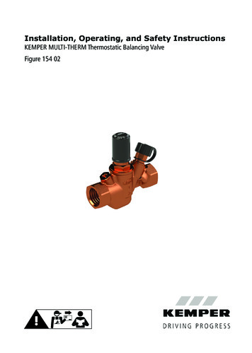
4.3 Insert a temperature probePull the black cap on the pocket for temperature probe and insert the optionalBalancing headavailable temperature dial indicator Part. No.T51001550000100.Marker arrowPlugAdjustment wheel8 /12 – K410015400002-00 / 04.2020Grub screwIsolating insert / pocketfor temperature probe
5Control Characteristic at set temperature of 136 F04.2020 / K410015400002-00 – 9 / 12
6Flow diagrams10 /12 – K410015400002-00 / 04.2020
04.2020 / K410015400002-00 – 11 / 12
Craig BoyceKemper Water Control Systems, Inc.518 Route 513, Suite BPO Box 195Califon, NJ 07830 USAPhone: 1 239 298 9273Email: Craig.Boyce@KemperWaterControl.comiGebr. Kemper GmbH Co. KGHarkortstaße 4D-57462 Olpe12 / 12 – K410015400002-00 / 04.2020Service-Hotline 49 2761 5400002-00 / 04.2020For more information, please contact:
KEMPER MULTI-THERM Thermostatic Balancing Valve Figure 154 02 ! 2 / 12 - K410015400002-00 / 04.2020 . For more information, please contact:\r\rCraig Boyce\rKemper Water Control Systems, Inc. \r518 Route 513, Suite B \rPO Box 195 \rCalifon, NJ 07830 USA \rPhone: 1 239 298 9273 \rEmail: Craig.Boyce@KemperWaterControl.com. Title: