Transcription
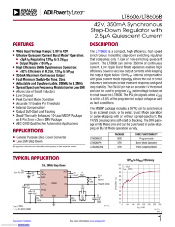
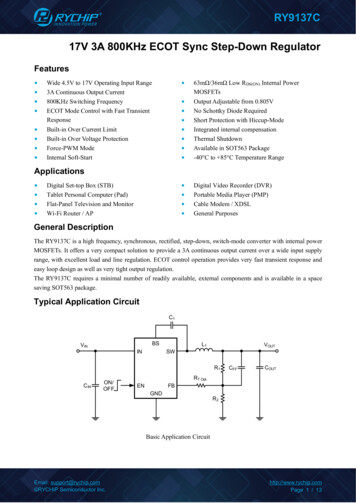
LT8610AX42V, 3.5A SynchronousStep-Down Regulator withOperation to 175 CDESCRIPTIONFEATURES100% Tested at 175 Cnn 2% Reference Accuracy Over –40 C to 175 C Rangenn Wide Input Voltage Range: 3.7V to 42Vnn Ultralow Quiescent Current Burst Mode Operationnn High Efficiency Synchronous Operationnn 91% Eff. at 0.5A, at 175 C, 3.3VOUT from 12VINnn 92% Eff. at 0.5A, at 175 C, 5VOUT from 12VINnn Adjustable and Synchronizable Frequency: 200kHzto 2.2MHznn No Thermal Shutdownnn Internal Compensationnn Output Soft-Start and Trackingnn Power Good Flagnn Small Thermally-Enhanced 16-Lead MSOP PackagennAPPLICATIONSnnOil and Gas ExplorationThe LT 8610AX is a compact, high efficiency, high speedsynchronous monolithic step-down switching regulatorrated to 175 C junction temperature. The LT8610AX is100% tested a 175 C. Top and bottom power switchesare included with all necessary circuitry to minimize theneed for external components. Low ripple Burst Modeoperation enables high efficiency across a wide range ofoutput currents while keeping the output ripple low. A SYNCpin allows synchronization to an external clock. Internalcompensation with peak current mode topology allowsthe use of small inductors and results in fast transientresponse and good loop stability. The EN/UV pin has anaccurate 1V threshold and can be used to program VINundervoltage lockout or to shut down the LT8610AX. Acapacitor on the TR/SS pin programs the output voltageramp rate during startup while the PG flag signals whenVOUT is within 9% of the programmed output voltageas well as fault conditions. The LT8610AX is available insmall 16-lead MSOP package with exposed pad for lowthermal resistance.L, LT, LTC, LTM, Linear Technology, the Linear logo and Burst Mode are registered trademarksof Linear Technology Corporation. All other trademarks are the property of their respectiveowners.TYPICAL APPLICATION3.3V Step-Down ConverterEfficiencyat 175 CEfficiencyat 175 C100VIN4.7µF0.1µF fSW 700kHz47µF 21210X7RVOUT3.3V3.5AEFFICIENCY (%)VIN3.7V TO 42V8610AX TA01aTA 175 C12VIN1001101001kLOAD CURRENT (mA)10k8610AX TA01b8610axfFor more information www.linear.com/LT8610AX1
LT8610AXABSOLUTE MAXIMUM RATINGSPIN CONFIGURATION(Note 1)VIN, EN/UV, PG.42VBIAS.30VFB, TR/SS Voltage .4VSYNC Voltage .6VOperating Junction Temperature Range (Note 2)LT8610AX. –40 to 175 CStorage Temperature Range.–65 to 150 CTOP 110917GNDFBPGBIASINTVCCBSTSWSWSWMSE PACKAGE16-LEAD PLASTIC MSOPθJA 40 C/W, θJC(PAD) 10 C/WEXPOSED PAD (PIN 17) IS GND, MUST BE SOLDERED TO PCBORDER #orderinfo)LEAD FREE FINISHTAPE AND REELPART MARKINGPACKAGE DESCRIPTIONTEMPERATURE RANGELT8610AXMSE#PBFLT8610AXMSE#TRPBF8610AX16-Lead Plastic MSOP–40 C to 175 CConsult LTC Marketing for parts specified with wider operating temperature ranges.For more information on lead free part marking, go to: http://www.linear.com/leadfree/For more information on tape and reel specifications, go to: http://www.linear.com/tapeandreel/. Some packages are available in 500 unit reels throughdesignated sales channels with #TRMPBF suffix.ELECTRICAL CHARACTERISTICSThe l denotes the specifications which apply over the full operatingtemperature range, otherwise specifications are at TA 25 C.PARAMETERCONDITIONSMINMinimum Input VoltageVIN Current in RegulationVOUT 0.97V, VIN 6V, Output Load 100μAVOUT 0.97V, VIN 6V, Output Load 1mAFeedback Reference VoltageVIN .9720.9700.9780.990UNITSOscillator FrequencyRT 60.4kl665700735kHzPG Upper Threshold Offset from VFBVFB Fallingl6912%PG Lower Threshold Offset from VFBVFB Risingl–12–9–6%Note 1: Stresses beyond those listed under Absolute Maximum Ratingsmay cause permanent damage to the device. Exposure to any AbsoluteMaximum Rating condition for extended periods may affect devicereliability and lifetime.Note 2: Devices are 100% tested at 175 C to the limits shown. For normaloperating temperature range specifications, please see the LT8610A/LT8610AB data sheet. The LT8610AX performance is based on theLT8610AB.2Note 3. The LT8610AX is guaranteed over the full –40 C to 175 Coperating junction temperature range. High junction temperatures degradeoperating lifetimes. Operating lifetime is derated at junction temperaturesgreater than 125 C. The LT8610AX has no thermal shutdown.8610axfFor more information www.linear.com/LT8610AX
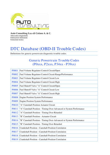
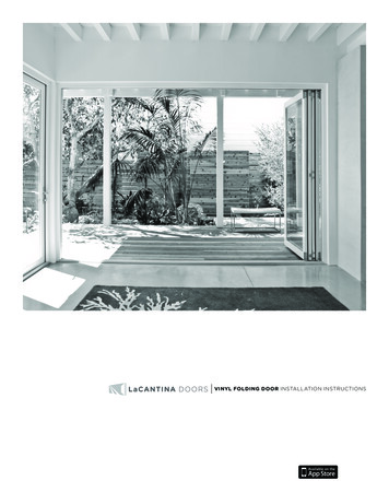
LT8610AXTYPICAL PERFORMANCE CHARACTERISTICSReferenceReference VoltageVoltageReferenceReference VoltageVoltage atat 175 C175C451000LOAD 0.5A100N 347µ 968.5σ 3.339096095030EFFICIENCY (%)97015940255075 100 125 150TEMPERATURE ( C)17520036VIN50403012VIN8024VIN70EFFICIENCY 0LOAD CURRENT (mA)15202530INPUT VOLTAGE (V)36VIN751k10k60100 200 300 400 500 600 700 800 900 1000LOAD CURRENT (mA)8610AX G06Power Up at 175 V/DIVPG2V/DIVSS2V/DIV10ms/DIV201024VINTA 175 C140580EN Cycling at 175 CTA 175 CFRONT PAGE APP3.3VOUT IN REGULATION180858610AX G05No Load Input Current at 175 C200TA 175 CfSW 700kHz6500.018610AX G0412VIN701060100 200 300 400 500 600 700 800 900 1000LOAD CURRENT (mA)10k9024VIN206509512VIN501kOUT100TA 175 CfSW 700kHz60110100LOAD CURRENT (mA)Efficiency at 175 C, VOUT 5VOUTEFFICIENCY (%)100TA 175 CfSW 700kHz900.18610AX G03EfficiencyEfficiency atat 175 C,175 C, VVOUT 5V5VOUT9500.018610AX G02Efficiency at 175 C, VOUT 3.3V100EFFICIENCY (%)24VIN60100950 955 960 965 970 975 980 985 990REFERENCE VOLTAGE (mV)8610AX G01INPUT CURRENT (uA)12VIN7020930920OUTTA 175 CfSW 700kHz80980NUMBER OF PARTSREFERENCE VOLTAGE (mV)990EfficiencyEfficiency atat 175 C,175 C, VVOUT 3.3V3.3V358610AX G08TA 175 C10ms/DIV8610AX G09408610AX G078610axfFor more information www.linear.com/LT8610AX3
LT8610AXPIN FUNCTIONSSYNC (Pin 1): External Clock Synchronization Input.Ground this pin for low ripple Burst Mode operation at lowoutput loads. Tie to a clock source for synchronization toan external frequency. Apply a DC voltage of 3V or higheror tie to INTVCC for pulse-skipping mode. When in pulseskipping mode, the IQ will increase to several hundred µA.Do not float this pin.SW (Pins 9, 10, 11): The SW pins are the outputs of theinternal power switches. Tie these pins together and connect them to the inductor and boost capacitor. This nodeshould be kept small on the PCB for good performance.TR/SS (Pin 2): Output Tracking and Soft-Start Pin. Thispin allows user control of output voltage ramp rate duringstart-up. A TR/SS voltage below 0.97V forces the LT8610AXto regulate the FB pin to equal the TR/SS pin voltage. WhenTR/SS is above 0.97V, the tracking function is disabledand the internal reference resumes control of the erroramplifier. An internal 2.2μA pull-up current from INTVCC onthis pin allows a capacitor to program output voltage slewrate. This pin is pulled to ground with an internal 230ΩMOSFET during shutdown and fault conditions; use a seriesresistor if driving from a low impedance output. This pinmay be left floating if the tracking function is not needed.INTVCC (Pin 13): Internal 3.4V Regulator Bypass Pin.The internal power drivers and control circuits are powered from this voltage. INTVCC maximum output current is 20mA. Do not load the INTVCC pin with externalcircuitry. INTVCC current will be supplied from BIAS ifVBIAS 3.1V, otherwise current will be drawn from VIN.Voltage on INTVCC will vary between 2.8V and 3.4V whenVBIAS is between 3.0V and 3.6V. Decouple this pin to powerground with at least a 1μF low ESR ceramic capacitorplaced close to the IC.RT (Pin 3): A resistor is tied between RT and ground toset the switching frequency.EN/UV (Pin 4): The LT8610AX is shut down when thispin is low and active when this pin is high. The hystereticthreshold voltage is 1.00V going up and 0.96V goingdown. Tie to VIN if the shutdown feature is not used. Anexternal resistor divider from VIN can be used to programa VIN threshold below which the LT8610AX will shut down.VIN (Pins 5, 6): The VIN pins supply current to the LT8610AXinternal circuitry and to the internal topside power switch.These pins must be tied together and be locally bypassed.Be sure to place the positive terminal of the input capacitor as close as possible to the VIN pins, and the negativecapacitor terminal as close as possible to the GND pins.NC (Pin 7): No Connect. This pin is not connected tointernal circuitry.4BST (Pin 12): This pin is used to provide a drive voltage,higher than the input voltage, to the topside power switch.Place a 0.1µF boost capacitor as close as possible to the IC.BIAS (Pin 14): The internal regulator will draw current fromBIAS instead of VIN when BIAS is tied to a voltage higherthan 3.1V. For output voltages of 3.3V and above this pinshould be tied to VOUT. If this pin is tied to a supply otherthan VOUT use a 1µF local bypass capacitor on this pin.PG (Pin 15): The PG pin is the open-drain output of aninternal comparator. PG remains low until the FB pin iswithin 9% of the final regulation voltage, and there areno fault conditions. PG is valid when VIN is above 3.4V,regardless of EN/UV pin state.FB (Pin 16): The LT8610AX regulates the FB pin to 0.970V.Connect the feedback resistor divider tap to this pin. Also,connect a phase lead capacitor between FB and VOUT.Typically, this capacitor is 4.7pF to 10pF.GND (Pin 8, Exposed Pad Pin 17): Ground. These pinsare the return path of the internal bottom-side switch andmust be tied together. Place the negative terminal of theinput capacitor as close to the GND pin and exposed padas possible. The exposed pad must be soldered to the PCBin order to lower the thermal resistance.8610axfFor more information www.linear.com/LT8610AX
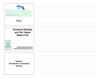
LT8610AXAPPLICATIONS INFORMATIONFor Application Information, Block Diagram, and Typical Performance Curves from –40 C to 150 C range, please seethe LT8610A/LT8610AB Series data sheet. The LT8610AX will perform similarly to the LT8610AB. The LT8610AXhas no thermal shutdown.PACKAGE DESCRIPTIONPlease refer to http://www.linear.com/product/LT8610AX#packaging for the most recent package drawings.MSE Package16-Lead Plastic MSOP, Exposed Die Pad(Reference LTC DWG # 05-08-1667 Rev F)BOTTOM VIEW OFEXPOSED PAD OPTION2.845 0.102(.112 .004)5.10(.201)MIN2.845 0.102(.112 .004)0.889 0.127(.035 .005)811.651 0.102(.065 .004)1.651 0.102 3.20 – 3.45(.065 .004) (.126 – .136)0.305 0.038(.0120 .0015)TYP160.50(.0197)BSC4.039 0.102(.159 .004)(NOTE 3)RECOMMENDED SOLDER PAD LAYOUT0.254(.010)0.35REF0.12 REFDETAIL “B”CORNER TAIL IS PART OFDETAIL “B” THE LEADFRAME FEATURE.FOR REFERENCE ONLY9NO MEASUREMENT PURPOSE0.280 0.076(.011 .003)REF16151413121110 9DETAIL “A”0 – 6 TYP3.00 0.102(.118 .004)(NOTE 4)4.90 0.152(.193 .006)GAUGE PLANE0.53 0.152(.021 .006)DETAIL “A”1.10(.043)MAX0.18(.007)SEATINGPLANE0.17 – 0.27(.007 – .011)TYP1234567 80.50(.0197)BSCNOTE:1. DIMENSIONS IN MILLIMETER/(INCH)2. DRAWING NOT TO SCALE3. DIMENSION DOES NOT INCLUDE MOLD FLASH, PROTRUSIONS OR GATE BURRS.MOLD FLASH, PROTRUSIONS OR GATE BURRS SHALL NOT EXCEED 0.152mm (.006") PER SIDE4. DIMENSION DOES NOT INCLUDE INTERLEAD FLASH OR PROTRUSIONS.INTERLEAD FLASH OR PROTRUSIONS SHALL NOT EXCEED 0.152mm (.006") PER SIDE5. LEAD COPLANARITY (BOTTOM OF LEADS AFTER FORMING) SHALL BE 0.102mm (.004") MAX6. EXPOSED PAD DIMENSION DOES INCLUDE MOLD FLASH. MOLD FLASH ON E-PAD SHALLNOT EXCEED 0.254mm (.010") PER SIDE.0.86(.034)REF0.1016 0.0508(.004 .002)MSOP (MSE16) 0213 REV F8610axfInformation furnished by Linear Technology Corporation is believed to be accurate and reliable.However, no responsibility is assumed for its use. Linear Technology Corporation makes no representation that the interconnectionof itsinformationcircuits as describedherein will not infringe on existing patent rights.For morewww.linear.com/LT8610AX5
LT8610AXRELATED PARTSPART NUMBERDESCRIPTIONCOMMENTSPACKAGELT1007XLow Noise 200 C Op AmpLow Noise, High Speed Precision Operational Amplifier8-Lead TO-5 Metal CanLT580X200 C, 2.5V Voltage ReferenceUltra Low Drift, Curvature Corrected Reference3-Lead TO-52 Metal CanLT581X200 C, 10V Voltage ReferenceUltra Low Drift, Curvature Corrected Reference3-Lead TO-39 Metal CanLT582X200 C, 5V Voltage ReferenceUltra Low Drift, Curvature Corrected Reference3-Lead TO-39 Metal Can68610axfLinear Technology Corporation1630 McCarthy Blvd., Milpitas, CA 95035-7417For more information www.linear.com/LT8610AX(408) 432-1900 FAX: (408) 434-0507 www.linear.com/LT8610AXLT 0416 PRINTED IN USA LINEAR TECHNOLOGY CORPORATION 2016
n 100% Tested at 175 C n 2% Reference Accuracy Over -40 C to 175 C Range n Wide Input Voltage Range: 3.7V to 42V n Ultralow Quiescent Current Burst Mode Operation n High Efficiency Synchronous Operation n 91% Eff. at 0.5A, at 175 C, 3.3VOUT from 12VIN n 92% Eff. at 0.5A, at 175 C, 5VOUT from 12VIN n Adjustable and Synchronizable .