Transcription
www.swagelok.comEl e ctr ic Tub e B e n derUser’s Manual
Table of ContentsOperator’s Safety Summary . . . . . . . . . . . . . . . . . . . . . . . . . . . . . . . . . . . . . . . . . . . . . . . . . . . . . . . . . . . . . . . . . . . . . . . 3Grounding and Extension Cord Information . . . . . . . . . . . . . . . . . . . . . . . . . . . . . . . . . . . . . . . . . . . . . . . . . . . . . . 3Statements . . . . . . . . . . . . . . . . . . . . . . . . . . . . . . . . . . . . . . . . . . . . . . . . . . . . . . . . . . . . . . . . . . . . . . . . . . . . . . . 3Symbols . . . . . . . . . . . . . . . . . . . . . . . . . . . . . . . . . . . . . . . . . . . . . . . . . . . . . . . . . . . . . . . . . . . . . . . . . . . . . . . . . 3Safety Features . . . . . . . . . . . . . . . . . . . . . . . . . . . . . . . . . . . . . . . . . . . . . . . . . . . . . . . . . . . . . . . . . . . . . . . . . . . . 4Tube Bender Technical Data . . . . . . . . . . . . . . . . . . . . . . . . . . . . . . . . . . . . . . . . . . . . . . . . . . . . . . . . . . . . . . . . . . . . . . . 5Tubing Information . . . . . . . . . . . . . . . . . . . . . . . . . . . . . . . . . . . . . . . . . . . . . . . . . . . . . . . . . . . . . . . . . . . . . . . . . . . . . . 5Tube Bender Components . . . . . . . . . . . . . . . . . . . . . . . . . . . . . . . . . . . . . . . . . . . . . . . . . . . . . . . . . . . . . . . . . . . . . . . . 6Digital Display Pendant . . . . . . . . . . . . . . . . . . . . . . . . . . . . . . . . . . . . . . . . . . . . . . . . . . . . . . . . . . . . . . . . . . . . . . . . . . . 6Error Message . . . . . . . . . . . . . . . . . . . . . . . . . . . . . . . . . . . . . . . . . . . . . . . . . . . . . . . . . . . . . . . . . . . . . . . . . . . . . . . . . . 6Assembling Components . . . . . . . . . . . . . . . . . . . . . . . . . . . . . . . . . . . . . . . . . . . . . . . . . . . . . . . . . . . . . . . . . . . . . . . . . 7Tubing LayoutSingle 90 Bend . . . . . . . . . . . . . . . . . . . . . . . . . . . . . . . . . . . . . . . . . . . . . . . . . . . . . . . . . . . . . . . . . . . . . . . . . . . 8Multiple 90 Bends (Measure-Bend Method) . . . . . . . . . . . . . . . . . . . . . . . . . . . . . . . . . . . . . . . . . . . . . . . . . . . . . 8Multiple 90 Bends (Premeasure Method) . . . . . . . . . . . . . . . . . . . . . . . . . . . . . . . . . . . . . . . . . . . . . . . . . . . . . . . 9Making Offset Bends . . . . . . . . . . . . . . . . . . . . . . . . . . . . . . . . . . . . . . . . . . . . . . . . . . . . . . . . . . . . . . . . . . . . . . 10Springback . . . . . . . . . . . . . . . . . . . . . . . . . . . . . . . . . . . . . . . . . . . . . . . . . . . . . . . . . . . . . . . . . . . . . . . . . . . . . . . . . . . 11Bending . . . . . . . . . . . . . . . . . . . . . . . . . . . . . . . . . . . . . . . . . . . . . . . . . . . . . . . . . . . . . . . . . . . . . . . . . . . . . . . . . . . . . . 11Bending Using Auto Bend . . . . . . . . . . . . . . . . . . . . . . . . . . . . . . . . . . . . . . . . . . . . . . . . . . . . . . . . . . . . . . . . . . . . . . . .12Troubleshooting . . . . . . . . . . . . . . . . . . . . . . . . . . . . . . . . . . . . . . . . . . . . . . . . . . . . . . . . . . . . . . . . . . . . . . . . . . . . . . . . 12Roller Adjustment Screws . . . . . . . . . . . . . . . . . . . . . . . . . . . . . . . . . . . . . . . . . . . . . . . . . . . . . . . . . . . . . . . . . . . . . . . . 13Roller Alignment . . . . . . . . . . . . . . . . . . . . . . . . . . . . . . . . . . . . . . . . . . . . . . . . . . . . . . . . . . . . . . . . . . . . . . . . . . . . . . . 13Maintenance . . . . . . . . . . . . . . . . . . . . . . . . . . . . . . . . . . . . . . . . . . . . . . . . . . . . . . . . . . . . . . . . . . . . . . . . . . . . . . . . . . 14Warranty Information . . . . . . . . . . . . . . . . . . . . . . . . . . . . . . . . . . . . . . . . . . . . . . . . . . . . . . . . . . . . . . . . . . . . . . . . . . . . 16SAVE THESE INSTRUCTIONS!–2–
Operator’s Safety SummaryREAD AND UNDERSTAND THIS MANUAL BEFORE USING BENDER. This device is electrically powered and mustbe operated in a safe environment to avoid risk of fire, explosion, or electric shock.Grounding and Extension Cord Information Bender MUST be grounded to guard against electrical shock. It is equipped with a three-wire conductor andthree-prong plug to fit a grounded receptacle. NEVER CONNECT THE GREEN OR GREEN/YELLOW WIRE TO A LIVE TERMINAL! Use only three-wire extension cords that have three-prong grounding-type plugs and three-pole receptacles. The extension cord wire size must meet the following specifications:– For 0 to 50 ft (0 to 15 m), the recommended minimum wire gauge is #12 AWG (2.5 mm).– For 50 to 100 ft (15 to 30 m), the recommended minimum wire gauge is #10 AWG (4.0 mm).StatementsCaution!Statements that identify conditions or practices that could result in damage to the equipment orother propertyWarning!Statements that identify conditions or practices that could result in personal injuries or loss of life SymbolsCaution!Indicates cautionary information.Warning!Indicates that voltage greater than 30V (ac) is present.Warning!PINCH POINTS. Keep hands, loose clothing, and long hair away from moving parts. Serious injury canoccur.Warning!KEEP DRY. Do not expose the equipment to water or wet locations. Warning!FIRE OR EXPLOSION. Do not use equipment in a combustible or explosive atmosphere. Flammableliquids or gases could ignite.Warning!EYE PROTECTION. Eye protection must be worn while operating or working near the equipment.–3–
Safety FeaturesEmergency Stop ButtonStops rotation of bend shoe andclears allsettings. Auto bend function will requirereprogramming.Circuit BreakerDisconnects power from outside source.Clears all settings.Receptacle withCord/Socket LockPlug in power cord. Tighten screw on cord/socket lock to secure power cord.–4–
Tube Bender Technical DataBending Range:1 to 110 , in 1 increments. Bending in excess of 110 may damage bender.Dimensions:Vertical Position: 44 in. (112 cm) high, 29 in. (74 cm) wide, 30 in. (76 cm) deepWeight:420 lb (191 kg)Power Requirements: MS-TBE-1115 V (ac) 50/60 HzMaximum current: 13 AMS-TBE-2230 V (ac) 50/60 HzMaximum current: 7 ATubing Information All tubing should be free of scratches and suitable for bending. Bends 1, 1 1/4, 1 1/2, and 2 in.; 25, 32, 38, and 50 mm OD tubing in a variety of wall thicknesses. Carbon steel tubing should be soft (annealed), seamless (ASTM A179), or welded and drawn, DIN 2391-1 andDIN‑2391-2 or equivalent, with a hardness of 72 HRB, HV (VPN) 130 or less. Stainless steel tubing should be fully annealed, seamless, or welded and drawn, meeting ASTM A269, ASTM A213,EN‑ISO‑1127, or equivalent specification, with a hardness of 80 HRB, HV (VPN) 180 or less. The following information for bending annealed tubing is listed below in Table 1: bend radius, wall thickness limits,and minimum straight length required to make a 90 bend using the tail roller.Table 1 – Min/Max Wall Thickness ➀TubeODin.11 1/41 1/22➀Dimensions, in.MinLengthBendRadiusCarbonSteelStainlessSteel20 1/222 3/425 eODmm25323850Dimensions, 02.0/4.02.2/4.53.0/5.0See the Swagelok Tubing Data catalog for suggested tubing wall thickness for use with Swagelok tube fittings.READ AND BECOME FAMILIAR WITH OPERATING INSTRUCTIONSBEFORE BENDING TUBING!This bender can be used in thevertical or horizontal position.Before using bender make sure rollers and shoe grooves are in line.See Roller Alignment (page 13).–5–
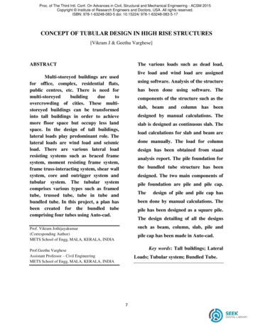
Tube Bender ComponentsRoller TowersTube ClampsBend ShoeBend ShoeRetaining PinRemovable Tail RollerRollerTowerFixed Tail RollerRollerAdjustmentScrewsBridge OpeningBridgeHandle LockError MessageDigital Display PendantLED Display – Displays degrees of rotation.An “E1” in pendant display indicatesthat the motor has stopped. Removeany obstruction in bend shoe, and retrythe BEND or UNLOAD function.Bend – Rotates bend shoe clockwise.Jog – Rotates bend shoe clockwise in1 increments.Unload – Rotates bend shoe counterclockwise.Zero Set – Resets pendant display to “0.”Bend Set – Stores a bend in memory. Indicatorlight on display (center decimal point) will flash toconfirm bend is stored.Auto Bend – Rotates bend shoe to the anglestored in memory. Auto bend indicator light (rightdecimal point) remains on when bending withmemory.Override – Overrides the auto bend modewithout erasing memory.–6– CAUTION!Pressing color key padfunctions on the pendantcauses bend shoe to rotate.
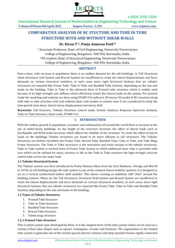
Assembling ComponentsUp Position1 1/2 in.1. Select and install proper tail rollers. To bend 1 1/2 in. (38 mm) ODtubing, use the fixed tail roller in the up position. For 2 in. (50 mm) ODtubing, use the fixed tail roller in the down position. (See Figure 1.)(38 mm)DownPosition2 in.To bend 1 in. (25 mm) OD tubing, use the 1 in. (25 mm) removable tailroller, securing pin in lower pin hole (up position). For 1 1/4 in. (32mm) OD tubing, use the 1 1/4 in. (32 mm) removable tail roller, securingpin in upper pin hole. Align roller with the inside of the unit. (See Figure2.)(50 mm)2. Select proper roller tower; the size is indicated on roller tower. To install,lift and hold the handle lock. Insert the roller tower into proper bridgeopening so that the size indicator faces you. Allow roller tower to leanagainst tail roller. (See Figure 3.)Figure 13. Select proper tube clamp; the size is indicated on clamp face. Locatethe tube size on the bend shoe, and attach the tube clamp with pin,making sure the size identification faces out. (See Figure 4.)UpperPin Hole1 1/4 in.(32 mm)LowerPin Hole1 in.4. Make sure the circuit breaker is switched to the ON position and theEMERGENCY STOP button is not engaged.(25 mm)5. Plug the unit into an appropriate power source. The display on thependant will illuminate.Figure andleLockFigure 3PinTubeClampSizeIndicatorFigure 4–7–
Tubing LayoutWith this bender, you can form single, offset,other bends. This section contains information for measuring andFirst and90 Bend.epsmarking the tubing prior to bending. NOTE: Make all marks 360 around the tubing.Measurement LengthReferenceMarkMeasurementMarkBend DeductionDistanceBendMarkIllustration 1 – Single Bend 90 Single 90 Bend1. Place a reference mark at the end of the tubing from which your measurement begins.2. From the reference mark at the end of the tubing, measure the desired length for the bend. Make a measurementmark on the tubing.Second 90 Bend.eps3. Subtract the bend deduction distance (see Table 2 on page 9) from the measurement mark and make a bendmark. (The bend deduction distance is a length that compensates for the bender and tube clamp design.)4. To bend tubing, see Bending on page 11.Multiple 90 BendsFirst Measurement Mark18 in.The Measure-Bend Method1. Follow Steps 1 to 4 above for a Single 90 Bend.2. Using the center line of the previous 90 bend as yoursecond reference mark, repeat Steps 2 to 4 for the second90 bend.EXAMPLE: Using 1 1/2 in. OD tubing, make two 90 bendswith measured length distances of 18 in. between bend marks.(See Illustrations 2 and 3.)1. From the reference mark at the end of the tubing, measure18 in. and make a measurement mark.2. The bend deduction distance for 1 1/2 in. OD tubing inTable 2 is 9 7/8 in.3. 18 in. – 9‑7/8 in. 8‑1/8 in. Make the first bend mark at8‑1/8 in.4. Bend tubing.5. From the center line of the first 90 bend, measure 18 in.and make a measurement mark.6. The bend deduction distance for 1 1/2 in. OD tubing inTable 2 is 9‑7/8 in.7. 18 in. – 9‑7/8 in. 8‑1/8 in. Make the second bend markat 8‑1/8 in. from the center line of the first 90 bend.8. Bend tubing.ReferenceMarkBend DeductionDistance9 7/8 in.BendMarkCenterLine1 1/2 in. OD TubingIllustration 2 – First 90 BendBendMarkBend DeductionDistance9‑7/8 in.SecondMeasurementMark18 in.Note: Follow the above steps when using metricmeasurements.Illustration 3 – Second 90 Bend–8–
Multiple 90 BendsThe Premeasure Method1. Follow Steps 1 to 3 for a Single 90 Bend. (See page 8.)2. From the reference mark at the end of the tubing, measure the desired length for the second bend and make ameasurement mark.3. Subtract the bend deduction distance (see Table 2) and the adjustment factor (see Table 3) from the secondmeasurement mark, and make the second bend mark.Second MeasurementLength 36 in.First MeasurementLength 18 in.GainAdjustmentFactor2 9/16 in.Bend Deduction Distance9‑7/8 in.ReferenceMarkBendMarkBend DeductionDistance9‑7/8 in.BendMarkIllustration 4 – Multiple 90 BendsEXAMPLE: Using 1 1/2 in. OD tubing, make two 90 bendswith a measured length distance of 18‑in. between bendmarks. (See Illustration 4.)Table 2 – Bend Deduction DistanceTubeODin.11 1/41 1/221. From the reference mark at the end of the tubing,measure 18 in. and make a measurement mark.2. The bend deduction distance for 1 1/2 in. OD tubing inTable 2 is 9‑7/8 in.3. 18 in. – 9‑7/8 in. 8‑1/8 in. Make the first bend markat 8‑1/8 ubeODmm25323850BendDeductionmm1772132473187. 36 in. – 9‑7/8 in. – 2‑9/16 in. 23‑9/16 in.4. Add the first and second measurement lengths. 18 in. 18 in. 36 in.8. From the reference mark at the end of the tubing,measure 23‑9/16 in. and make a second bend mark.5. From the reference mark at the end of the tubing,measure 36 in. and make a second measurement mark.9. Bend tubing.6. The bend deduction distance for 1 1/2 in. OD tubing is9‑7/8 in., and the adjustment factor for a 90 bend inTable 3 is 2‑9/16 in.Note: Follow the above steps when using metricmeasurements.Table 3 – Gain Factors for 0 to 90 Bends0 1 2 3 4 5 6 7 8 9 0 00030.000310 0.003120 01000.011130 02540.027640 05270.056250 09630.101860 16220.170370 25820.269980 39550.412190 0.4292—————————Example: The gain factor for a 90 bend is 0.4292.To calculate the gain for 90 bend multiply the gain factor times the bend radius.Example: 0.4292 3 6 in. 2.58, or about 2‑9/16 in. gain–9–
Making Offset BendsNOTE: Make all marks 360 around the tubing.1. Make a reference mark at the end of the tubing from whichyour measurement begins.2. From the reference mark at the end of the tubing, measurethe desired length for the bend. Make a measurementmark on the tubing.3. Subtract the clamp distance (see Table 4) from the firstmeasurement mark and make a bend mark.4. Determine the length of tubing (L) consumed in the offset.See Table 5 or use one of the offset bend allowancesreferred to in Table 6. (See Illustration 5.)5. From the first bend mark, measure the distance requiredfor the offset bend allowance and make a second bendmark.6. Check for proper bend direction and tube orientation. Tobend tubing, see Bending on page 11.LOEIllustration 5 – Tubing Length OffsetTable 4 – Clamp DistanceTubeTubeClampODODDistancemmin.in.2512 1/4321 1/42 3/4381 1/23 1/25024(Clamp distance only applies to offset bends.)Clamp Distance 3 1/2 in.First Measurement Length14 in.First MeasurementMarkReferenceMarkFirstBend MarkClampDistancemm577089102Second Bend MarkDistance to CenterIllustration 6 – Offset BendsEXAMPLE: Using 1 1/2 in. OD tubing, make an offset bendbeginning 14 in. from the end of the tube with a 20‑in. offsetdimension (O) and a 30 offset angle (E). (See Illustration 6.)Table 5 – Offset Bend CalculationsE30 Offset1. From the reference mark at the end of the tubing, measure14 in. and make a measurement mark.2. The clamp distance for 1 1/2 in. OD tubing in Table 4 is3‑1/2 in.3. 14 in. – 3‑1/2 in. 10‑1/2 in. Make the first bend mark at10‑1/2 in.4. The 20 in. offset bend is not in Table 5. Calculate the centerto-center distance by multiplying 20 in. by the factor in Table6 for a 30 offset, 2.000. 20 in. 3 2.000 40 in.5. From the first bend mark, measure 40 in. and make thesecond bend mark.6. Bend tubing.Note: Follow the above steps when using metricmeasurements.Table 6 – Offset Bend AllowanceEAngle.LLength30 2.000 X O (offset)45 1.414 X O (offset)60 1.154 X O (offset)E45 OffsetE60 OffsetMaxLMaxLMaxLOTube Center Tube Center Tube CenterOffsetDimension OD to Center OD to Center OD to Centerin.in.in.in.in.in.in.6121 1/28 3/81781611‑1/41 0‑3/4E30 OffsetE45 OffsetE60 OffsetMaxLMaxLMaxLOTube Center Tube Center Tube CenterOffsetDimension OD to Center OD to Center OD to 6462450900636519– 10 –
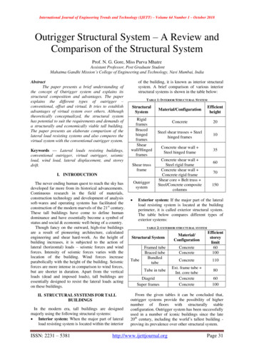
SpringbackBending the tubing approximately 3 beyond the desired angle isnecessary to compensate for tubing springback.NOTE: This is an approximate value. Tubing springback characteristicsdiffer due to size, wall thickness, and material.Warning!MOVING PARTS.Figure 5 1 1/4 and 2 in. (32 and 50 mm)Reference NotchBending1. Press the BEND or UNLOAD function key. Rotate the bend shoeuntil the proper reference notch on the bend shoe is aligned with thepointer on the faceplate. (See Figures 5 and 6.) Note the differencein appearance of the bend shoe in each figure. The tube clampshould hang vertically from the bend shoe.NOTE: If the bend shoe stops at 110 or – 99 , reset the pendantdisplay by pressing the ZERO SET function key. Then, press theBEND or UNLOAD function key to rotate bend shoe.2. Insert tubing through tube clamp with reference mark toward the left(see Tubing Layout, page 8), making sure tubing is positioned overtower and tail rollers. Press the JOG function key until tubing restson tail roller and fits tightly. Press the ZERO SET function key. Thisprocess ensures the bender is set correctly for bending.3. Press the UNLOAD function key until the tubing can be moved byhand. (Display will read approximately –2.)Figure 6 1 and 1 1/2 in. (25 and 38 mm)Reference Notch4. Slide tubing to align the bend mark with the left edge of the tubeclamp. (See Figure 7.)5. Lock the roller tower by pushing the handle lock down until the rollertower stops firmly against bridge. (See Figure 8.)6. To bend, press and hold the BEND or JOG function key untilthe desired angle is displayed. The JOG function key will bendin 1 increments. Release the key to stop the bend shoe. Addapproximately 3 to allow for springback.CAUTION! Bending in excess of 110 may damage tubing and bender.7. To remove tubing, stand clear of the handle lock, and press andhold the UNLOAD function key (approximately 5 ) until roller towerunlocks by lifting slightly. Lift the handle lock and allow roller towerto lean against tail roller. Remove tube clamp and tubing. Inspect thetubing bend; if wrinkling, ovality, or sidemarking has occurred, seeTroubleshooting on page 12.Bend Mark Aligned withLeft Edge of ClampFigure 7Roller Tower StopsAgainst BridgeFigure 8– 11 –
Bending Using Auto BendUse the auto bend feature to program a bend angle into the bender’smemory for applications where a single bend angle must be repeated.NOTE: A bend setting will be stored in memory until power isdisconnected or a new bend is set.1. Follow steps 1–3 under Bending (see page 11), then slide tubingcompletely away from tube clamp and bend shoe.2. Press the BEND or JOG function key until the desired angle isdisplayed. Add approximately 3 to allow for springback. Press theBEND SET function key to store the bend angle. The BEND SET light(center decimal point) on the display pendant will flash momentarily.Press the UNLOAD function key until the display reads approximately–2.3. Slide tubing through tube clamp and align the bend mark with the leftedge of the tube clamp. (See Figure 9.)4. Lock the roller tower by pushing the handle lock down until the rollertower stops firmly against bridge. Press the AUTO BEND function key.The AUTO BEND indicator light (right decimal point) will illuminate.5. Press and hold the BEND function key. The bend shoe will rotate untilthe set angle is reached.6. Follow step 7 under Bending.Figure 9NOTE: The auto bend function may be temporarily disabled to allow forbending of different angles, while maintaining the pre-set bend angle inmemory. To disengage the auto bend function, either:1. Press the AUTO BEND function key. The AUTO BEND indicator light willturn off, and the auto bend is disengaged. To reactivate the auto bendfunction, press the AUTO BEND function key. The indicator light willilluminate.2. Press the OVERRIDE AUTO BEND function key to temporarily overrideauto bend function. The AUTO BEND indicator light will flash and theauto bend function is temporarily disengaged. To reactivate the autobend function, press the OVERRIDE AUTO BEND function key. Theindicator light will stop flashing.TroubleshootingBender adjustments can be made if any of the following conditions are encountered. See page 13 for specificinstructions.ConditionPotential CauseSolutionSidemarkingRollers not aligned withbend shoeAlign rollers by turning roller alignment screws.Oversize tubingTurn roller adjustment screws counterclockwise inquarter-turn increments until condition clears.Excess roller pressureWrinklingUndersize tubingTurn roller adjustment screws clockwise inquarter-turn increments until condition clears.Insufficient rollerpressureOvalityUndersize tubingTurn roller adjustment screws clockwise inquarter-turn increments until condition clears.Insufficient rollerpressure– 12 –
Roller Adjustment ScrewsThe two roller adjustment screws on the left side of the bender(see Figure 10) change the pressure applied to the tubing. Thefactory setting (as viewed from the front) for these screws is thegap measured between the top of the bender frame leg and thebottom of the screw blocks.RollerAdjustmentScrewsOriginalFactory SettingFigure 10Notes: When the roller adjustment is changed to compensate for under or oversized tubing, return the roller screws to theiroriginal factory setting before bending a new length or lot of tubing. ZERO SET may need to be re-established. (See Bending, page 11, step 2.) Set the roller adjustment screws evenly to keep the bridge assembly level.Roller AlignmentThe two roller alignment screws, located on the rear side plate of the bridge assembly (see Figure 11), allow adjustmentof the bridge assembly to keep the roller towers and bend shoe aligned. Misalignment can lead to sidemarking.To Check Alignment: Viewing the bender from the side, look between the roller towers and thebend shoe. If the roller tower appears to be misaligned with the bendshoe, loosen the lock nuts on the roller alignment screws with a 9/16 in.wrench.RollerAlignmentScrews Using a 3/16 in. hex key, turn the roller alignment screws until the rollertower aligns with the bend shoe. Tighten the lock nuts. Always set the roller alignment screws evenly to keep the bridgeassembly parallel with the bend shoe.Figure 11– 13 –
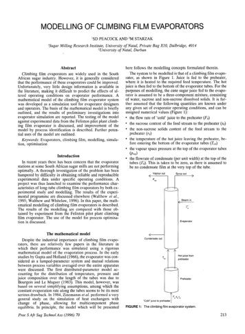
MaintenanceIf this bender is subjected to flooding, severe impact, fire, or otherextreme conditions, it should be inspected thoroughly by a trainedtechnician before use.Front ChainThe front chain requires no routine adjustment. However, it will stretchslightly after making the first 10 to 20 bends of 1 1/2 or 2 in.; or 38 or50 mm OD heavy wall tubing. If there is any slack in the chain:Figure 121. Disconnect the bender from the power source and remove the rollertower.2. Remove the bend shoe retaining pin. (See Figure 12.)3. Rock the bend shoe gently and pull forward until it clears drive lugs.Remove the bend shoe. Caution!Bend shoe weight is 33 lb (15 kg)4. Remove the long pin on the right side of the bridge assembly. (SeeFigure 13.)Figure 135. Unhook both springs from the left side of the bridge assembly, andremove the bridge assembly. (See Figure 14.)6. Remove the front cover, exposing the front chain. (See Figure 15.)7. Loosen the adjusting bolt, and rotate cam clockwise until the chain isfree of slack. Retighten the adjusting bolt. (See Figure 16.)8. Reassemble the cover, bridge assembly, and bend shoe.Lubrication Chains do not require lubrication under normal work conditions. Forcorrosive environmental conditions, a 90 weight oil may be used.Figure 14 Lubricate rollers and pivot points with a light machine oil asnecessary.Figure 15AdjustingBoltFigure 16– 14 –
– 15 –
Warranty InformationSwagelok products are backed by The Swagelok LimitedLifetime Warranty. For a copy, visit swagelok.com or contactyour authorized Swagelok representative.Swagelok—TM Swagelok Company 1999, 2002, 2004 Swagelok CompanyPrinted in U.S.A.December 2004, R5MS-13-138
Feb 16, 2011 · 2. Select proper roller tower; the size is indicated on roller tower. To install, lift and hold the handle lock. Insert the roller tower into proper bridge opening so that the size indicator faces you. Allow roller tower to lean against tail roller. (See Figure 3.) 3. Select prope