Transcription
Proc. of The Third Intl. Conf. On Advances in Civil, Structural and Mechanical Engineering - ACSM 2015Copyright Institute of Research Engineers and Doctors, USA .All rights reserved.ISBN: 978-1-63248-083-5 doi: 10.15224/ 978-1-63248-083-5-17CONCEPT OF TUBULAR DESIGN IN HIGH RISE STRUCTURES[Vikram J & Geethu Varghese]ABSTRACTThe various loads such as dead load,live load and wind load are assignedMulti-storeyed buildings are usedfor office, complex, residential flats,public centres, etc. There is need formulti-storeyedbuildingduetoovercrowding of cities. These multistoreyed buildings can be transformedinto tall buildings in order to achievemore floor space but occupy less landspace. In the design of tall buildings,lateral loads play predominant role. Thelateral loads are wind load and seismicload. There are various lateral loadresisting systems such as braced framesystem, moment resisting frame system,frame truss-interacting system, shear wallsystem, core and outrigger system andtubular system. The tubular systemcomprises various types such as framedtube, trussed tube, tube in tube andbundled tube. In this project, a plan hasbeen created for the bundled tubecomprising four tubes using Auto-cad.using software. Analysis of the structurehas been done using software. Thecomponents of the structure such as theslab, beam and column has beendesigned by manual calculations. Theslab is designed as continuous slab. Theload calculations for slab and beam aredone manually. The load for columndesign has been obtained from staadanalysis report. The pile foundation forthe bundled tube structure has beendesigned. The two main components ofpile foundation are pile and pile cap.Thedesign of pile and pile cap hasbeen done by manual calculations. Thepile has been designed as a square pile.The design detailing of all the designssuch as beam, column, slab, pile andProf. Vikram Jothijayakumar(Corresponding Author)METS School of Engg, MALA, KERALA, INDIApile cap has been made in Auto-cad.Key words: Tall buildings; LateralProf.Geethu VargheseAssistant Professor – Civil EngineeringMETS School of Engg, MALA, KERALA, INDIALoads; Tubular system; Bundled Tube.7
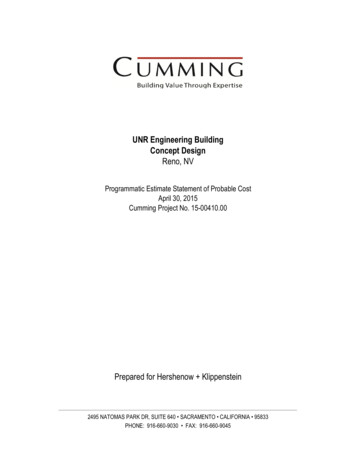
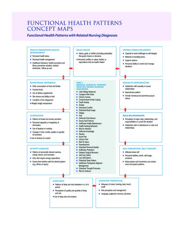
Proc. of The Third Intl. Conf. On Advances in Civil, Structural and Mechanical Engineering - ACSM 2015Copyright Institute of Research Engineers and Doctors, USA .All rights reserved.ISBN: 978-1-63248-083-5 doi: 10.15224/ 978-1-63248-083-5-17I.diaphragm orINTRODUCTIONA multi-storey building is a building that hasmultiple floors above ground.Multi-storeybuildings aim to increase the floor area of thebuilding without increasing the area of the land. Themulti-storey building can be transformed to tallbuilding to increase the floor space further more. Abuilding whose height creates different conditions in thedesign, construction, and use than those that exist incommon buildings of a certain region and period. Thecollector or drag member. Theyare built in wood, concrete and masonry.The outrigger systems may be formed in anycombination of steel, concrete, or compositeconstruction. These outriggers serve to reducethe overturning moment in the core that wouldotherwise act as a pure cantilever, and totransfer the reduced moment to columnsoutside the core by way of a tension-tall building design is influenced by the lateral loadscompression couple, which takes advantage ofsuch as wind, seismic,etc.the increased moment arm between thesecolumns. This system reduces the associateda. Lateral Load Resisting Systemspotential core uplift forces.Braced frames are cantilevered verticaltrusses resisting lateral loads primarily through theaxial stiffness of the frame members. The momentresisting frame consists of horizontal and verticalmembers rigidly connected together in a planar gridform which resists lateral loads primarily throughthe flexural stiffness of the members. Verticaltrusses alone may provide resistance for buildingsof up to about 20 stories depending on the height toFigure 1. Types of Framesb. Tubular Systemswidth ratio of the system. Shear trusses, whenThe tube is the name given to the systemscombined with moment resisting frames , produce awhere in order to resist lateral loads (wind,frame-truss interacting system.seismic, etc.) a building is designed to act like aShear walls are a type of structuralsystem that provides lateral resistance to abuilding or structure. They resist "in-plane" loadsthat are applied along its height. The applied loadis generally transferred to the wall by athree-dimensional hollow tube, cantileveredperpendicular to the ground. The system wasintroduced by Fazlur Rahman Khan. Tubeframe construction was first used in theDeWitt-Chestnut Apartment Building, designedby Khan and completed in Chicago in 1963.8
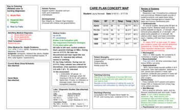
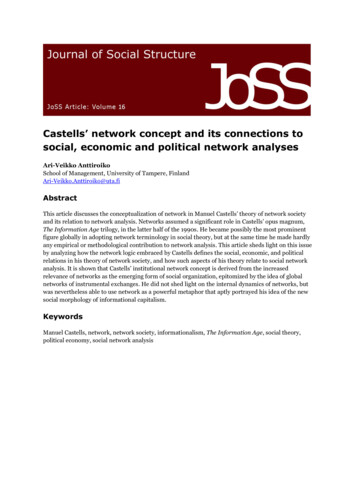
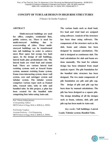
Proc. of The Third Intl. Conf. On Advances in Civil, Structural and Mechanical Engineering - ACSM 2015Copyright Institute of Research Engineers and Doctors, USA .All rights reserved.ISBN: 978-1-63248-083-5 doi: 10.15224/ 978-1-63248-083-5-17The system can be constructed using steel,but with comparatively fewer and farther-spacedconcrete,exterior columns.orcompositeconstruction(thediscrete use of both steel and concrete). It canbe used for office, apartment and mixed-usebuildings.Tube-In-Tube StructuresThis is a type of framed tube consistingMost buildings in excess of 40 stories constructedof an outer-framed tube together with ansince the 1960s are of this structural type.internal elevator and service core. The exteriortube and the interior tube are designed to actII.a.TYPES OF TUBE STRUCTUREtogether. The exterior tube has relatively largeFramed Tubewidth and hence it is designed to resist theThe organization of the framed tube systementire bending moment caused by lateral forces.is generally one of the closely spaced exteriorThe interior tubes are designed to carry shearcolumns and deep spandrel beams rigidlyproduced by the lateral forces. This type ofconnected together, with the entire assemblagestructures is also called as Hull (Outer tube)continuous along each façade and around theand Core (Inner tube) structures.building corners. The system is a logicalextension of moment resisting frame whereby thebeam and column stiffness are ons and increasing the member depths.b.Trussed Tube(a)framed tube(b)trussed tube(c)tube in tubeIn trussed tube structure, the exterior faceFigure 2. Types of tube structurecombines vertical, horizontal and diagonalmembers all of which are rigidly connected. Thediagonal members carry gravity loads as well aslateral loads. The external tube resists entireshear as well as bending and the interior structurecarries only gravitational loads. It is also knownas the braced tube, it is similar to the simple tube9c. Bundled TubeThe bundled tube system can bevisualised as an assemblage of individual tubesresulting in multiple cell tube to resist thelateral loads. The increase in stiffness isapparent. The system allows for the greatest
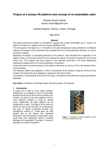
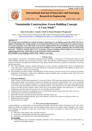
Proc. of The Third Intl. Conf. On Advances in Civil, Structural and Mechanical Engineering - ACSM 2015Copyright Institute of Research Engineers and Doctors, USA .All rights reserved.ISBN: 978-1-63248-083-5 doi: 10.15224/ 978-1-63248-083-5-17height and the most floor area. This structuralbuilding can be designed to resist lateral loadsform was used in the Sears Tower inby designing it as a hollow cantileverChicago.The bundle tube design was not onlyperpendicular to the ground.highly efficient in economic terms, but it wasalso "innovative in its potential for versatileThis exterior framing is designed sufficientlystrong to resist all lateral loads on the building,formulation of architectural space.thereby allowing the interior of the building toPLAN AND ELEVATIONbe simply framed for gravity loads. InteriorA plan has been created for the bundledcolumns are comparatively few and located attube structure comprising of four tubes havingthe core. The distance between the exterior anda plinth area of 63.6m by 63.6m. The elevationthe core frames is spanned with beams orof the structure consists of G 70 storeys withtrusses and intentionally left column-free. Thisstorey height as 3.5m.maximizes the effectiveness of the perimetertube by transferring some of the gravity loadswithin the structure to it and increases itsability to resist overturning due to lateral loads.Horizontal loads (primarily wind) are supportedby the structure as a whole.IV.STAAD-PRO APPLICATIONThe staad-pro software is applied forFigure 3. Plan of bundled tube using CADDIII.our project. Using staad-pro the modeling ofthe bundled tube structure is done for seventyDESIGN CONCEPTstoreys. The member property and supportThe frame tube concept is the rigid connectioncondition are assigned. The self weight of theof closely spaced exterior columns and deepstructure is assigned. The live load is assignedspandrel beams. This system is a logicalfor all the floors. The wind load is calculatedextension of moment resisting frame. The threefor Coimbatore zone. The analysis of the entiredimensional structural system utilizes the entirestructure is done. The results obtained are usedbuilding inertia to resist lateral loads. The tubefor design.system concept is based on the idea that a10
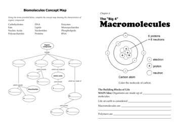
Proc. of The Third Intl. Conf. On Advances in Civil, Structural and Mechanical Engineering - ACSM 2015Copyright Institute of Research Engineers and Doctors, USA .All rights reserved.ISBN: 978-1-63248-083-5 doi: 10.15224/ 978-1-63248-083-5-17WIRE FRAME MODELV.CONCLUSIONA plan for the bundled tube iscreated using Auto-cad. The modeling of thebundled tube structure is done using staad pro.The loads are assigned and analysis of the frameis done. The elements such as slab, beam andcolumn are designed manually. The design ofFigure 4. Shear diagram of a floorpile and pile cap is done by manual calculations.Not only tube structure, any tall building ormulti-storeyed building is a better option forreduction of land use. In tube structure and otherskyscrapers the curtain walls are used. Thisreduces the cladding cost. This kind of buildingconstruction improves the infrastructure of thecountry.Figure 5. Bending moment diagram of a floorReferences[1] J. J. Connor, Introduction to Structural MotionControl, New York: Prentice Hall, 2003.[2] M. M. Ali and K. Moon, “Structural developments intall buildings: Currents trends and future prospects,”Architectural Science Review, vol. 50, no. 3, pp. 205-223,2007.[3]K.Moon, “Stiffness-based design methodology forsteel braced tube structures: A sustainable approach,”Engineering Structures, vol. 32, pp. 3163-3170, 2010.[4] K. Moon, J. J. Connor, and J. E. Fernandez, “Diagridstructural systems for tall buildings: characteristics andmethodology for preliminary design,” The StructuralDesign of Tall and Special Buildings, vol. 16, no. 2, pp.205-230, 2007.[5]B. Smith and A. Coull, Tall Building Structures:Analysis and Design,New York: Wiley, 1991.[6]E. Simiu and R. H. Scanlan, Wind Effects onStructures: Fundamentals and Applications to Design, 3rdEdition, New York: Wiley, 1996.Figure 6. Beam stress diagram of a floorFigure 7. Displacement diagram of a floor11
11.01.2016 · structures is also called as Hull (Outer tube) and Core (Inner tube) structures. (a)framed tube(b)trussed tube(c)tube in tube Figure 2. Types of tube structure c. Bundled Tube The bundled tube system can be visualised as an assemblage of individual tubes resulting in multiple cell tube to resist the lateral loads. The increase in stiffness is