Transcription
INSTITUTE OF AERONAUTICAL ENGINEERING(AUTONOMOUS)Dundigal – 500 043, HyderabadRegulation: R15 (JNTUH)STEEL STRUCTURES DESIGN AND DRAWINGPreparedByB.SURESHG.ANIL KUMARASSISTANT PROFESSORASSISTANT PROFESSOR
UNIT-IMATERIALS - MAKING OFIRON AND STEEL
Iron and SteelThe transition from the Bronze Age to the IronAge was ushered in by two developments:Growing scarcity of copper and/or tinIncreased processing temperatures Iron and Steel Characteristics? What is the difference?
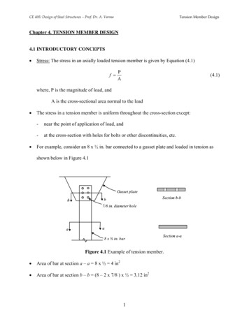
Iron vs Steel Bronze was an Alloy of Cu– Arsenic or Tin most common alloying impurity Steel is an Alloy of Iron– Carbon is the most common alloying impurity Iron and Carbon is probably the most usefulcombination in the history of Society Terms you should know– Forging – beating or hammering a material into shape– Casting – Pouring a liquid into a mold
Forms Low Carbon 0-0.2%– Wrought Iron– Pure, Ductile, typically about as strong as Bronze– High melting point ( 1500 C) Medium Carbon 0.2-2.1%– Steel– Very strong, hard, forgable,– 1000X harder than pure Fe– High melting point ( 1400 C) High Carbon 2.3-4.3%– Cast Iron or Pig Iron– Low Melting Point, Brittle, Not Forgable– Can only be Cast
Wrought IronThe Iron-Iron Carbide Phase DiagramSteelCast YaJ.png
Why is Steel Strong?SteelTwo Important phases of iron - Ferrite (BCC) - Austenite (FCC)How much carbon can you dissolvein the Iron?Ferrite very little ( 0.02%)Austenite Lots (up to 2.1%)AusteniteWhy is that important?When you heat Steel to 1000 Cwhat phase do you have?Austenite with lotsof CarbonWhen you cool it what does thecarbon do?It can precipitate intoCarbide particles. Strains crystalmakes dislocation motion difficult(hardens)Ferrite
Forms of iron Wrought Iron– Very little carbon ( 0.2%)– Difficult to slow the dislocations since carbon is dissolved– Soft, malleable, easily wroughtSteel– Medium carbon (0.2-2.3%)– Can dissolve carbon in Austenite but it wants to precipitate upon cooling– Properties depend on how fast you cool– Strain from Carbides greatly strengthens the steel– Must control both the amount of carbon and the temperingCast Iron– High Carbon (2.3-4.3%)– Forms lots of carbide phase– Make the material brittle (too much of a good thing)
Why is the Heat treatment important? For Steel if you heat it to 1000 C make Austenite– Slow Cool If you cool slowing make a mixture of Alpha iron and carbideparticles Give it time for the Carbon to form particles Natural Composite Slightly stronger than Bronze– Fast Cool or Quench Not enough time to transform to Alpha Iron Form Martensite (very hard phase of iron and carbon) Excess Carbon strains martensite (brittle)– Tempering Heat again to move carbon around and restore ductility
SohowdoyoumakeIron?Start with– Iron Oxide (either Fe2O3 or Fe3O4),– Limestone (CaCO3, Oyster Shells) and– Carbon (Charcoal) Layer these and light on fire and use bellows to get hot2C O2 2COFe2O3 3CO 2 Fe 3CO2 (makes Iron)Now have to get rid of sand from iron oxideCaCO3 CaO CO2 (make lime)CaO SiO2 CaSiO3 (glass slag)Get a mixture called a Bloom
EarlyWroughtIron:BloomeriesBloom Iron– Make a Bloom by heating the mixture we justdescribed– Beat on the bloom with a hammer to separate the ironfrom the slag– Left with pure wrought (low carbon) iron How do you add carbon to make steel?– Melting point too high until 1700’s– Heat Iron in Carbon rich air – Carborization– Carbon diffuses into the iron making outer layer ofsteel– Skilled craftsmen
Cast Iron Making (Blast Furnace) Method––––Same ingredients (Iron Ore, Charcoal and Limestone)Heat hotter and collect liquid iron from bottomCast Iron is also called Pig IronChinese skipped Bloomery stage and just made castiron from ancient blast furnaces– Not seen in Europe until 1500’s Now you have too much carbon– Use Finery Forge to remelt pig iron,– oxidize carbon and silicon– Make bloom and beat it, create wrought (bar) iron
Blast FurnaceEarly Blast Furnace
History of Iron and Steel 3500BC Beads in Ancient Egypt for iron– From Meteor (nickel content) First Iron Production 3000BC Syria and Mesopotamia Hittites mass produced Iron 1500-1200BC– Bloom Iron in small batch process– Use water power to beat blooms China starts Iron age later around 700BC– Used the first blast furnaces to make cast iron– Also used Finery forges to make wrought iron 300BC
HistoryContinuedBy 1400’s needs increased– Church bells, cannons etc– Blast furnace developed (Cast Iron) By 1500’s Japan is making the strongest Steel inthe world––––––Samuri Sword take a week just make the ironUse Magnetite (black sand Fe2O3) and charcoalBroad range of carbon, separate it by feel and soundMake the center from low carbon ductile steelThen add high carbon hard/brittle steel to outsideCreate a composite and the best steel for severalhundred years
History Continued– 1588 Queen Elizabeth limits use of Timber – By 1700’s have a timber famine (charcoal)Why not use Coal?– Too much Sulfur weakens steel– Coke the coal, Drives off impurities (thanks to beer)1709 Darby England– Low sulfur coke– Cast iron become cheap– Start of Industrial revolution Over 200 years income increases 10X Population increases 6X Machine based economy Free market, rule of law, no trade barriers
History continued Puddling– Invented in 1784– Stir Molten Pig (Cast) iron in oxidizing atmosphere– Observe it “come to nature”– Gather in a puddling ball Replaced by the Bessemer Furnace 1855– Blow Air through the melt– Rapidly remove carbon and silicon– Initially didn’t work tough to remove just the right amount– Instead decided to remove it all and add carbon back– Steel very fast (in 20 minutes) and efficient Today we use 1950’s Process– Basic Oxygen Process (BOP)– Inject pure Oxygen
AIMS OF STRUCURAL ENGINEER Structural design is a scientific & creative process. The structural design should satisfy Safety Stability Serviceability DurabilityAnd result in Economic (cost of construction & maintenance), Aesthetically pleasing, and Environment friendly structures.18
STEPS INVOLVED IN THE DESIGNPROCESS Estimation of probable loads, based on the planand elevation from the architect and the soilreport from the geotechnical engineer Arrival of the structural system Structural analysis(with the aid of computers) Design of various elements based on codalprovisions Estimation of quantities and cost of construction19
STEPS INVOLVED IN THE DESIGNPROCESS (cont.) Preparation of fabrication and erectiondrawings and bill of quantity of materials(BOQ)-should be approved by SE Construction by the contractor based on thespecifications. Inspection by SE for Quality Control atregular intervals As built drawing Maintenance till intended life.20
Iterative Design Process21
STRUCTURAL SYSTEMSClassification of structural systems Single-storey, single/multi-bay Multistorey, single or multi-bay Space structures: single, double or multilayer grids, steel frame folded plates,braced barrel vaults and domes Tension structures, tensegritic and cablesupported Stressed skin22
STRUCTURAL SYSTEMS(cont.)23
Types of Steel Framed Buildings Simple constructions24
Types of Steel Framed BuildingsBraced frames (a) vertical (b) on perimeter/interior wall and( c) around core25
Types of Steel Framed Buildings Continuous or Rigid Connections26
Rigid frames27
Types of Steel Framed Buildings Semi-Rigid Connections– They fall between the simple connections andrigid connections.– Most of the practical connections are semi rigidconnection only.– However in practice they are treated atsimple or rigid connections only!– Refer clause 4.2.1.2 or Appendix F of code formethods to deal with them.28
Steel Framed Buildings (cont.)Composite StructuresSteel frames with shear walls29
High Rise Structural Systems Several excellent systems have beeninvented in the past: Outrigger and belt truss Framed tube braced tube Tube in tube Bundled tube30
High Rise Structural Systems31
Outrigger and belt truss systemEx: 42 Story, 183 m tall First Wisconsin Center,Milwaukee, USA., Architect & Engineers: Skidmore,Owings & Merrill.32
Framed Tube & Tube in Tube SystemEx: World Trade Center, NY, 110 storey; Architect: M.Yamasaki,Engineer: L.E Robertson Associates33
Braced Tube SystemEx: 100 story John Hancock Center of Chicago, Illinois, Engineers:Skidmore, Owings and Merrill & Fazlur Khan34
Bundled Tube SystemEx: 108- Story, 442 m tall Willis (Sears)Tower has nine interconnectedbundled tubes; Architect: Skidmore, Owings and Merrill; StructuralEngineer: Fazlur Khan35
Structural IntegrityBS 5950, 2000 , Cl 5.1.2of IS 800:2007Minimum tie strength :Internal ties :0.5 WfStLaExternal ties:0.25 WfStLa Wf is the total factoredload / unit area, St is the tie spacing, La is the distancebetween columns in thedirection of tiesColumns should be tied in all directions to achievestructural integrity36
STRUCTURAL ANALYSIS Analysis : Determination of the axial forces,bending moments, shears & torsionalmoments– Slope deflection method– Moment distribution method– Portal method– Cantilever method– Matrix methods (stiffness & Flexibility)37
Software for Structural Analysis SAP2000STAAD III & STAAD PROETABSMIDASGT-STRUDLSTRUDSYou should be aware of any assumptions usedand limitations of these programs38
Methods of Analysis Elastic (first-order) Analysis Plastic Analysis Advanced Analysis (second order elasticanalysis or frame instability analysis) Dynamic Analysis Normal Steel building are analyzed usingElastic analysis. Dynamic/Advanced analysis necessaryfor tall/slender buildings.39
CODES AND SPECIFICATIONS Codes –Bureau of Standards EBCS Ensure adequate structural safety Aid the designer in the design process. Ensure consistency among differentengineers Protect the structural engineer fromdisputes – but do not provide legalprotection. Specifications are specific to a project issued by Architect/Project Manager40
DESIGN PHILOSOPHIES Working Stress Method of design(WSM). Ultimate Strength Design (USD) orPlastic Design Limit States Design [in USA, Load andResistant Factor Design (LRFD)]41
Working Stress Method(WSM) The first attainment of yield stress ofsteel is taken to be the onset of failure. The limitations due to non-linearity(geometric as well as material) andbuckling are neglected. Permissible (allowable) stress YieldStress / Factor of Safety(F.S.) Working Stress Permissible StressF.S. 1.67 for tension members, beams and short columns; 1.92 for longcolumns42
Limit States Design Plastic design: a special case of limit statesdesign, wherein the limit state of strength isthe attainment of plastic moment strengthMP Limit state: a state of impeding failure,beyond which a structure ceases to performits intended function satisfactorily Strength & serviceability limit states43
Design for Ultimate Limit StateThe design should be such that the overlap of two curvesare small-Probability of failure is within acceptable range.44
Limit states considered by CodeRd Σγif QidRd - design strength computed using the reduced material strengths Ru/γm whereRu is the characteristic material strengthγif - Partial safety factors for LoadsQid - Characteristic Design loads45
Comparison of WSM & LSDWorking stress method Factor of safety foryield stress- Allowablestresses ‘fy’. Analysis done underworking loads. Yielding or bucklingnever occurs atworking loads Deformations areevaluated at workingloads.Limit State Method Partial material safetyfactors (γm) for yield andultimate stress. Analysis done underfactored load [Workingloads x partial safety factorfor loads (γf)] Post buckling and postyielding are considered whileestimating capacity. Deformations are evaluatedat working loads.46
Partial Safety factor-Material, mSource: EBCS - 347
Partial Safety factor-Loads, Source: EBCS - 348
Check for Stability We should consider– General stability– Stability against overturning– Sway stability.49
Stability against overturning Important for Tall buildings and Cantilevers Components aiding instability and resistinginstability identified and multiplied withappropriate partial safety factor. Resisting components multiplied by a partialsafety factor of 0.9 and added with designresistance The resistance effect destabilizing effect50
Sway stability All structures to be checked for a minimumnotional horizontal load (0.5% of the verticalload at each level).51
Serviceability Limit States Deflections are to be calculated for all thecombination of Working loads, and checkedfor the maximum values given in code. Vibration will have to be checked whenvibrating loads ( due to machinery, cranes,)or activities such as dancing, marching areinvolved. Change the natural frequency by somemeans to reduce vibration52
Limits for Deflection53
Case Study for VibrationLondon MillenniumBridge experiencedvibration when openedon June 2000.37 fluid viscous and 52Tuned Mass Damperswere added to controlthe vibration and thebridge opened again inFeb 2002.54
Durability details of different coating/paintingsystems for durable structures Blast cleaning the surface enhancesthe life of paints Avoid traps for dirt and moisture Use of weathering / stainless steel55
Details for Corrosion Prevention56
Case study of Golden Gate Bridge During 1965 thelead paint wasremoved and aninorganic zincrich paint systemapplied. The coatingsystem is inexcellentcondition, evenafter 44 years57
Case Study: Richard J. Daley Center,Chicago Built in 1965 - the firstbuilding to beconstructed with a typeof weathering steel,(Cor-Ten) Even after 40 years thebuilding and and thesculpture are in greatcondition!58 p
Bundled tube 30. High Rise Structural Systems 31. Outrigger and belt truss system 32 Ex: 42 Story, 183 m tall First Wisconsin Center, Milwaukee, USA., Architect & Engineers: Skidmore, Owings & Merrill. Framed Tube & Tube in Tube System 33 Ex: World Trade Center, NY, 110 storey; Architect: M. Yamasaki, Engineer: L.E Robertson Associates. Braced Tube System 34 Ex: 100 story John
