Transcription
Evaluation of impedance tube methods A two microphone in-situ method for roadsurfaces and the three microphone transferfunction method for porous materialsMasters Thesis in the Masters programme in Sound and VibrationMARTIN WOLKESSONDepartment of Civil and Environmental EngineeringDivision of Applied AcousticsVibroacoustics GroupCHALMERS UNIVERSITY OF TECHNOLOGYGöteborg, Sweden 2013MASTER’S THESIS 2012:164
MASTER’S THESIS 2012:164Evaluation of impedance tube methods A two microphone in-situ method for roadsurfaces and the three microphone transferfunction method for porous materialsMartin WolkessonDepartment of Civil and Environmental EngineeringDivision of Applied AcousticsVibroacoustics GroupCHALMERS UNIVERSITY OF TECHNOLOGYGöteborg, Sweden 2013
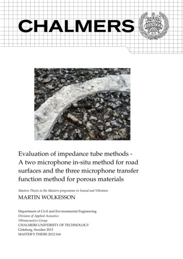
Evaluation of impedance tube methods - A two microphone in-situ method for roadsurfaces and the three microphone transfer function method for porous materials Martin Wolkesson, 2013Master’s Thesis 2012:164Department of Civil and Environmental EngineeringDivision of Applied AcousticsVibroacoustics GroupChalmers University of TechnologySE-41296 GöteborgSwedenTel. 46-(0)31 772 1000Cover:Picture of a piece of sealant applied to a road surface. This is to ensure that the joint tothe impedance tube fixture is air-tight.Reproservice / Department of Civil and Environmental EngineeringGöteborg, Sweden 2013
Evaluation of impedance tube methods - A two microphone in-situ method for roadsurfaces and the three microphone transfer function method for porous materialsMaster’s Thesis in the Master’s Programme in Sound and VibrationMARTIN WOLKESSONDepartment of Civil and Environmental EngineeringDivision of Applied AcousticsVibroacoustics GroupChalmers University of TechnologyAbstractThere are well-known methods to use an impedance tube with two microphones toobtain the acoustic characteristics of material samples. This setup can also be used tomeasure the absorption coefficient in-situ on road surfaces, as a non-destructive alternative to fit drilled out road samples into the tube. Moreover, impedance tubes canalso be used to obtain the non-acoustic parameters of a porous material using multiplemicrophones and transfer function calculations.In this thesis, the impedance tube measurement methods are investigated and developed to satisfy requirements in standards related to specifications of test tracks that areused for vehicle pass-by noise measurements. Measurements have been conducted toensure the conditions for low internal loss, to investigate sealant materials and to makecomparisons with related road surface measurements. An alternative transfer functionmethod has also been investigated using three microphones. Via semiphenomenological models one would be able to obtain acoustic and non-acoustic material parameters.The developed impedance tube measurement method can be considered as valid forin-situ measurement on road surfaces, in accordance with the current standards fornoise measurements on test tracks. In comparison to previous measurement results,the developed impedance tube showed reasonable results for the in-situ method. Theinitial three-microphone method did however not show measurement results that wereuseful to obtain additional acoustic and non-acoustic material results. Additional measurements of the transfer function over the sample material showed reasonable calculation results and narrowed down possible sources of errors.Keywords: Impedance tube, Kundt’s tube, absorption coefficient, absorption material,open porous asphalt, ISO 10844:2011, ISO 13472-2:2011i
ii
AcknowledgementsThis thesis work was carried out between January and June of 2012 at the Division ofApplied Acoustics in co-operation with the Noise and Vibration Laboratory at VolvoGroup Trucks Technology, AB Volvo, in Gothenburg.I would first of all thank my supervisor Ph.D. Anders Granlund at the Noise andVibration Laboratory, for the opportunity to write this thesis at AB Volvo, the interpretation of the measurement standards and the practical issues related to the impedancetube equipment.Moreover, I would like to thank my supervisor Ph.D. Patrik Andersson at Chalmers,for all the help with this thesis, especially for his knowledge to implement equationsinto functional features.Special thanks to all the staff at the Noise and Vibration Laboratory, in particularPh.D. Kaj Bodlund, Tech.Eng. Carl-Axel Carlsson, Dipl.Phys. Jona Hoffman, Ph.D.Jonas Klein, M.Sc. Erik Wennberg and M.Sc. Peter Zimmerman for always make timefor my questions about acoustic theory, measurement methods and feedback of thisthesis.iii
iv
ContentsAbstractiAcknowledgementsiiiContentsiv1. Introduction12. Impedance tube theory - Transfer function method using two microphones33. Impedance tube theory - Transfer function method using three microphones3.1. Acoustic characteristics . . . . . . . . . . . . . . . . . . . . . . . . . . . . .3.2. Non-acoustic characteristics . . . . . . . . . . . . . . . . . . . . . . . . . .3.2.1. The mixed displacement pressure formulation based on the Biottheory . . . . . . . . . . . . . . . . . . . . . . . . . . . . . . . . . .3.2.2. Solid phase equation in terms of solid phase displacement andthe pressure . . . . . . . . . . . . . . . . . . . . . . . . . . . . . . .3.2.3. Fluid phase equation in terms of solid phase displacement andthe pressure . . . . . . . . . . . . . . . . . . . . . . . . . . . . . . .3.2.4. Poroelasticity equation in terms of solid phase displacement andthe pressure . . . . . . . . . . . . . . . . . . . . . . . . . . . . . . .3.2.5. Rigid frame limitation model . . . . . . . . . . . . . . . . . . . . .3.2.6. Limp frame limitation model . . . . . . . . . . . . . . . . . . . . .3.2.7. Comparison of the rigid and limp frame limitation models . . . .3.2.8. Semiphenomenological models to relate to non-acoustic parameters3.2.9. The Delany-Bazley empirical model . . . . . . . . . . . . . . . . .4. Absorption material parameters4.1. Production of material samples4.2. Static flow resistivity . . . . . .4.3. Porosity . . . . . . . . . . . . . .4.4. Tortuosity . . . . . . . . . . . .5. Measurement related to ISO standard test tracks.7710111213141415151617191919202123v
5.1. Introduction . . . . . . . . . . . . . . . . . . . . . . . . . . . . . . . . . . .5.2. Comparison of ISO 10844:1994 and ISO 10844:2011 . . . . . . . . . . . . .5.3. Impedance tube measurement method in-situ according to ISO 134722:2011 . . . . . . . . . . . . . . . . . . . . . . . . . . . . . . . . . . . . . . .5.4. Residual void content . . . . . . . . . . . . . . . . . . . . . . . . . . . . . .5.5. Mean texture depth, MTD . . . . . . . . . . . . . . . . . . . . . . . . . . .5.6. Mean profile depth, MPD . . . . . . . . . . . . . . . . . . . . . . . . . . .5.7. Expected pass-by Noise level Difference from Texture level variation ofroad surface . . . . . . . . . . . . . . . . . . . . . . . . . . . . . . . . . . .232425272930306. Validation of the method by in-situ measurements6.1. Reference measurement to validate the impedance tube . . . . . . . . . .6.2. In-situ measurement on ISO 10844:1994 specified test track . . . . . . . .6.3. In-situ measurement to relate the absorption with the texture depth . . .333334367. Validation of the three-microphone method7.1. Two-microphone vs. three-microphone measurement method . . . . . .7.2. Additional acoustic parameters using the three-microphone measurement method . . . . . . . . . . . . . . . . . . . . . . . . . . . . . . . . . . .39398. Conclusion43Bibliography47A. Two-microphone method measurement results49B. Three-microphone method measurement results65vi40
1. IntroductionThe aim of this thesis has been to investigate the possibilities to measure the sound absorption of a test track using a developed impedance tube according to recently revisedstandards. A secondary aim was to investigate what other possibilities there are to obtain other characteristics of absorption materials by using this impedance tube. Thisthesis was done in collaboration with the Noise and Vibration Laboratory at AB Volvoin Gothenburg, which has supplied equipment, test samples and know-how.The theory behind the use of two microphones in an impedance tube will be presented in Chapter 2. The concept of impedance tube measurement can be described asmeasuring the reflection from an incident sound wave generated by a loudspeaker in atube. The sample under test will alter this reflection depending on the impedance at thesurface of the test sample. This setup will cause a standing wave that can be measuredby the microphones in the tube to be able to calculate the normal incidence absorptioncoefficient, since a part of the energy in the incident sound will be absorbed and dissipated to heat within the material. This kind of measurement method is well-knownand standardized methods can be applied. Furthermore, a well built impedance tubecan be seen as a specifically controlled test environment at a low cost. The test material samples used are also rather cheap to produce and the amount of cut-out materialis small compared to other measurement methods. Assuming some additional limitations, one can use three microphones and apply the theory described in Chapter 3,to obtain additional non-acoustic parameters derived from Biot’s theory of poroelasticity. The described material parameters are presented in more detail in Chapter 4 alongwith separate measurement methods. The measurement results presented in this thesiswere obtained using a measurement instruction [36] containing calculations accordingto these theory chapters.There are regulations which specifies the noise limit for vehicles sold in the EU, measured according to methods where the vehicle is driven on a test track. This test track isconstructed to ensure that the noise propagation is not dependent on the test track itself,which is achieved by an asphalt surface causing low sound absorption. The additionalrequirements for an impedance tube measurement method to measure in-situ on roadsurfaces are described in Chapter 5. Measurements were conducted, and presented inChapter 6 and 7, to evaluate the developed impedance tube against the standardizedrequirements of the respective methods, followed by the summarized conclusions inChapter 8.1
1. IntroductionCHALMERS, Master’s Thesis 2012:1642
2. Impedance tube theory - Transferfunction method using two microphonesSound radiation in an impedance tube can be described as a plane wave traveling in aduct. This is true, if one assumes that the wave length of the highest frequency is longerthan the lateral tube diameter, since modes will fit the cross-section of the tube causingunwanted non-plane wave modes. For this reason, the standard ISO 10534-2:1998 [2]sets the upper frequency limit for a circular impedance tube toc0(2.1)dwhere c0 is the speed of sound in air and d is the inner diameter of the tube.The upper frequency is also limited by the distance between the measurement pointsalong the tube, since one must ensure a certain phase difference of at least half a wavelength,c0f u 0.45(2.2)swhere s is the distance in between the microphone positions, often denoted as microphone spacing.The lowest available frequency is limited to the wavelength that are so long that thepressure at the microphones are very similar and no clear pressure difference can bemeasured,f u 0.58c0(2.3)sWith these set demands on the impedance tube, the complex sound pressure propagating in the incident and reflected direction can then be described asf l 0.05p I p̂ I e( jk0 x ϕ I ) e jωt(2.4)p R p̂ R e( jk0 x ϕR ) e jωt(2.5)where p̂ I and p̂ R are the magnitudes of the incident and reflecting waves respectively,ϕ I and ϕ R are the phase shift of the incident and reflecting waves respectively, k0 is thereal wave number in air and x is a position in the tube from the front surface of thesample. Hereafter are the phase and time notation included in amplitude p̂ I and p̂ R .3
2. Impedance tube theory - Transfer function method using two microphonesMic 1 Mic 2Rigid endSpeakerpISamplepRx1x2Ld0xFigure 2.1.: A sketch of an impedance tube configuration for two microphones, describing the incident and reflected wave and the positions of the microphones,speaker and sample.The complex sound pressure at the position of the microphones, see Figure 2.1, canthen be calculated asp1 p I ( x1 ) p R ( x1 ) p̂ I e jkx1 p̂ R e jk0 x1(2.6)p2 p I ( x2 ) p R ( x2 ) p̂ I e jkx2 p̂ R e jk0 x2(2.7)where x1 and x2 is the distance from the reference point, denoted 0 in the mentionedfigure, to microphone position 1 and 2 respectively.In order to correct for internal amplitude and phase mismatch between the microphones, one can use the microphone interchange method, also known as the microphone switching technique. This means that measurement is also conducted with thetwo microphones in a switched position, to obtain the transfer function between the microphones. This method opens up the opportunity to use low-cost and non-matchingequipment, since the use of the transfer function will reduce minor irregularities between the microphones.In this thesis the general form of a true transfer function is defined as in Equation2.8. However, all the transfer functions are in practice the estimates, Ĥ, of multiplesingle-sided auto-spectrum’s, AG, averaged over N iterations, see Equation 2.9.Hij Ĥij p j pi pj pipi pi AGij AGiiCHALMERS, Master’s Thesis 2012:1641N1N p j pi pi pi (2.8)(2.9)4
Moreover, the transfer function of the incident and reflecting waves between the microphone positions are defined asHI p I ( x2 )p̂ e jk0 x2 I jk x e jk0 sp I ( x1 )p̂ I e 0 1(2.10)HR p R ( x2 )p̂ e jk0 x2 R jk x e jk0 sp R ( x1 )p̂ R e 0 1(2.11)where s x2 x1 is the distance between the microphone positions, see Fig
For this reason, the standard ISO 10534-2:1998 [2] sets the upper frequency limit for a circular impedance tube to fu 0.58 c 0 d (2.1) where c 0 is the speed of sound in air and d is the inner diameter of the tube. The upper frequency is also limited by the distance between the measurement points along the tube, since one must ensure a certain phase difference of at least half a wave- length .
