Transcription
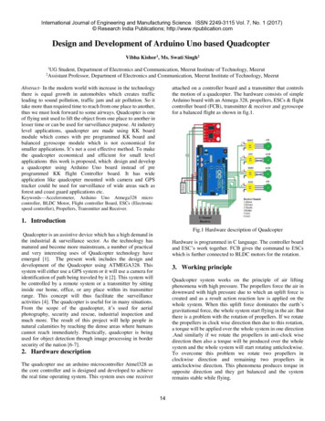
International Journal of Engineering and Manufacturing Science. ISSN 2249-3115 Vol. 7, No. 1 (2017) Research India Publications; http://www.ripublication.comDesign and Development of Arduino Uno based QuadcopterVibha Kishor1, Ms. Swati Singh212UG Student, Department of Electronics and Communication, Meerut Institute of Technology, MeerutAssistant Professor, Department of Electronics and Communication, Meerut Institute of Technology, MeerutAbstract- In the modern world with increase in the technologythere is equal growth in automobiles which creates trafficleading to sound pollution, traffic jam and air pollution. So ittake more than required time to reach from one place to another,thus we must look forward to some airways. Quadcopter is oneof flying unit used to lift the object from one place to another inlesser time or can be used for surveillance purpose. At industrylevel applications, quadcopter are made using KK boardmodule which comes with pre programmed KK board andbalanced gyroscope module which is not economical forsmaller applications. It’s not a cost effective method. To makethe quadcopter economical and efficient for small levelapplications this work is proposed, which design and developa quadcopter using Arduino Uno board instead of preprogrammed KK flight Controller board. It has wideapplication like quadcopter mounted with camera and GPStracker could be used for surveillance of wide areas such asforest and coast guard applications etc.attached on a controller board and a transmitter that controlsthe motion of a quadcopter. The hardware consists of simpleArduino board with an Atmega 328, propellers, ESCs & flightcontroller board (FCB), transmitter & receiver and gyroscopefor a balanced flight as shown in fig.1.Keywords—Accelerometer, Arduino Uno Atmega328 microcontroller, BLDC Motor, Flight controller Board, ESCs (Electronicspeed controller), Propellers, Transmitter and Receiver.1. IntroductionFig.1 Hardware description of QuadcopterQuadcopter is an assistive device which has a high demand inthe industrial & surveillance sector. As the technology hasmatured and become more mainstream, a number of practicaland very interesting uses of Quadcopter technology haveemerged [1]. The present work includes the design anddevelopment of the Quadcopter using ATMEGA328. Thissystem will either use a GPS system or it will use a camera foridentification of path being traveled by it [2]. This system willbe controlled by a remote system or a transmitter by sittinginside our home, office, or any place within its transmitterrange. This concept will thus facilitate the surveillanceactivities [4]. The quadcopter is useful for in many situations.From the scope of the quadcopter, it’s used for aerialphotography, security and rescue, industrial inspection andmuch more. The result of this project will help people innatural calamities by reaching the dense areas where humanscannot reach immediately. Practically, quadcopter is beingused for object detection through image processing in bordersecurity of the nation [6-7].Hardware is programmed in C language. The controller boardand ESC’s work together. FCB gives the command to ESCswhich is further connected to BLDC motors for the rotation.3. Working principleQuadcopter system works on the principle of air liftingphenomena with high pressure. The propellers force the air indownward with high pressure due to which an uplift force iscreated and as a result action reaction law is applied on thewhole system. When this uplift force dominates the earth’sgravitational force, the whole system start flying in the air. Butthere is a problem with the rotation of propellers. If we rotatethe propellers in clock wise direction then due to this rotation,a torque will be applied over the whole system in one direction.And similarly if we rotate the propellers in anti-clock wisedirection then also a torque will be produced over the wholesystem and the whole system will start rotating anticlockwise.To overcome this problem we rotate two propellers inclockwise direction and remaining two propellers inanticlockwise direction. This phenomena produces torque inopposite direction and they get balanced and the systemremains stable while flying.2. Hardware descriptionThe quadcopter use an arduino microcontroller Atmel328 asthe core controller and is designed and developed to achievethe real time operating system. This system uses one receiver14
International Journal of Engineering and Manufacturing Science. ISSN 2249-3115 Vol. 7, No. 1 (2017) Research India Publications; http://www.ripublication.comTwo basic phenomena are used for movement of quadcopter,thrust and torque. Quadcopter uses its four propellers attachedto motors which creates thrust and help quadcopter to elevatehigh. Motion of quadcopter are defined based on the inputvalues (x, y, z, θ, ɸ, ψ) given to it. Out of four motor attachedwith propellers, two motors rotate in clockwise (CW) directionwhile other two in counter clockwise (CCW) direction. Motionof quadcopter is thus controlled mainly by three movements.These movements are classified as4.1 Hardware Components Used4.1.1Arduino UnoArduino Uno is an open source physical computing platformused for building digital devices and interactive objects thatcan sense and control objects in physical world. It’s a microcontroller, based on AT mega 328P which consist of 14 digitalinput/output pins (out of which 6 pin are used as PWM output),6 analog inputs, a USB connector,16 MHz quartz crystal,power jack, an ICSP header and a reset button. Arduino boardconsist of everything needed to work with microcontroller.Arduino IDE (Integrated Development Environment) is use toupload programs to the arduino boards and further theseprogrammed boards can be used to perform intended tasks.3.1 Yaw Rotation (ψ)Yaw is defined as movement of quadcopter either to left orright and it is controlled by throttle stick of transmitter. Yawdecides the direction of quadcopter.3.2 Pitch Rotation (θ)Pitch is defined as the whole movement of quadcopter eitherin forward direction or in backward direction. It’s alsocontrolled by throttle of receiver. Moving the throttle inforward direction moves quadcopter in forward directionwhile moving throttle backward moves quadcopter inbackward direction [2].Fig.3 Flow chart for Quadcopter DesigningFig.2 Yaw, Pitch & Roll rotation3.3 Roll Rotation (ɸ)The movement about the longitudinal axis of quadcopter isknown as roll motion. Left or right motion of throttle stick isfollowed by quadcopter, it moves in towards right whenthrottle move to right and moves to left when throttle stickmoves in left direction. This parameter thus makes quadcopterto fly in left or right direction. [2].Fig.4 Arduino Development Board4. Design and MethodologyThe methodology adopted in designing arduino basedquadcopter is shown in fig.3.15
International Journal of Engineering and Manufacturing Science. ISSN 2249-3115 Vol. 7, No. 1 (2017) Research India Publications; http://www.ripublication.com4.1.2BLDC (Brushless DC Motors)4.1.4Also known as electronically commuted motors (i.e. ECMsmotors). BLDC motor are synchronous motor powered by DCelectricity. Rated in KV, where it rotates 1000rpm per 1 voltsupplied to it (if its rating is 1 KV). It offers several advantagesover brushed DC motors like more reliability, low noise,reduction in EM Interference (EMI), high torque per watt etc.Flight controller used in quadcopter is the main functioningbody of our aircraft. It’s a circuit board that that are equippedwith sensors which senses any change in orientation. It canreceive different commands sent by user to control speed ofmotors so that quadcopter could be stable in fly mode. Herewe have used arduino uno as our flight controller board. ESCsand Flight Controller board work together in following ways: ESCs receive command from micro controller circuitboard and further give command to the motors forrotation. FCB generates various commands for ESC andmotors according to the need of user.The whole system is controlled by this controller board.4.1.5Transmitter and ReceiverRadio transmitter uses radio signal to remotely controlquadcopter in wireless way, the commands given bytransmitter are received by a radio receiver connected to flightcontroller. The no of channels in transmitter determine howmany actions of aircraft can be controlled by pilot. Minimumof four channels are needed to control a quadcopter (whichincludes pitch. Roll, throttle, yaw).The stick control on radiostransmitter is known as gimbal. RC receiver used operates on2.4GHz of radio frequency (unless you do not have anyspecific need for a different frequency).Fig.5 BLDC Motor4.1.3Flight Controller BoardESC’s (Electronic speed controller)Four 30A ESCs (electronic speed controllers) are used inproposed Quadcopter. It convert the PWM signal receivedfrom flight controller or radio receiver and then drives thebrush less motor by providing required electrical power. ThusESC is an electric circuit that control the speed and directionof electric motor by varying the magnetic forces created by thewindings and magnets within the motor.Fig.7 Transmitter and Receiver4.1.6Li-Po BatteryLi-Po (Lithium Polymer battery) is a rechargeable battery oflithium ion technology. They provide higher specific energyand are being used where weight is a critical factor. It alsoprovide high voltage and long run time as they hold hugepower in small package and have high discharge rates requiredto meet the need of powering quadcopters.Fig.6 ESC’s (Electronic speed controller)16
International Journal of Engineering and Manufacturing Science. ISSN 2249-3115 Vol. 7, No. 1 (2017) Research India Publications; http://www.ripublication.comFig.8 Li Po (Lithium Polymer) Battery4.1.7Fig.10 PropellersFrame4.1.9The F-450 quadcopter frame is used as it is best suited for thepropellers and payloads which has to be lifted alongquadcopter. Quadcopter requires a light as well as rigid frameto host a LIPO battery, 4 BLDC motors, 4 ESCs & acontroller.Arms are made up of 5/8 hollow square aluminumbars and uses common nuts and bolts to hold the frametogether.Quadcopter requires a flight stability sensors that stabilizesquadcopter during its flight mode. L3G4200DH gyroscope islow power sensor with a sensing element and an IC interface(able to provide the measured angular rate to users throughdigital interface 12C/SPI)Fig.9 Quadcopter four arm Frame4.1.8GyroscopeFig.11 GyroscopePropellers5. Software ImplementationUsed 10 x 4. CW and CCW 4 pieces of black propellers as perthe requirements. Size of propellers varies with its applicationslike smaller propellers (under 8 inch) are used for racing.While large sized propellers (over 8 inches) along with motorsare used for carrying some weighted object like camera.The micro controller ATMEGA328 is programmed using Clanguage with arduino IDE software. It’s a developmentenvironment that simply uses an user interface for adding andediting in the arduino coding language.These program areutilized in various calibration steps which includes17
International Journal of Engineering and Manufacturing Science. ISSN 2249-3115 Vol. 7, No. 1 (2017) Research India Publications; http://www.ripublication.com5.1 Set up CalibrationSet up calibration illustrates the interconnections of varioushardware components used in quadcopter. Firstly program isuploaded on arduino board using IDE Software and then somemotor arming routine is followed as illustrated in flow diagramshown in fig.12.5.2 ESC’s CalibrationESC calibration varies with the brand of ESCs used inquadcopter. The calibration of ESIC is done on priority basiswith the help of a radio system for each rotor andcorresponding ESC. It includes the following steps as follows: First upload the program on controller board, then turnON the transmitter and put the throttle stick to itsmaximum. Now connect the battery.The auto pilot’s red, blue andyellow LED will light up in cyclic pattern that indicatesESCs are ready for calibration mode. By keeping transmitter throttle stick high, disconnect andthen reconnect the battery. Regular no of beeps on transmitter indicates the batterycell count and additional two beeps specify thatmaximum throttle has been captured. Now set the transmitter throttle stick down to itsminimum position. ESCs should now emit a long tone that indicatesminimum throttle has been captured and calibration iscomplete. Fig. 13 shows that the values of roll, pitch & yaw on IDEsoftware. For a balanced flight these parameters ofgyroscope must be set to -0,-0 & 0 respectively.Fig.13 IDE serial monitor output while ESC’scalibrationFig.14 IDE serial monitor output for all sticks in centerposition5.3 Flight Calibration ModeFlight calibration mode is a field testing mode. Placequadcopter on flight mode and then test the quadcopter onfield. After tuning the gyro parameters on the test stand, webegan to test the quadcopter in free flight. These tests wereperformed outdoors in a large open area, while maintainingsafe distance from the quadcopter.We were confident after the single-axis tests that thequadcopter would be fairly stable in the roll and pitch axes, butit drifted significantly in the yaw direction. After stabilizingcontrol on the yaw axis with proportional control only, thequad drifted much less in yaw and became much morecontrollable. We increased the proportional control term in theyaw PID until the quad was fairly responsive to yaw controlinputs. We found that the quad made small, fast oscillations inthe roll and pitch axes in flight. To fix this, we reduces thevibration on quadcopter by balancing the propellers, weFig.12 Set Up/Initialization workflow18
International Journal of Engineering and Manufacturing Science. ISSN 2249-3115 Vol. 7, No. 1 (2017) Research India Publications; http://www.ripublication.comisolated the sensor board from the remaining vibration usingvibration absorbing mount. Now quadcopter flight mode wasmuch stable. 6. Motor Thrust Testing To test the motor thrust and determine its relationship to ESCcommand signal, one of the motors was mounted to a load cell.The load cell had a 5 kg maximum load, more than adequatefor the less than 1kg maximum that we expected from themotor. For each BLDC motor and the propellers of 10X4.5 wewere able to generate a thrust of 0.902kg when supplied with2000μs pulse. So, by using the four BLDC motors we cangenerate the maximum weight lifting capacity of4X0.902 3.608kg for the Quadcopter provided the batterymust be fully charged. Implementing a GPS module on kit for tracking & spybased applications.This design can employ Motor Driver of high rating orRelay driver can be used for its commercial applications.Can be used for real estate photography by employingcamera on it. Other applications includes inspection,surveillance and monitoring a wide area by cameraequipped quadcopter.Pesticides sprinklingBased on the weight lifting calculations we can use our singleeconomical Quadcopter to lift these different modulessatisfying the weight lifting criteria.References[1]Stafford, Jesse, "How a Quadcopter works Clay Allen".University of Alaska, Fairbanks. Retrieved 2015-01-20.[2] Sandeeep Khajure, Vaibhav Surwade, Vivek Badak,“Quadcopter Design and Fabrication,” InternationalAdvance Research Journal in Science, Engineering andTechnology (IARJSET), Vol. 3, Issue 2, February 2016.[3] Quadcopter Dynamics, Simulation, and Control, January26, 2010.[4] David Roberts, "Construction and Testing of aQuadcopter," California Polytechnic State University,San Luis Obispo, CA, 93407, June, 2013.[5] S. Bouabdallah, P. Murrieri, R. Siegwart, "Design andControl of an Indoor Micro Quadrotor", Robotics andAutomation 2004. Proceedings. ICRA ‘04. 2004 IEEEInternational Conference on, vol. 5, pp. 4393-4398,2004.[6] J. Engel, J. Sturm, D. Cremers, "Camera-basednavigation of a low-cost quadrocopter", IEEE/RSJInternational Conference on Intelligent Robots andSystems (IROS), pp. 2815-2821, Oct. 2012, ISBN 21530858.[7]. J. Valvano, "Embedded Microcomputer Systems: RealTime Interfacing", Brooks-Cole, 2000, ISBN0534366422.Fig.15 Final arduino based quadcopter design7. ConclusionOur research work yielded a successful development ofArduino Uno based Quadcopter at a cheaper and affordableamount. Quadcopter which can be easily made from shelfcomponents. It can be used as a low cost alternative to variousapplications which includes pesticide sprinkling, end to enddelivery within the transmitter’s RF range, surveillance indefense and other sensitive places like nation border, mappingthrough remote sensing, etc. with very high level of precision.7.1 Future Possible UpgradationOur team goals were to design, test, and build a quadcopter kit.There are various possible up-gradation in future based on itsapplication which includes: Adding a sonic sensor module to controller board for moreaccurate altitude determination.19
The result of this project will help people in natural calamities by reaching the dense areas where humans cannot reach immediately. Practically, quadcopter is being used for object detection through image processing in border security of the nation [6-7]. 2. Hardware description The quadcopter us