Transcription
Arduino Guide and Project bookArduino Guide and Project BookTyson PopynickProt3us1@gmail.com
TitleAbout the ArduinoThe Arduino is a development board based on the ATMegamicroprocessors. It is fairly powerful as far as processorsgo, and suits most hobby purposes.There are multiple versions of the Arduino, including theMicro, Uno, Mega, Teensy and Zero. There are also plentyof other variants out there but these are the main boardsfreely available.The Arduino is an open source project, which means manycompanies have free access to the layout andspecifications of the board, and are legally allowed toproduce their own versions for sale, with – or withoutmodifications. These clones are not illegal, and are freelyavailable for you to purchase and use with the genuine Arduino Integrated DevelopmentEnvironment. (IDE).In the projects that follow we will be using the Arduino UNO. We will be using an Iduino brandedUno However any brand and version will be fine to use.About the guideThis guide is written from a hobbyist perspective, aiming to deliver the reader with sample codeand a basic but functional understanding of how the Arduino works, and how to use it.The projects aim to be informative and interesting, and most importantly the code should be assimple as possible to follow, and easy to modify for your own projects!If you have any queries or comments please email the author (Tyson) at prot3us1@gmail.com. Iwill respond ASAP and do my best to help you with your problems.SafetyPersonal safety is not generally an issue while operating the Arduino from USB or battery. Beaware of the voltages you are working with and always stay within your own abilities. None ofthe projects that follow are dangerous, however if you decide to use separate power (forinstance, to drive motors) you should be aware that incorrectly wiring or running your projectwhile plugged into USB can potentially damage your USB ports. Always follow the instructionsand check your wiring before plugging your Arduino in. Also remember the Arduino will beginrunning code as soon as it is powered. So if you wish to start a new project it is always goodpractice to upload a blank sketch to the Arduino before wiring any new modules, to ensure theIO ports are not doing anything that will compromise your new project. Tyson Popynick 2016 for Aus Electronics Direct1
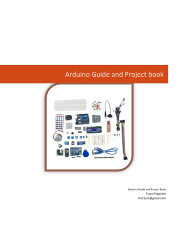
TitleWhat you needFor the projects in this guide we will make use of many commonly purchased modules andcomponents. I recommend purchasing one of the starter kits available fromwww.auselectronicsdirect.com.au to give your collection a boost, and set you up to make manyfun projects. I will try to explain choices on components as we go along so you can make yourown judgments on potential replacement parts, however if you are new to electronics it is bestto simply use exactly what is specified to ensure straightforward use.At minimum you will need: Arduino BoardIDE (Integrated Development Environment) Software(https://www.arduino.cc/en/Main/Software)A computer that will run the softwareA breadboardComponents or modules that you need for your desired project Tyson Popynick 2016 for Aus Electronics Direct2
TitleContentsAbout the product . 1Contents . 3Setup . 3Align the iron holder: . 3Prepare the sponge: . 3Insert the iron attachment: . 4Tin the tip: . 4Summary of setup: . 4Using the ZD-931 . 5 Tyson Popynick 2016 for Aus Electronics Direct3
TitleGetting StartedFirst download the Arduino IDE and install it. The latest version can be found atwww.arduino.cc/en/Main/Software.Once this is installed, plug your Arduino into a spare USB port on your computer and the driverswill be automatically installed.At this point your Arduino is running a blank sketch. A sketch is the Arduino term for a program.Every sketch consists of 2 main functions, and runs immediately once adequate power isprovided to the Arduino board.An example of a sketch will follow, and I will explain each part, the red text is NOT part of thesketch. The blue text IS://COPY FROM THIS LINE (You may include this line in the copy operation, but it is not necessaryto do so) - This line tells you to begin copying from here.//Global Variables go here - This is a single line comment.Global variables are like containers to hold data that the entire sketch can access.void setup() {/*Runs once at startup*/ - As mentioned, the code inside the startup() function will only run once,making it the perfect place to set up serial communications and other instructions that you need to run asingle time before the main loop starts.//You can also place LOCAL variables inside functions, only the function they are inside can access themhowever, and as soon as the function completes they are lost.}void loop() {/*Runs immediately after setup(), and once the end is reached, begins again at the start ofloop().*///This function is where your main code will go. It is run from top to bottom in the exact order it iswritten, and once the end is reached, it returns to the top and starts again. The Arduino will run this loopas fast as it possibly can. However it is free-running, so as you add more instructions it will run slower(slightly).//A quick word on local vs global variables – If I were to try to access a global variable from here, it wouldsucceed. I could edit or read it without a problem. However if I tried to access a variable that was declaredinside setup() it would fail, seeing as loop() is outside setup. This may seem confusing right now but youwill understand more as you progress.}//Additional FunctionsOnce you get into more advanced programming you will need to add your own functions, for instance –you may routinely flash an LED to indicate something. You could make a function here that would do so,then call this function from inside loop. This saves you having to repeat the same code over and overinside loop.//COPY TO THIS LINE (You may include this line in the copy operation, but it is not necessary todo so) - This indicates the end of a sketch. If you are copy/pasting you should stop copying at this line. Tyson Popynick 2016 for Aus Electronics Direct4
TitleDebugging and Error trackingIt is easy to get lost in code and create errors. If you forget a part of syntax such as a bracket orcomment, the IDE will likely tell you about the problem but if the code is written correctly, butdoesn’t function correctly – how do you find it?The Serial Monitor!This window allows us to have the Arduino send text back to the PC, so we can create a log ofwhat is happening, or even relay data back to ourselves as the Arduino processes live.The serial monitor is a 2 way connection, we can send and receive data to and from the Arduino.Of course most projects are not intended to be plugged into the PC forever so generallybuttons etc are a better method of interacting with the Arduino.Questions and troubleshootingPlease don’t hesitate to contact me at prot3us1@gmail.com with comments or questionsregarding the Arduino, I will do my best to reply promptly and sort any issues out. This service isoffered free of charge for troubleshooting and simple help. There is a service available where Ican assist you or take the lead on writing sketches for you for a modest fee. Feel free to enquireat the above email address if this sounds like something you require.Arduino ProgrammingArduino uses a proprietary coding language based on C# or MONO, the syntax should be familiarto anyone who has programmed in these languages before.Functions do not need to be declared, but variables do. Variables do not need to be explicitlyinitialized, although you should always do so to avoid problems later.Syntax:All lines of code should be appended with a colon to tell the compiler it is the end of aninstruction.All functions are called by name, followed by () with any parameters inside the brackets.All functions including if-else statements etc should be followed by curly braces to keep codeclean and minimize errors. For example: Tyson Popynick 2016 for Aus Electronics Direct5
TitleIf (x 1) {//instructions to execute if true}//Instructions to execute if false.Variables:Declare the type, then the name, then the value as follows variables are case sensitive so x is notthe same as X:Int temp 1;Bool x 0;String temp “Hello World”;Integers can be increased or decreased using the shorthand as follows:Int temp 0; //Declare a integer called temp, and initialize it to 0.temp ; //Adds 1 to temp. temp is now 1.temp--; //Subtracts 1 from temp. temp is now 0.Functions:Functions do not need to be declared like in some languages, instead you simply write thefunction itself and call it by name.To write the function you declare the type of data to be returned, or void if nothing is returned.You then declare the name, then any parameters that would need to be used also. An examplefollows:void flashLED(int numFlashes) { - void tells Arduino there is nothing returned. Int numFlashestells Arduino there should be an integer provided.for (int x 0; x numFlashes; x ) {digitalWrite(9, HIGH);delay(1000);digitalWrite(9, LOW);}Serial.write(“Flashed LED “);Serial.write(numFlashes);Serial.writeln(“ times.”);}To use this code we would do the following in the main loop or another function:flashLED(10); - Would flash the LED 10 times. Tyson Popynick 2016 for Aus Electronics Direct6
TitleAlternatively, if you need to return data, for instance if you are processing data, you would usethe following:Int addFive(int numberIn) { //We want to return an integer.numberIn 5; //take the number provided, and add 5.return numberIn; //return the answer.}This would be called in the same way, however it would return a value see the example thatfollows:Int number 7; //We have an integer with a value of 7 stored in the variable “number”.number addFive(number); //number equaled 7. The function then added 5 to it. So numbernow is equal to 12. Look at it as if the result replaces the function name, so this looks like:number Result of Function. And the result of 5 7 12.IO Ports:Accessing the IO ports is quite easy on the Arduino, they are referred to by their number.Arduino in most cases will automatically configure the pin between input and output based onthe function you use, however in some cases you may wish to manually set the pin up, forinstance if you need to set up the internal pull up or pull down resistors etc. If you have need ofthis you should go to www.arduino.cc, all of the available functions and variables are listedthere and this guide is simply meant to give the newcomer enough experience to get startedand understand enough about the device to then go on to their own research.LibrariesDuring your adventures with Arduino there are often premade programs used to interact withmodules and sensors. These are often top quality and there is no point to rewriting them. Theseare called libraries, they will allow you to use your modules quickly and easily.You can google search the libraries and find plenty of support and instructions on using them(above and beyond what I provide).A library allows you to call functions that are already written, for instance.the RFID librarycontains all of the raw code to access the hardware, all we need to do is initialize it and call thefunctions. If it wasn’t for this library we would need to manually code the protocol and datalines. A library does all the heavy lifting.The method of installing and using these libraries follows on the next page. Tyson Popynick 2016 for Aus Electronics Direct7
TitleFirst you should navigate to the Sketch - Include Library Menu.Click on Manage Libraries and the following window will appear: Tyson Popynick 2016 for Aus Electronics Direct8
TitleYou can then search by keyword for a library. In the example above I have searched for RFID as Iam looking for an RFID library.I am presented with 3 results. I choose the middle result and click the install button. If there is adrop down box with multiple versions, I choose the latest version. The reason I have chosen themiddle option is because the RFID module I have is based on the MFRC522 chip and uses SPIcommunication. You will be faced with similar options in the future and can always refer to thedocumentation from the manufacturer or place of purchase to help you choose the correctoption.This will now install the library to your Arduino directory. You have one final step to add it toyour project, and that is to select it from the list of libraries. You only need to install each libraryonce and then it is kept automatically in your Arduino directory for you to use any time. Tyson Popynick 2016 for Aus Electronics Direct9
TitleIn this example I have selected the MFRC522 Library we just installed. If you are installing adifferent library, please select the appropriately named option. Tyson Popynick 2016 for Aus Electronics Direct10
TitleProject 1(Serial Communication)Project Aim/Description:This project will show you how to communicate with the Arduino, including sending data to theArduino as well as getting data back from the Arduino.What you need: ArduinoExpected outcome:You will be able to send a string of text to the Arduino, as well as have the Arduino send a stringof text back.Procedure:This project is very simple, we will upload a sketch to the Arduino, open the serial monitor anduse the textbox to send a string to the board. The Arduino will then send the Text back, afterreformatting it.To begin, copy the code below into the IDE window (left) as illustrated in the image that follows,you will also want to bring up the SERIAL MONITOR (right in image). To do this, open the TOOLSmenu, and select SERIAL MONITOR. Tyson Popynick 2016 for Aus Electronics Direct11
TitleCODE://COPY FROM THIS LINEvoid setup() {Serial.begin(9600);Serial.println("Serial connection established.\n\nPlease enter text above and press send.\n");}void loop() {String temp Serial.readString(); /*This is a LOCAL variable, it will store any text we send TOthe Arduino FROM the PC.*/if (temp ! NULL) { //If the variable is NOT empty run the next instructionsSerial.print("You sent the string: "); //Print the stringSerial.print(temp); //then print the text we sent to the ArduinoSerial.println("."); //Finally print a fullstop. This is data FROM the Arduino TO the PC.}//If there is no text entered, the Arduino will continue processing from here But as there are nofurther instructions, it will return to the top and start again. If you were to put something heresuch as a Serial.print() command, it would fire constantly until you provide a string of text. Feelfree to try it!}//COPY TO THIS LINE Tyson Popynick 2016 for Aus Electronics Direct12
TitleWith the code copied into the IDE window (replacing all the text that was previously in there),you now simply need to click the UPLOAD button, and the Arduino will receive the code andstart executing it!The upload button can be found in the top left of the IDE window and looks like this:Press the button and you will see the progress at the bottom of the IDE window. Once itcompletes you will be greeted with the following text in the serial monitor:Serial connection established Please enter text above and press send.You will notice a text box at the top of the serial monitor window, with a send button next to it.Type some text into the box, and press enter or click the send button.You should now see:You sent the string: TEXT YOU ENTERED .Looking at the code we uploaded again, can you see what is happening?Notes:In this project we learned:How to enter and upload code to the Arduino.How to send and receive data to and from the Arduino.How to bring up and use the serial monitor.The Serial.print function will print text without adding a new line, so the text will continue on asif it was a single sentence.The Serial.println function does the same thing, except it adds a newline after the text, as if youhad pressed enter after typing a sentence. Tyson Popynick 2016 for Aus Electronics Direct13
TitleProject 2(PWM – Pulse-Width Modulation)Project Aim/Description:In this project we will look at Pulse-Width Modulation, how to use the Arduino to generate it,and what it does.What you need: ArduinoBreadboardLEDJumper Wires (Male to Male)1x 1k Resistor(Brown, Black, Black, Brown, Brown)Expected outcome:You will understand what PWM is, and how to use the Arduino to generate it. We will do this bydimming an LED. An LED is a Light Emitting Diode, and it can only be connected one way. If youconnect it in reverse, it will not work at all.You can distinguish the polarity of an LED in two ways. Firstly, there will be a longer leg and ashorter leg on the LED. The longer leg is positive and the shorter leg is negative. Sometimeshowever, the leg length may not be easily visible. For instance, if you have cut the legs shorter Tyson Popynick 2016 for Aus Electronics Direct14
Titlefor a different project, or bent them for a breadboard. In this case, you can use the secondmethod.The second method is to look at the plastic body of the LED. You will notice one side of it is FLAT.This signifies the NEGATIVE side of the LED.Procedure:In this project we will be wiring a circuit on the breadboard. A breadboard is a very handyprototyping board, which allows you to make non-permanent connections betweencomponents very fast, you can change components and connections without needing to bondanything together. Tyson Popynick 2016 for Aus Electronics Direct15
TitleA breadboard has internal connections that seem strange at first, but once you have used one afew times you should see the beauty of it.This is the inside of a breadboard, the dark lines are copper clips, the white area is insulating plastic.Notice how the edges of the board are connected in 2 separate lines, and the inside is connected in shortlines with a break down the middle. You can always refer back to this image to see what is going on insidethe breadboard later. It will seem confusing for now, but it will clear up once you have some experience.The edges are handy for running power, as they are accessible from anywhere on the board, and the innerlines are great for components. The gap in the middle is specifically designed to allow most microchippackages to fit across it, allowing access to each pin easily.In this project we will be connecting an LED to a pin on the Arduino. If we were to connect it tothe 5v output it would shine at full brightness. However we will be using the PWM abilities ofthe Arduino to “chop” the 5 volts up. Essentially we will turn 5v on and off rapidly, which willmake the LED turn on and off. The longer we allow the pulses to be, the brighter the LED willseem. The slower we make them, the dimmer it will seem.Please wire the circuit as indicated in the image below: Tyson Popynick 2016 for Aus Electronics Direct16
TitleOnce you have done this, please upload the following code:CODE://----Begin Code (copy from here)---//Variablesint pwmVal 255; //PWM range is 0 - 255. Change this value and reupload to see thedifference!void setup() {// put your setup code here, to run once:pinMode(ledPin, OUTPUT); //Set the pin we chose above as OUTPUT. This is actually automatichowever I included it to give an example of where you might use this feature.analogWrite(6, pwmVal); // the 6 is the pin on the Arduino the LED is connected to, pwmVal isthe variable containing the value for the PWM duration. analogWrite tells the Arduino this is aPWM pin.}void loop() {// put your main code here, to run repeatedly:}//----End Code (copy to here)----Notes:The BLUE text is code, the RED text is comments. As you can see there is very little coderequired for this project, however I am trying to give fairly detailed explanations in comments,which makes it look longer than it is. Tyson Popynick 2016 for Aus Electronics Direct17
TitleProject 3(Light Sensor Photoresistor/Light Dependent Resistor )Project Aim/Description:This project aims to show the reader how to use an LDR, also known as a photoresistor in theirprojects. The component itself varies its resistance based on the amount of light that hits thesurface, we can measure the resistance and use that to determine the level of light present.What you need: ArduinoBreadboardJumper Wires (Male to Male)Photoresistor1x 220 Ohm resistor(Brown, Black, Black, Red, Red)Expected outcome:The reader will be able to connect and read a photoresistor, and use the code in their futureprojects!Procedure:Wire the circuit as follows: Tyson Popynick 2016 for Aus Electronics Direct18
TitleCODE://----Begin Code (copy from here)---//Variablesint inPin A0; //Pin the sensor is connected toint sensorVal 0; //Variable to store sensor datavoid setup() {// put your setup code here, to run once:Serial.begin(9600);Serial.println("Serial Communication started.\n");}void loop() {// put your main code here, to run repeatedly:sensorVal analogRead(inPin); //analogRead will read the voltage on the pin specified andreturn it as a value between 0 and 1024.Serial.println(sensorVal); //Print the sensor reading to the serial window so we can view thedata.}//----End Code (copy to here)--- Tyson Popynick 2016 for Aus Electronics Direct19
TitleNotes:The LDR varies its resistance based on light hitting it, and the Arduino technically only readsvoltages, so how do we measure resistance?We are not REALLY measuring the resistance in this circuit, instead we are creating a resistordivider network between the LDR and the resistor, which will vary the voltage directly based onthe LDRs value. We then read the voltage out of the divider network and print that value.Google resistor divider network for more information. Tyson Popynick 2016 for Aus Electronics Direct20
TitleProject 4(Flame Sensor)Project Aim/Description:This project uses a Flame Sensor component to detect the intensity and presence of a flame.The sensor is designed to isolate and read specific bands of the IR and UV wavelengths todetermine if a pattern corresponding to a flame is present. It is quite an accurate reading, only areal flame should trigger it.What you need: ArduinoBreadboardJumper Wires (Male to Male)Flame Sensor1x 220 Ohm Resistor.(Brown, Black, Black, Red, Red)Expected outcome:The user will have the ability to read and use a flame sensor component in their projects, as wellas the code to view the data.Procedure: Tyson Popynick 2016 for Aus Electronics Direct21
TitleWire the circuit as follows (You may notice it is identical to the previous project, with only thesensor changed. It works in the same way resistance varies based on input):CODE://----Begin Code (copy from here)---//Variablesint inPin A0; //Pin the sensor is connected toint sensorVal 0; //Variable to store sensor datavoid setup() {// put your setup code here, to run once:Serial.begin(9600);Serial.println("Serial Communication started.\nReady to detect Flame.");}void loop() {// put your main code here, to run repeatedly:sensorVal analogRead(inPin); //analogRead will read the voltage on the pin specified andreturn it as a value between 0 and 1024. Tyson Popynick 2016 for Aus Electronics Direct22
Titleif (sensorVal 1000) {//FlameSerial.print("Flame: ");Serial.println(sensorVal);}else {//Uncomment the lines below to view the raw sensor data.//You can change the "if statement" above to reflect the difference in sensitivity and ambientvalues//Serial.print("Sensor Value: ");//Serial.println(sensorVal);}}//----End Code (copy to here)---Notes:Most of the 2 pin sensors use resistance as a form of reference, therefore they areinterchangeable without changing the code. I have added slightly more complex code for thisproject to try to help you start to see how code flows and functions. Tyson Popynick 2016 for Aus Electronics Direct23
TitleProject 5(IR Sensor / Remote)Project Aim/Description:What you need: ArduinoBreadboardJumper Wires (Male to Male)IR SensorRemote EmitterIRremote library (Type IR Remote into the library manager as described at the start of the guide) It is theIRremote library by sheriff.Expected outcome:The reader will be able to interface with, demodulate and read the signals from IR remotecontrols. Tyson Popynick 2016 for Aus Electronics Direct24
TitleProcedure:Wire the circuit as follows:CODE:Notes:This is a 3 pin sensor, and has no resistor! This sensor actually sends data in the form of pulsesto the Arduino, the IRremote library decodes these pulses and presents you with thisdemodulated data. Tyson Popynick 2016 for Aus Electronics Direct25
TitleProject 6(Tilt Switch)Project Aim/Description:This project shows the reader how to interface with a tilt switch sensor, it is the same methodused to interface with a button, as this sensor is essentially a button in the way that it works.What you need: ArduinoBreadboardJumper Wires (Male to Male)Tilt Switch Sensor1x 220 Ohm Resistor.(Brown, Black, Black, Red, Red)Expected outcome:The reader will know how to use a tilt switch in their future projects, as well as the code tointerface with it. Tyson Popynick 2016 for Aus Electronics Direct26
TitleProcedure:Wire the circuit as follows:CODE://----Begin Code (copy from here)---//Variables:void setup() {// put your setup code here, to run once:Serial.begin(9600);Serial.println("Serial Established.\nTilt board to continue.");pinMode (7, INPUT); //Set pin 7 to input for reading the sensor.}void loop() {// put your main code here, to run repeatedly:if (digitalRead(7) true){Serial.println("Tilted!"); Tyson Popynick 2016 for Aus Electronics Direct27
Title}else {Serial.println("Upright!");}}//----End Code (copy to here)----Notes:The tilt sensor is a ball bearing inside a tube, at one end there is a wire and there is a wirerunning along the entire length of the tube. When the ball rolls to the end with the wire present,the ball conducts electricity through both wires, completing the circuit When the ball is at the other end, there is no physical connection and the circuit breaks. Tyson Popynick 2016 for Aus Electronics Direct28
TitleProject 7(RGB LED)Project Aim/Description:The reader will be able to use an RGB LED to create many colors and effects in their projects. Wewill use PWM to control each of the channels in the LED (Red, Green and Blue). By mixing thesechannels we can achieve any color.What you need: ArduinoBreadboardJumper Wires (Male to Male)RGB LED ModuleExpected outcome:You will be able to use PWM to control an RGB LED and create any color you wish! This isextremely useful for many projects, from status indicators to mood lighting or color matchingwith sensors! Tyson Popynick 2016 for Aus Electronics Direct29
TitleProcedure:Wire the circuit as follows:CODE://----Begin Code (copy from here)---//Variables:int rPin 11;int gPin 10;int bPin 9; //Set the PWM pins to be used on the arduinoint rVal 0;int gVal 0;int bVal 0; //Set the values to 0 to begin withvoid setup() {// put your setup code here, to run once://No setup for this project.}void loop() {// put your main code here, to run repeatedly:analogWrite(rPin, rVal);analogWrite(bPin, bVal); Tyson Popynick 2016 for Aus Electronics Direct30
TitleanalogWrite(gPin, gVal); //Apply PWM output to each leg of the RGB LED, with the value storedin the corresponding variable.rVal random(0,255);gVal random(0,255);bVal random(0,255); //Randomise the variables to get a random color each timedelay(500); //Delay before changing colors, so we can see each change.}//----End Code (copy to here)----Notes:This code randomly changes the channels values so the light constantly changes color. You couldalso manually set the channels by changing the following code:rVal random(0, 255);gVal random(0, 255);bVal random(0, 255);to the following:rVal 0; //Change the 0 to the value you desire.gVal 0; //Change the 0 to the value you desire.bVal 0; //Change the 0 to the value you desire. Tyson Popynick 2016 for Aus Electronics Direct31
TitleProject 8(Read a potentiometer)Project Aim/Description:The reader will be able to read the value from a potentiometer and use them in their projects!What you need: ArduinoBreadboardJumper Wires (Male to Male)1x Potentiometer1x 220 Ohm Resistor(Brown, Black, Black, Red, Red)Expected outcome:The reader will be able to wire and use potentiometer values in their circuits. This is extremelyhandy to use as an input for brightness, volume, and even as a control input to move values in aselected range. I have seen projects use these as joysticks to control paddles in pong – typegames even! Tyson Popynick 2016 for Aus Electronics Direct32
TitleProcedure:Wire the circuit as follows: Tyson Popynick 2016 for Aus Electronics Direct33
TitleCODE://----Begin Code (copy from here)---//Variables:int varPin A0;int val 0;void setup() {// put your setup code here, to run once:Serial.begin(9600);Serial.println("Serial connection established.\nAdjust the Potentiometer to see the valuechange!");}void loop() {// put your main code here, to run repeatedly:Serial.print("Potentiometer Value: ");val analogRead(varPin);Serial.println(val);}//----End Code (copy to here)----Notes:This is sort of a manual LDR, the resistance changes based on the position of the potentiometerrather than the amount of light on the sensor, but t
About the Arduino The Arduino is a development board based on the ATMega microprocessors. It is fairly powerful as far as processors go, and suits most hobby purposes. There are multiple versions of the Arduino, including the Micro, Uno, Mega, Teensy and Zero. There are also plenty of other variants out there but these are the main boardsFile Size: 1MB