Transcription
Basic Electrical Engineering1 Experiment No 01 TITLE –WIRING EXERCISESOBJECTIVES:a) To study various wiring components (such as wires, fuses, plugs, sockets, lampholders etc.), their uses and ratings.b) To study the control of two lamps from two switches (looping in system)c) To study the staircase wiringd) To study the use of megger for insulation test and continuity test of wiringinstallations and machinesPREREQUISITE:1. Students should know alternating current and direct current supply2. Student should have basic knowledge about different types of conductors,resistance, different types of insulating materialsShree Ramchandra College of Engineering, Lonikand, Pune - 412 216.
Basic Electrical Engineering2Fig 1.1Fig 1.2Shree Ramchandra College of Engineering, Lonikand, Pune - 412 216.
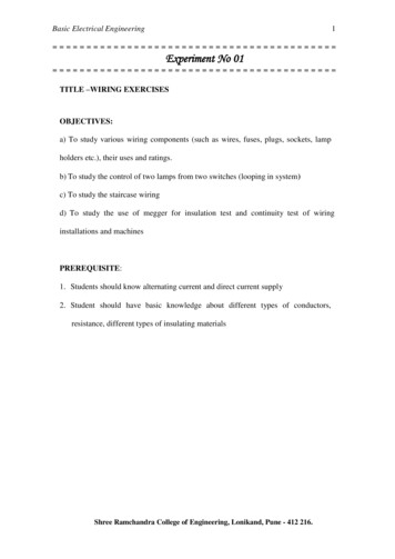
Basic Electrical Engineering3Experiment No 1ATITLE – STUDY OF WIRING COMPONENTSI. Types of WiresVarious types of wires are used for electrical wiring. The commonly used typesarea) V.I.R. (Vulcanized India Rubber) wires: these types of wires consist of a tinnedconductor coated with rubber insulation. The thickness of rubber varies with thevoltage for which the wire is designed i.e., 250 or 660 volts. This rubber insulationis not moisture or heatproof.b) C.T.S. (Cable Type Sheathed) wires: In this type, ordinary insulated conductorsare provided with an additional tough rubber sheath .This also provides aprotection against moisture, chemical fumes and tear.c) P.V.C (Poly vinyl chloride): These are the most commonly used wires. Thesehave conductors with P.V.C insulation. PVC is non- – hygroscopic. However,PVC softens at high temperature and hence is not used where extremes oftemperature occur e.g. in heating appliances.d) Cables: These consist of individually insulated conductors which are put togetherinside a protective mechanical covering. There are two types of cables used.i) Aerial cables.ii) Underground cables.The construction of cable is as follows- (Refer figure No.1.1)Conductor or Core: Each cable has one central core or a number of cores (2, 3, 3 1/2or 4) which are normally made up of tinned copper or aluminum conductor. Strandinggives flexibility to the cable.Insulation: Commonly used insulating materials are varnished cambric, vulcanizedbitumen or impregnated paper. Impregnated paper is invariably used for highervoltage cable.Metallic Sheath: Usually, a lead alloy or aluminum sheath is provided over theinsulation for providing mechanical protection and preventing entry of moisture in theinsulation, which impairs its insulation property.Bedding: The bedding consists of a layer of fibrous material like jute or sometime atape of strong coarse cloth of jute. It protects the metallic sheath against corrosion andfrom mechanical injury due to armouring.Armouring: This layer usually consists of one or two layers of galvanized steel wireor steel tape and is provided to protect the cable from mechanical injury while layingit during the course of its use.Serving: A layer of fibrous material like jute cloth is provided over the armouring toprotect it from atmospheric condition. This layer is known as serving.Shree Ramchandra College of Engineering, Lonikand, Pune - 412 216.
Basic Electrical Engineering4II Designation of Wiresa) Type of Conductors: Copper & aluminum conductors are commonly used. b)Type of Wires: Already discussed.c) Size of Wires: As current flows through the wire, heat proportional to the squareof the current is produced. This heat governs the current carrying capacity of theconductor, for a given size. (Refer figure 1.2)Instead of referring to the wire size in terms of cross – sectional areas, the gaugenumber designates them. The British standard wire gauge is commonly used inIndia. The smallest wire gauge is of No.40 having a diameter of0.1219 mm. The largest number of wire is 0,000,000 (named as seven zero) or writtenas 7/0, having a diameter of 127000mm. Thus, it will be observed that the higher thenumber of wire gauge, the smaller is the diameter.The wire used for ordinary house wiring purposes have single solid conductor,whereas, wire with higher capacity or flexible wire have stranded conductors forflexibility. Therefore the number of strands and their gauge number specify the size ofthe wire. For example, a wire of ‘1/18’ size will have a single solid conductor of 18SWG, whereas, a wire of ‘3/20’ size will have three stands of20SWG.d) Number of Cores: wire (cables) when used for some specific application may havesingle, 2, 3, 31/2 or 4 core.e) Voltage Grading: It is the voltage to which the insulation of wire can safelywithstand. Wires are normally graded for 250 V or 660 V.III. Various Systems of WiringSeveral systems of wiring are in use. However the choice of the particular type of wiringwill be decided by the following factors.a) Durability b)Safetyc) Appearance d)Accessibility e)Maintenance f) CostThe following systems of wiring are commonly used in actual practice.a) Wooden Casing & Capping Wiring: Casing is a rectangular strip made fromseasoned teakwood and usually has two or three grooves. It is fixed withcountersunk wood screws using rawl – plug or wooden plugs (gutties) on wall or ceiling.( Refer figure 1.3)Shree Ramchandra College of Engineering, Lonikand, Pune - 412 216.
Basic Electrical Engineering5Fig 1.3Porcelain round cleats are used to keep the casing away from the wall or ceiling in orderto protect it from dampness. The V.I.R or P.V.C wires are run in the grooves in a woodencasing. The casing is then finally covered at the top by a rectangular wooden strip of thesame width as that of the casing. This strip known as capping is then screwed to thecasing. The casing and capping are given a double coating of shellac varnish from insideand at the back. They are painted or varnished from the out side after erection.Application: This system is now almost superseded by other type of wiring even throughit was very popularly used for residential and commercial buildings in the early days.However it is still in use for special situations and in places to fit in with the internaldecoration of a room.Advantages:(a) Gives good mechanical protection to the conductors. (b)Neat appearance.(c) Installation and repairs are easy in comparison with conduit wiring.Disadvantages(a) The system is costly since it involves highly skilled labour.(b) Wood being inflammable, it is quit susceptible to fire hazards.(c) In spite of coating with varnish, it can not be used in damp situations.b)Conduits Wiring: In this system, V.I.R or P.V.C wiring is run through blackenameled or galvanized metallic tubing called conduits.Types of Conduits:i) Thin Wall Conduits: These are the light gauge iron conduits with a seam alongits length.ii) Rigid Conduits: These are the heavy gauge iron conduits either solid drawn orwith welded seam. These conduits being more costly are normally used for allmedium pressure (250 to 600 volts) circuits and in place where a good degree ofmechanical protection and absolute freedom from moisture is required.Shree Ramchandra College of Engineering, Lonikand, Pune - 412 216.
Basic Electrical Engineering6Type of Conduit Wiring: Depending upon whether the conduits are laid inside thewall or supported on the walls, there are two types of conduit wiring.i) Surface Conduit Wiring: In this method, conduits are fixed on the wall bymeans of saddles screwed to rawl – plugs or wooden plugs embedded in thewall. In damp situation, these conduits are spaced apart from the wall surfaceby small wooden blocks fixed below the pipe at regular intervals as illustratedFig 1.4ii) Concealed Conduit Wiring: This method employs heavy gauge rigidconduits buried under wall plaster. Such wiring is used in case where beauty isthe main consideration irrespective of cost.Application: Surface conduit wiring is mainly used for all indoor and outdoor wiringof permanent nature for light and power e.g. in godowns, workshops and publicbuildings. The concealed type is preferably used in public building, offices, shops andhouses for its nice appearance.Advantages:(a) Very long life.(b) Provides good protection against mechanical injury, moisture and fire – hazards.(c) Neat appearance. Particularly, the concealed type of conduit wiring adds to beautyof the building.(d) Less maintenance.Disadvantages:(a) Most costly system of wiring(b) Erection requires highly skilled labour and time.(c) Repairs, particularly with concealed wiring are difficult and take long time.(d) In the absence of earth continuity on all conduit joints, there is the possibility ofan electrical shock.(e) If proper precaution is not taken to file sharp edges of the conduits, there ispossibility of damage to the wire insulation.Shree Ramchandra College of Engineering, Lonikand, Pune - 412 216.
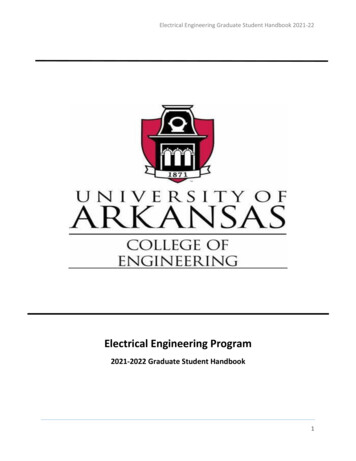
Basic Electrical Engineering7IV. Wiring Accessoriesa) Fuses :An electrical circuit must be safeguarded against the harmful effects of excessivecurrent. This excessive current may be because of overloading or short circuit faults.A high current leads to an excessive heat rise which, if adjacent to inflammablematerial will almost certainly cause an outbreak of fire. In all such cases, therefore itis necessary to interrupt these excessive currents before they cause any damage. Fuseis the simplest current interrupting device for the protection against excessive current.Function of the Fuse: In general, the fuse consists of a small piece of metalconnected in between two terminals mounted on the insulated base.When the fuse is inserted in a circuit to be protected, it carries the normal workingcurrent without heating. But when the current exceeds the pre determined value itmelts due to rapid overheating. The circuit is then interrupted preventing any damagedue to excessive current.Fuse Element Material: Metals like tin, zinc, silver, antimony, copper and aluminumcan be used for fuse elements. However, metals with low melting point like tin, lead,zinc or lead – tin alloys are found more suitable for this purpose. The main objectionfor the lead- tin alloys is that these alloys being soft are apt to spread under pressure.The most preferred lead – tin alloy for a fuse element contains 37% lead and 63% tin.Normally, lead – tin alloy wire is not used beyond 10 amperes because with highercurrents, a wire with a large diameter will be required and after fusing, the metalreleased will be excessive. Copper wire is most suitable for higher currents.The present trend, however, is to use silver for higher currents despite its higher costas it is comparatively free from oxidation.Types of Fuses: following two types of fuses are commonly used in practice.(i) Semi – Enclosed or Rewirable Type Fuse:Construction: In this type of fuse, the fuse element is semi – enclosed i.e. neitheropen nor totally closed. They are available in various forms. Figure 1.5 illustrates atypical rewirable fuse bridge and base (also known as a kit – Kat type fuse unit.)The fuse element (E) consists of a short length of fuse wire of diameterdepending upon the current rating of the circuit the fuse is protecting. The wire isthreaded through a small hole in the porcelain fuse bridge (B1) and secured to thecontacts (C) by means of screws (S). The incoming and outgoing live or phase wiresare connected permanently with the help of connecting terminals to the base (B2).These terminals of the base are bridged by the contacts of the bridge through the fuseelement when the bridge fits in to the base.Operation: The fuse is wired in series with the circuit to be protected. At the fuse,because of the highest resistance, more heat is developed than at any other point in thecircuit. During the fault, the circuit current rises in value. Therefore, the heatproduced at the fuse causes temperature of the fuse wire high enough to melt the wireand break the circuit.Shree Ramchandra College of Engineering, Lonikand, Pune - 412 216.
Basic Electrical EngineeringBasic Electrical Engineering8Page 7 of 20Shree Ramchandra College of Engineering, Lonikand, Pune - 412 216.
Basic Electrical Engineering9Fig 1.5Application: Commonly used in domestic installations and the other circuits wherevery low values of fault currents are to be handled.Advantages:(a) They are cheaper(b) After blowing off the fuse element, the bridge can be pulled out and again rewiredwith a new fuse wire. Thus, service can be restored very quickly with negligibleadditional expenditure.Disadvantages:(a) Cannot be used for higher values of fault current.(b) Protection is not reliable due to inaccurate characteristics.(c) Since the wire is exposed to air, it is subjected to deterioration due to oxidationcaused by heating. This decreases the effective diameter of the wire. Heating dueto increased resistance causes premature failure under normal load.(d) Slow speed i.e., current interruption is not quick in comparison with otherinterrupting devices.(e) Risk of fire – hazards due to external flash on blowing.ii) High Rupturing Capacity (H.R.C) Cartridge Fuses:With the increase in fault current level, the fuse clearing the fault would be calledupon to withstand extremely heavy stresses in the process. A rewirable fuse would notbe able to withstand these stresses and would probably disintegrate violently. Thetotally enclosed type – high rupturing capacity cartridge fuse, specially designed forextremely rapid operation are, therefore, used for such duties.Shree Ramchandra College of Engineering, Lonikand, Pune - 412 216.
Basic Electrical Engineering10Basic Electrical EngineeringPage 8 of 20Shree Ramchandra College of Engineering, Lonikand, Pune - 412 216.
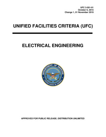
Basic Electrical Engineering11Fig 1.6Application: With the increasing loads and size of the network, H.R.C. cartridgefuses are now gradually replacing the rewirable types, particularly in industrialinstallations. They are also frequently used in low voltage distribution systems.Advantages:(a) Being totally closed, there is no deterioration of the fuse element(b) Due to accurate characteristics and consistent performance, protection is reliable.(c) High-speed operation.(d) Ability to clear high value of fault current.(e) Its operation is silent and without flame, gases or smokes. Hence safe from thepoint of view of fire hazards.Disadvantages:(a) Costly in comparison with rewirable type fuses.(b) The cartridge is to be replaced by a new one after each operation.Over heating of the adjacent contacts is possible during the operation of the fuse.b) Study of miniature circuit breaker (MCB)A MCB is a mechanical switching device which is capable of making, carrying andbreaking currents under normal circuit conditions and also making, carrying for aspecified time and automatically breaking currents under specified abnormal circuitconditions such as those of short circuit. In short, MCB is a device for overload andshort circuit protection. They are used in residential & commercial areas.Shree Ramchandra College of Engineering, Lonikand, Pune - 412 216.
Basic Electrical Engineering12Basic Electrical EngineeringPage 9 of 20Shree Ramchandra College of Engineering, Lonikand, Pune - 412 216.
Basic Electrical Engineering13Fig- MCBRating:In most cases, the ampere rating should not exceed the current-carrying capacity ofthe circuit. For example, if a conductor is rated at 10 amps, select a circuit breaker nolarger than 10 amps.Ampere ratings for miniature circuit breakers range from 10 to 150 amps. Voltageratings for miniature circuit breakers are 120/240-volt and 240-volt. Interruptingratings for miniature circuit breakers are 10, 22, 42, and 65 KAIC (thousand ampsinterrupting capacity).Advantages: Instant re-closing of the circuit after a fault has been cleared. Safety disconnect features for circuit isolation. Terminal insulation for operator safety. Ampere ratings that can be fixed and modified. It is reusable, hence very little maintenance and replacement costs. Lower power losses. Simplicity of mounting and wiring. Lower space requirements.Disadvantages: More expensive as compared to fuse. Difficult to identify where the fault occurred.Applications: MCBs find wide application in residential, commercial and industrialoperations.c) SwitchesA switch is a manually operated mechanical device used for making or breaking theelectrical circuit. Single pole switches are normally employed for controlling lightingand heating circuits in domestic wiring. Depending up on the circuit requirements,they may be of single–way (fig. 1.7a), two-way (fig. 1.7b), two-way center off (fig.Shree Ramchandra College of Engineering, Lonikand, Pune - 412 216.
Basic Electrical Engineering141.7c), intermediate (fig. 1.7d), or push-button (fig. 1.7e) types.Basic Electrical EngineeringPage 10 of 20Shree Ramchandra College of Engineering, Lonikand, Pune - 412 216.
Basic Electrical Engineering15Fig 1.7Fig 1.8These are generally made of hard plastic or bakelite and are fitted with quick makeand – break arrangement –using spring so as to reduce arcing time. This is essentialbecause the arcing between the switch blades and contact terminals burns or damagesthe switch contacts and thereby reduces the life of the switch. The switches, which aremounted on the mounting blocks directly, fixed over the surface of the wall, are calledsurface switches or tumbler switches. These switches project out of the surface of thewall. On the other hand, the switches that are fixed in flush with the wall are calledflush switches. Flush switches are normally used for better appearances.Two or three-pole switches combined with fuses (Refer figure 1.8) are normallyemployed as main switches in domestic wiring. Combination of switch and fuses isenclosed in the same iron casing. The switch is fitted with quick make –and-breakarrangement. For safety purposes, mechanical interlock is also provided whichprevents the case being opened when the switch is on, or the switch being closedwhen the case is open. Main switches are commonly available with the rating of 250V– 15A, 500V – 30A, etc.d) Lamp Holders:Lamp holders made up of brass, bakelite or hard plastic are used to hold thelamps and connect them to the wiring. Connection of lamps to the wiring through theholders facilitates their quick removal or replacement without disturbing the wiring.The lamp holders are basically either of bayonet type or screw type. Lamps withbayonet base (or cap) are pressed against spring loaded brass plungers and turned inbayonet type holders whereas lamps with screw based are screwed into the screw typeShree Ramchandra College of Engineering, Lonikand, Pune - 412 216.
Basic Electrical EngineeringBasic Electrical Engineering16Page 11 of 20Shree Ramchandra College of Engineering, Lonikand, Pune - 412 216.
Basic Electrical Engineering17holders. Each of the above two types of holder can be further subdivided into thefollowing commonly used types. (Refer figure 1.9)Fig 1.9i) Pendant Holders: These are for the lamps, which are to be, kept hanging from theceilingsii) Batten Holders: These holders can be screwed on the wooden blocks and as suchare suitable for the lamps, which are to be fixed on the walls or ceiling. Angle battenholders are also available for fix angle directional lighting.iii) Screwed Holders: This type of holders can be screwed on to a wall bracket oflong stand of a table lamp.e) Ceiling Roses:Connection to the pendant lamp holders, fluorescent tubes and ceiling fans areprovided from ceiling roses using flexible wires.The ceiling roses are made of bakelite and have either two or three terminalplates. Accordingly, they are called two – plate or three – plate ceiling roses. (Referfigure 1.10)(a) Two-Plate Type Ceiling Roses(b) Three- Plate Type Ceiling RosesFig 1.10f) Plug and Sockets:These are used for providing connections to portable appliances such asmixers, table lamps, etc. and are made of bakelite. Even though the plugs and socketsof both two pin type and three – pin type are available, from the point of view ofsafety, only three pin type with a provision for earth connection are now used. TheShree Ramchandra College of Engineering, Lonikand, Pune - 412 216.
Basic Electrical Engineering18terminal sleeve with thicker cross – section on the three – pin type socket is used forBasic Electrical EngineeringPage 12 of 20Shree Ramchandra College of Engineering, Lonikand, Pune - 412 216.
Basic Electrical Engineering19earth connection. Both three – pin type and two type plugs and sockets are availablewith the rating of 5A – 250V and 15A – 250V. (Refer figure 1.11)(a) Two-Pin Plug Socket(b) Three-Pin Plug SocketFig 1.11V. Domestic InstallationsThe power to the domestic wiring installation is tapped from the low voltagedistribution line known as the distributor. The wires supplying power from thedistributors to the domestic wiring installation are known as service mains. Fig. 1.12shows the layout of a domestic installation for a small house.The supply is a single – phase a.c. and brought in through the supplycompany’s sealed fuse box and meter to the consumer’s main switch. From the mainswitch, supply is given to the distribution box, which feeds the various sub–circuits.Two separate meters can be provided, one for lighting (with 5 amperes capacity) andthe other for power (with 15 amperes capacity). For the sub – circuit supplyinglighting load, the number of points connected (i.e., lamps, tubes, and fans. etc.) shouldnot exceed 10 and the total load should not be more than 800W. For the sub-circuitsupplying power to the appliances such as heaters, electric irons, single phase motors,etc. the numbers of points connected in one sub – circuit should not exceed two andthe total load should not be more than 3000 watts.Shree Ramchandra College of Engineering, Lonikand, Pune - 412 216.
Basic Electrical Engineering20Basic Electrical EngineeringPage 13 of 20Shree Ramchandra College of Engineering, Lonikand, Pune - 412 216.
Basic Electrical Engineering21Fig 1.12Shree Ramchandra College of Engineering, Lonikand, Pune - 412 216.
Basic Electrical EngineeringBasic Electrical Engineering22Page 14 of 20Shree Ramchandra College of Engineering, Lonikand, Pune - 412 216.
Basic Electrical Engineering23Experiment No 1BTITLE – STUDY OF WIRING(a) Aim: Control of One Lamp By Means of One Single Pole Switch.Apparatus: Switches, lamps, wires, & fuse.Fig 1.13Wiring diagram: for controlling the lamp L, a single pole switch A is introduced inits circuits as shown in fig. 1.13The live or phase wire is always connected to the lamp holder through the switch,whereas, neutral is connected directly to it. All the accessories such as a single poleswitch, lamp holder, etc. are always fitted on the teak wood round block.Working: When the switch is turned on, a full supply voltage is applied across thelamp terminals and the lamp glows. Thus, the lamp can be independently controlledby the single pole switch.Application: the circuit is used for single room wiring.(b) Aim: Two or More Lamps with Individual On-Off Control.Wiring diagram: Fig.1.14 Shows the necessary wiring diagram using loopingin system. Instead of running separate wires for each lamp from the supply point, theyare looped in from one lamp to the other in manner shown in fig.1.14.Working: In this case, it will be observed that the position of any switch does notaffect the working of other lamps and thus, each lamp is controlled independently byits own switch.Shree Ramchandra College of Engineering, Lonikand, Pune - 412 216.
Basic Electrical Engineering24Basic Electrical EngineeringPage 15 of 20Shree Ramchandra College of Engineering, Lonikand, Pune - 412 216.
Basic Electrical Engineering25Fig 1.14Application: This system is commonly used in domestic wiring as it saves length ofwire and other wiring (c) Aim: Control of One Lamp by Means of Two Switches. (Stair CaseWiring)Wiring diagram: Fig. 1.15 shows the wiring diagram. To control the lamp L fromtwo places using two ways switches, A & B in the respective positions. As usual,neutral is directly connected to one terminal of the lamp holder and the phase wire isconnected to its other terminal through two way switches A & B.Working: With two way switches A & B in the positions shown, the lamp L will bein the ‘off’ condition. The lamp can be again switched on by one of the two switches& can be switched off by the other by changing their blade positions i.e. the lamp,switched on by the switch. A can be switched off by the switch B and vice versa.Thus, one single lamp can be controlled from two places.Shree Ramchandra College of Engineering, Lonikand, Pune - 412 216.
Basic Electrical Engineering26Fig 1.15Basic Electrical EngineeringPage 16 of 20Shree Ramchandra College of Engineering, Lonikand, Pune - 412 216.
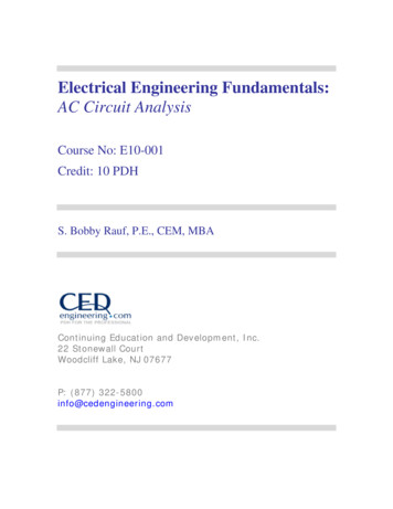
Basic Electrical Engineering27Application: It is normally used for staircase & corridor lighting.A1122B1212LONOFFOFFONExperiment No 1CTITLE: STUDY OF MEGGERThe insulation testing instrument megger is based upon the principle of ohmmeter.Construction: - Figure 1.16 shows the constructional diagram of a megger. It consistsof two primary elements, a direct reading ohm-meter and a small hand driven(through gearing) permanent magnet type D.C. generator G which supplies the testingvoltage such as 500, 1000 or 2500V depending upon the instrument. The movingsystem of the ohmmeter consists primarily of two coils C1 and C2. These coils aremounted rigidly at an angle to one another and move in the air gap of a permanentmagnet. Coil C1, called the current coil or deflecting coil is connected between thenegative brush of the generator and the line terminal along with the resistance R1 inseries with it. Coil C2, called the potential coil or control coil, is in series with theresistance R2 and connected across the supply of the generator. This coil is narrowerthan coil C1 and encircles a part of the C- shaped iron core D during the course of itsmovement. Thin flexible ligaments exerting negligible tension on the moving systemmake connections to the coil. The whole moving system is supported between the twojewel bearings. The insulating bushing of the line terminal is mounted on a metal ring,known as a guard, which is connected, back to the negative line or the guard terminal.Fig 1.16Shree Ramchandra College of Engineering, Lonikand, Pune - 412 216.
Basic Electrical Engineering28Basic Electrical EngineeringPage 17 of 20Shree Ramchandra College of Engineering, Lonikand, Pune - 412 216.
Basic Electrical Engineering29Operation: - As an illustration, the method of connecting the cable for its insulationresistance measurement by megger is shown in the fig.1.16 Rotating the handle atspeed, insulation resistance of the cable can be directly read from the position of thepointer on the scale. During the test, each of the coils C1 and C2 experience a torquebecause of interaction between the current flowing through it and the field of thepermanent magnet. The direction of the current in each coil is so arranged that the twotorques developed oppose one another. The current coil C1 carries the current Iflowing in the resistance under test and the potential coil C2 carries the current, whichis proportional to the voltage V applied across the resistance. The resultant deflectionfor equilibrium of the two torques is therefore proportional to the ratio V/I R i.e.,resistance under test. Thus, the deflection of the pointer on the scale, which isprecalibrated in terms of resistance, directly, gives the insulation resistance of thecable under test.The resistance R1 and R2 control the effective range of the instrument. The resistanceR1 also protects the current coil in case the tester becomes short-circuited. Anyleakage current over terminals or within the tester itself is collected by the guard ringand directly bypassed to the negative terminal of the generator without passingthrough the current coil of the ohmmeter. Similarly, end leakage current of the cableparticularly due to moisture combined sometimes with dust is shunted to the negativeterminal of the generator without passing through the current coil by the use of guardwire ( a bare wire would tightly around the insulation of a cable) The accuracy of thereading therefore remains unaffected.Applications:-Megger is a very useful instrument for the measurement of highresistance and insulation resistance of cables, bushing, electrical installations andmachines.Testing of Wiring Installations Using Megger:It is necessary to carry out the following tests on a wiring installation before it is putinto service.Insulation Resistance to Earth: Insulation resistance between all the conductors andearth is measured with the help of a 500 V megger as illustrated in Fig. 1.17. With allfuse links in position, all switches on (except main switch which should be off) and alllamps in position, the line terminal of the megger is connected to either of the mainleads (phase or neutral) and the earth terminal is connected to any point on the earthcontinuity conductor of the system. Handle of the megger is then rotated and itsreading is noted down. This reading directly gives the insulation resistance betweenall the conductors and earth. This resistance should not be less than 50 M dividedby the number of outlets (every switch, socket and lamp holder counting as an outlet).However, for installations using P.V.C. insulated cables, it should not be less than12.5 M divided by the number of outlets. It is desirable that the insulationresistance should be more than 1 MΩ for the entire installation. For motors and largelighting installations, maximum leakage current allowed is not to exceed 1/5000 partof the full load current. Hence, minimum insulation resistance required may also becalculated from this li
Basic Electrical Engineering 6 Shree Ramchandra College of Engineering, Lonikand, Pune - 412 216. F Type of Conduit Wiring: Depending upon whether the conduits are laid inside the wall or supported on the walls, there are two types of conduit wiring. i) Surface Conduit Wiring