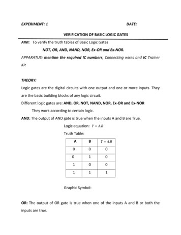
Transcription
July 10, 2002 12:54vra23151 fmtSheet number 1 Page number iblackFundamentalsofDigital Logic with Verilog DesignStephen Brown and Zvonko VranesicDepartment of Electrical and Computer EngineeringUniversity of TorontoBoston Burr Ridge, IL Dubuque, IA Madison, WI New York San Francisco St. LouisBangkok Bogotá Caracas Kuala Lumpur Lisbon London Madrid Mexico CityMilan Montreal New Delhi Santiago Seoul Singapore Sydney Taipei Toronto
July 15, 2002 09:50vra23151 copSheet number 1 Page number iiblackMcGraw-Hill Higher EducationA Division of The McGraw-Hill CompaniesFUNDAMENTALS OF DIGITAL LOGIC WITH VERILOG DESIGNPublished by McGraw-Hill, a business unit of The McGraw-Hill Companies, Inc., 1221 Avenue of the Americas,New York, NY 10020. Copyright 2003 by The McGraw-Hill Companies, Inc. All rights reserved. No part ofthis publication may be reproduced or distributed in any form or by any means, or stored in a database orretrieval system, without the prior written consent of The McGraw-Hill Companies, Inc., including, but notlimited to, in any network or other electronic storage or transmission, or broadcast for distance learning.Some ancillaries, including electronic and print components, may not be available to customers outside theUnited States.This book is printed on acid-free paper.International 1 2 3 4 5 6 7 8 9 0 QPF/QPF 0 9 8 7 6 5 4 3 2Domestic1 2 3 4 5 6 7 8 9 0 QPF/QPF 0 9 8 7 6 5 4 3 2ISBN 0-07-282315-1ISBN 0-07-121322-8 (ISE)Publisher: Elizabeth A. JonesSenior sponsoring editor: Carlise PaulsonAdministrative assistant: Michaela M. GrahamExecutive marketing manager: John WannemacherSenior project manager: Jill R. PeterProduction supervisor: Kara KudronowiczLead media project manager: Judi DavidSenior media technology producer: Phillip MeekCoordinator of freelance design: Michelle D. WhitakerCover designer: Rokusek DesignCover image: Stephen Brown and Zvonko VranesicSenior photo research coordinator: Lori HancockCompositor: Techsetters, Inc.Typeface: 10/12 Times RomanPrinter: Quebecor World Fairfield, PALibrary of Congress Cataloging-in-Publication DataBrown, Stephen D.Fundamentals of digital logic with Verilog design / Stephen D. Brown, Zvonko G. Vranesic.—1st ed.p. cm. (McGraw-Hill Series in electrical and computer engineering)Includes index.ISBN 0-07-282315-11. Logic circuits—Design and construction—Data processing. 2. Verilog (Computer hardwaredescription language). 3. Computer-aided design. I. Vranesic, Zvonko G. II. Title. III. Series.TK7868.L6 B76 2003621.39 2—dc212002071439CIPINTERNATIONAL EDITION ISBN 0-07-121322-8Copyright 2003. Exclusive rights by The McGraw-Hill Companies, Inc., for manufacture and export. Thisbook cannot be re-exported from the country to which is is sold by McGraw-Hill. The International Edition isnot available in North America.www.mhhe.com
June 14, 2002 09:52vra23151 dedSheet number 1 Page number iiiTo Susan and Anneblack
June 20, 2002 09:49vra23151 ataSheet number 1 Page number vblackAbout the AuthorsStephen Brown received his B.A.Sc. degree in Electrical Engineering from the Universityof New Brunswick, Canada, and the M.A.Sc. and Ph.D. degrees in Electrical Engineeringfrom the University of Toronto. He joined the University of Toronto faculty in 1992, wherehe is now an Associate Professor in the Department of Electrical & Computer Engineering.He is also Director of Software Development at the Altera Toronto Technology Center.His research interests include field-programmable VLSI technology and computerarchitecture. He won the Canadian Natural Sciences and Engineering Research Council’s1992 Doctoral Prize for the best Ph.D. thesis in Canada.He has won four awards for excellence in teaching electrical engineering, computerengineering, and computer science courses. He is a coauthor of two other books: Fundamentals of Digital Logic with VHDL Design and Field-Programmable Gate Arrays.Zvonko Vranesic received his B.A.Sc., M.A.Sc., and Ph.D. degrees, all in Electrical Engineering, from the University of Toronto. From 1963–1965, he worked as a design engineerwith the Northern Electric Co. Ltd. in Bramalea, Ontario. In 1968 he joined the Universityof Toronto, where he is now a Professor in the Departments of Electrical & Computer Engineering and Computer Science. During the 1978–79 academic year, he was a Senior Visitorat the University of Cambridge, England, and during 1984–85 he was at the University ofParis, 6. From 1995 to 2000 he served as Chair of the Division of Engineering Science atthe University of Toronto. He is also involved in research and development at the AlteraToronto Technology Center.His current research interests include computer architecture, field-programmable VLSItechnology, and multiple-valued logic systems.He is a coauthor of four other books: Computer Organization, 5th ed.; Fundamentalsof Digital Logic with VHDL Design; Microcomputer Structures; and Field-ProgrammableGate Arrays. In 1990, he received the Wighton Fellowship for “innovative and distinctivecontributions to undergraduate laboratory instruction.”He has represented Canada in numerous chess competitions. He holds the title ofInternational Master.v
July 10, 2002 15:44vra23151 serSheet number 1 Page number viblackMcGraw-Hill Series in Electrical and Computer EngineeringBrown, Vranesic: Fundamentals of Digital Logic with VHDL DesignGivone: Digital Principles and DesignHam, Kostanic: Principles of Neurocomputing for Science and EngineeringHamacher, Vranesic, and Zaky: Computer OrganizationHayes: Computer Architecture and OrganizationHwang: Advanced Computer Architecture: Parallelism, Scalability, ProgrammabilityHwang: Scalable Parallel Computing: Technology, Architecture, ProgrammingLeon-Garcia, Widjaja: Communication NetworksMarcovitz: Inroduction to Logic DesignNavabi: VHDL: Analysis and Modeling of Digital SystemsPatt, Patel: Introduction to Computing Systems: From Bits & Gates to C & BeyondSchalkoff: Artificial Neural NetworksShen, Lipasti: Modern Processor Designvi
July 10, 2002 14:23vra23151 fwdSheet number 1 Page number viiblackForewordChess is a game that provides a splendid vehicle for displaying human intelligence in acompetitive environment. During the past 30 years, it has also served as a platform fordetermining the extent to which machines can emulate intelligent behavior. Many chessprograms are available for today’s computers. Chess machines, comprising a computer anda chess-playing program, are now capable of defeating even the strongest human players.The ultimate challenge took place in 1997, when IBM’s Deep Blue chess machinedefeated the World Champion Garry Kasparov in a six-game match. The essence of thismachine are logic circuits, algorithms, and software—coupled with people who know howto use these resources. Although all of these factors are crucial, the greatest leap forward,in terms of chess-playing strength, was made when extremely powerful logic circuits weredeveloped. Most of these circuits are used in general purpose computers, but some arespecialized for the chess-playing application. A key reason why the Deep Blue machine isso strong is that it can evaluate about 200 million chess position in one second.This textbook deals with logic circuits and explains how they are designed. We haveincluded in the book the moves from the decisive sixth game of the 1997 match to remindthe reader of the incredible possibilities that are attainable with well-designed logic circuits.Deep Blue played with the white pieces.vii
July 10, 2002 14:25vra23151 prSheet number 1 Page number viiiblackPrefaceThis book is intended for an introductory course in digital logic design, which is a basiccourse in most electrical and computer engineering programs. A successful designer ofdigital logic circuits needs a good understanding of basic concepts and a firm grasp ofcomputer-aided design (CAD) tools. The purpose of our book is to provide the desirablebalance between teaching the basic concepts and practical application through CAD tools.To facilitate the learning process, the necessary CAD software is included as an integralpart of the book package.A serious drawback of many books on digital logic design is that they cover too muchmaterial. A book that covers a large number of topics is not easy to use in a classroom,particularly if the topics are not covered in sufficient depth. Also, in their desire to providea vast amount of practical advice, the authors often make the text difficult to follow by thestudents who are still struggling with the fundamental concepts. Our aim is to avoid bothof these problems.The main goals of the book are (1) to teach students the fundamental concepts inclassical manual digital design and (2) illustrate clearly the way in which digital circuitsare designed today, using CAD tools. Even though modern designers no longer use manualtechniques, except in rare circumstances, our motivation for teaching such techniques isto give students an intuitive feeling for how digital circuits operate. Also, the manualtechniques provide an illustration of the types of manipulations performed by CAD tools,giving students an appreciation of the benefits provided by design automation. Throughoutthe book, basic concepts are introduced by way of examples that involve simple circuitdesigns, which we perform using both manual techniques and modern CAD-tool-basedmethods. Having established the basic concepts, more complex examples are then provided,using the CAD tools. Thus our emphasis is on modern design methodology to illustratehow digital design is carried out in practice today.Technology and CAD SupportThe book discusses modern digital circuit implementation technologies. We briefly discussSSI, as well as semi-custom and full-custom technologies. However, the emphasis is onprogrammable logic devices (PLDs). This is the most appropriate technology for use in atextbook for two reasons. First, PLDs are widely used in practice and are suitable for almostall types of digital circuit designs. In fact, students are more likely to be involved in PLDbased designs at some point in their careers than in any other technology. Second, circuitsare implemented in PLDs by end-user programming. Therefore, students can be providedwith an opportunity, in a laboratory setting, to implement the book’s design examples inactual chips. Students can also simulate the behavior of their designed circuits on their owncomputers. We use the two most popular types of PLDs for targeting of designs: complexprogrammable logic devices (CPLDs) and field-programmable gate arrays (FPGAs).viii
July 10, 2002 14:25vra23151 prSheet number 2 Page number ixblackPrefaceOur CAD support is based on Altera MAX plusII software. MAX plusII providesautomatic mapping of a design into Altera CPLDs and FPGAs, which are among the mostwidely used PLDs in the industry. The features of MAX plusII that are particularly attractive for our purposes are: It is a commercial product. The version included with the book supports all majorfeatures of the product. Students will be able to easily enter a design into the CADsystem, compile the design into a selected device (the choice of device can be changedat any time and the design retargeted to a different device), simulate the functionalityand detailed timing of the resulting circuit, and if laboratory facilities are provided atthe student’s school, implement the designs in actual devices. It provides for design entry using both hardware description languages (HDLs) andschematic capture. In the book, we provide examples of design using schematic capture,but we emphasize the HDL-based design because it is the most efficient design methodto use in practice. We describe in detail the IEEE Standard Verilog language and useit extensively in examples. The CAD system included with the book has a Verilogcompiler, which allows the student to automatically create circuits from the Verilogcode and implement these circuits in real chips. It can automatically target a design to various types of devices. This feature allows usto illustrate the ways in which the architecture of the target device affects a designer’scircuit. It can be used on most types of popular computers. We expect that most students willuse the version of the software that runs on IBM-compatible computers (running anyversion of Microsoft windows), which is provided with the book. However, throughAltera’s university program the software is also available for other machines, such asSUN or HP workstations.A MAX plusII CD-ROM is included with each copy of the book. Use of the softwareis fully integrated into the book so that students can try, firsthand, all design examples. Toteach the students how to use this software, the book includes three, progressively advanced,hands-on tutorials.Scope of the BookChapter 1 provides a general introduction to the process of designing digital systems. Itdiscusses the key steps in the design process and explains how CAD tools can be used toautomate many of the required tasks.Chapter 2 introduces the basic aspects of logic circuits. It shows how Boolean algebrais used to represent such circuits. It also gives the reader a first glimpse at Verilog, as anexample of a hardware description language that may be used to specify the logic circuits.The electronic aspects of digital circuits are presented in Chapter 3. This chapter showshow the basic gates are built using transistors and presents various factors that affect circuitperformance. The emphasis is on the latest technologies, with particular focus on CMOStechnology and programmable logic devices.Chapter 4 deals with the synthesis of combinational circuits. It covers all aspects ofthe synthesis process, starting with an initial design and performing the optimization stepsneeded to generate a desired final circuit. It shows how CAD tools are used for this purpose.ix
July 10, 2002 14:25xvra23151 prSheet number 3 Page number xblackPrefaceChapter 5 concentrates on circuits that perform arithmetic operations. It begins witha discussion of how numbers are represented in digital systems and then shows how suchnumbers can be manipulated using logic circuits. This chapter illustrates how Verilog canbe used to specify the desired functionality and how CAD tools provide a mechanism fordeveloping the required circuits. We chose to introduce the number representations at thispoint, rather than in the very beginning of the book, to make the discussion more meaningful and interesting, because we can immediately provide examples of how numericalinformation may be processed by actual circuits.Chapter 6 presents combinational circuits that are used as building blocks. It includesthe encoder, decoder, and multiplexer circuits. These circuits are very convenient forillustrating the application of many Verilog constructs, giving the reader an opportunity todiscover more advanced features of Verilog.Storage elements are introduced in Chapter 7. The use of flip-flops to realize regularstructures, such as shift registers and counters, is discussed. Verilog-specified designs ofthese structures are included.Chapter 8 gives a detailed presentation of synchronous sequential circuits (finite statemachines). It explains the behavior of these circuits and develops practical design techniques for both manual and automated design.Asynchronous sequential circuits are discussed in Chapter 9. While this treatment isnot exhaustive, it provides a good indication of the main characteristics of such circuits.Even though the asynchronous circuits are not used extensively in practice, they should bestudied because they provide an excellent vehicle for gaining a deeper understanding ofthe operation of digital circuits in general. They illustrate the consequences of propagationdelays and race conditions that may be inherent in the structure of a circuit.Chapter 10 is a discussion of a number of practical issues that arise in the design of realsystems. It highlights problems often encountered in practice and indicates how they canbe overcome. Examples of larger circuits illustrate a hierarchical approach in designingdigital systems. Complete Verilog code for these circuits is presented.Chapter 11 introduces the topic of testing. A designer of logic circuits has to be awareof the need to test circuits and should be conversant with at least the most basic aspects oftesting.Appendix A provides a complete summary of Verilog features. Although use of Verilogis integrated throughout the book, this appendix provides a convenient reference that thereader can consult from time to time when writing Verilog code.Appendices B, C, and D contain a sequence of tutorials on the MAX plusII CAD tools.This material is suitable for self-study; it shows the student in a step-by-step manner howto use the CAD software provided with the book.Appendix E gives detailed information about the devices used in illustrative examples.It also includes a brief discussion of TTL technology.What Can Be Covered in a CourseAll the material in the book can be covered in 2 one-quarter courses. A good coverageof the most important material can be achieved in a single one-semester, or even a onequarter, course. This is possible only if the instructor does not spend too much time teachingthe intricacies of Verilog and CAD tools. To make this approach possible, we organized
July 10, 2002 14:25vra23151 prSheet number 4 Page number xiblackPrefacethe Verilog material in a modular style that is conducive to self-study. Our experience inteaching different classes of students at the University of Toronto shows that the instructormay spend only 2 to 3 lecture hours on Verilog, concentrating mostly on the specificationof sequential circuits. The Verilog examples given in the book are largely self-explanatory,and students can understand them easily. Moreover, the instructor need not teach how to usethe CAD tools, because the MAX plusII tutorials in Appendices B, C, and D are suitablefor self-study.The book is also suitable for a course in logic design that does not include exposure toVerilog. However, some knowledge of Verilog, even at a rudimentary level, is beneficialto the students, and it is a great preparation for a job as a design engineer.One-Semester CourseA natural starting point for formal lectures is Chapter 2. The material in Chapter 1 isa general introduction that serves as a motivation for why logic circuits are important andinteresting; students can read and understand this material easily.The following material should be covered in lectures: Chapter 2—all sections. Chapter 3—sections 3.1 to 3.7. Also, it is useful to cover sections 3.8 and 3.9 if thestudents have some basic knowledge of electrical circuits. Chapter 4—sections 4.1 to 4.7 and section 4.12.Chapter 5—sections 5.1 to 5.5. Chapter 6—all sections.Chapter 7—all sections. Chapter 8—sections 8.1 to 8.9.If time permits, it would also be very useful to cover sections 9.1 to 9.3 and section 9.6 inChapter 9, as well as one or two examples in Chapter 10.One-Quarter CourseIn a one-quarter course the following material can be covered: Chapter 2—all sections. Chapter 3—sections 3.1 to 3.3.Chapter 4—sections 4.1 to 4.5 and section 4.12.Chapter 5—sections 5.1 to 5.3 and section 5.5. Chapter 6—all sections.Chapter 7—sections 7.1 to 7.10 and section 7.13.Chapter 8—Sections 8.1 to 8.5.A More Traditional ApproachThe material in Chapters 2 and 4 introduces Boolean algebra, combinational logic circuits,and basic minimization techniques. Chapter 2 provides initial exposure to these topics usingonlyAND, OR, NOT, NAND, and NOR gates. Then Chapter 3 discusses the implementationtechnology details, before proceeding with the synthesis techniques and other types of gatesxi
July 10, 2002 14:25xiivra23151 prSheet number 5 Page number xiiblackPrefacein Chapter 4. The material in Chapter 4 is appreciated better if students understand thetechnological reasons for the existence of NAND, NOR, and XOR gates, and the variousprogrammable logic devices.An instructor who favors a more traditional approach may cover Chapters 2 and 4 insuccession. To understand the use of NAND, NOR, and XOR gates, it is necessary onlythat the instructor provide a functional definition of these gates.VerilogVerilog is a complex language, which some instructors feel is too hard for beginning studentsto grasp. We fully appreciate this issue and have attempted to solve it. It is not necessaryto introduce the entire Verilog language. In the book we present the important Verilogconstructs that are useful for the design and synthesis of logic circuits. Many other languageconstructs, such as those that have meaning only when using the language for simulationpurposes, are omitted. The Verilog material is introduced gradually, with more advancedfeatures being presented only at points where their use can be demonstrated in the designof relevant circuits.The book includes more than 140 examples of Verilog code. These examples illustratehow Verilog is used to describe a wide range of logic circuits, from those that contain onlya few gates to those that represent digital systems such as a simple processor.Homework ProblemsMore than 400 homework problems are provided in the book. Solutions to these problemsare available to instructors in the Solutions Manual that accompanies the book.LaboratoryThe book can be used for a course that does not include laboratory exercises, in which casestudents can get useful practical experience by simulating the operation of their designedcircuits by using the CAD tools provided with the book. If there is an accompanying laboratory, then a number of design examples in the book are suitable for laboratory experiments.Additional experiments are available on the authors’ website.AcknowledgmentsWe wish to express our thanks to the people who have helped during the preparation of thebook. Kelly Chan helped with the technical preparation of the manuscript. Dan Vranesicproduced a substantial amount of artwork. He and Deshanand Singh also helped with thepreparation of the solutions manual. The reviewers, William Barnes, New Jersey Instituteof Technology; James Clark, McGill University; Stephen DeWeerth, Georgia Institute ofTechnology; Clay Gloster, Jr., North Carolina State University (Raleigh); Carl Hamacher,Queen’s University; Wei-Ming Lin, University of Texas (Austin); Wayne Loucks, University of Waterloo; Chris Myers, University of Utah; James Palmer, Rochester Institute of
July 10, 2002 14:25vra23151 prSheet number 6 Page number xiiiblackPrefaceTechnology; Gandhi Puvvada, University of Southern California; Teodoro Robles, Milwaukee School of Engineering; Tatyana Roziner, Boston University; Rob Rutenbar, CarnegieMellon University; Charles Silio, Jr., University of Maryland; Scott Smith, University ofMissouri (Rolla); Arun Somani, Iowa State University; and Zeljko Zilic, McGill Universityprovided constructive criticism and made numerous suggestions for improvements. Weare grateful to the Altera Corporation for providing the MAX plusII CAD system. Thesupport of McGraw-Hill people has been exemplary. We truly appreciate the help of Kelley Butcher, Catherine Fields Shultz, Michaela Graham, Betsy Jones, Kara Kudronowicz,Carlise Paulson, Jill Peter, John Wannemacher, and Michelle Whitaker.Stephen Brown and Zvonko Vranesicxiii
July 2, 2002 09:33vra23151 tcSheet number 1 Page number xvblackContentsChapter2.10 Introduction to Verilog1Design Concepts1.1Digital Hardware1.1.11.1.21.1.31.21.3122.10.2Standard Chips 4Programmable Logic DevicesCustom-Designed Chips 5The Design Process 6Design of Digital Hardware1.3.11.3.21.41.52.10.12.11 Concluding RemarksProblems 61References 658Basic Design Loop 8Design of a Digital Hardware UnitLogic Circuit Design in This BookTheory and Practice 14References 15Chapter2.10.34Chapter911Introduction to LogicCircuits 172.5Boolean 63.7Sum-of-Products and Product-of-SumsForms 37Three-Way Light ControlMultiplexer Circuit 45Design Entry 48Synthesis 51Functional SimulationSummary eries Standard Chips8387Programmable Logic Array (PLA) 87Programmable Array Logic (PAL) 90Programming of PLAs and PALs 92Complex Programmable Logic Devices(CPLDs) 94Field-Programmable Gate Arrays 98Using CAD Tools to ImplementCircuits in CPLDs and FPGAs 102Custom Chips, Standard Cells, and GateArrays 103Practical Aspects 1063.8.144Speed of Logic Gate CircuitsProgrammable Logic Devices3.6.13.6.23.6.33.6.4The Venn Diagram 30Notation and Terminology 34Precedence of Operations 34Introduction to CAD Tools2.9.12.9.22.9.32.9.4Negative Logic SystemStandard Chips 8327NAND and NOR Logic NetworksDesign Examples 442.8.12.8.23.43.53.6Synthesis Using AND, OR, and NOTGates 352.6.1Transistor Switches 69NMOS Logic Gates 71CMOS Logic Gates 743.5.1Analysis of a Logic Network33.13.23.33.3.1Variables and Functions 18Inversion 21Truth Tables 22Logic Gates and Networks 2360Implementation Technology22.12.22.32.454Structural Specification of LogicCircuits 55Behavioral Specification of LogicCirucits 58How Not to Write Verilog Code 60MOSFET Fabrication andBehavior 106MOSFET On-Resistance 110Voltage Levels in Logic Gates 111Noise Margin 113Dynamic Operation of LogicGates 114Power Dissipation in LogicGates 117
July 2, 2002 09:33vra23151 tcxvi3.8.8Passing 1s and 0s Through TransistorSwitches 118Fan-in and Fan-out in LogicGates 120Transmission Gates3.9.13.9.2126Exclusive-OR Gates 127Multiplexer Circuit 1283.10 Implementation Details for SPLDs, CPLDs,and FPGAs 1293.10.1Implementation in FPGAs3.11 Concluding RemarksProblems 138References alysis of Multilevel CircuitsCubical Representation 1894.9A Tabular Method for Minimization4.8.14.9.14.9.24.9.3Cubes and mination of Essential PrimeImplicants 204Complete Procedure for Findinga Minimal Cover 2064.11 Practical Considerations4.12 CAD Tools 2094.12.14.12.24.12.35.5.2Generation of Prime Implicants 193Determination of a Minimum Cover 195Summary of the Tabular Method 2005.5.7208Logic Synthesis and OptimizationPhysical Design 211Timing Simulation 2135.6210240255Carry-Lookahead Adder255Design of Arithmetic Circuits Using CADTools 2625.5.1189234Negative Numbers 240Addition and Subtraction 224Adder and Subtractor Unit 248Radix-Complement Schemes 249Arithmetic Overflow 253Performance Issues 254Fast Adders5.4.15.54.10 A Cubical Technique for Minimization4.10.15.4230Decomposed Full-Adder 238Ripple-Carry Adder 239Design Example 240Signed Numbers5.3.15.3.25.3.35.3.45.3.55.3.6Factoring 172Functional Decomposition 175Multilevel NAND and NORCircuits 181229Unsigned Integers 230Conversion Between Decimaland Binary Systems 231Octal and HexadecimalRepresentations 232Addition of Unsigned Numbers5.2.15.2.25.2.3Minimization of Product-of-SumsForms 164Incompletely Specified Functions 166Multiple-Output Circuits 167Multilevel Synthesis 1715Positional Number Representation5.1.15.1.2Terminology 159Minimization Procedure220Number Representationand Arithmetic Circuits4Karnaugh Map 150Strategy for MinimizationSummary of Design Flow 213Examples of Circuits Synthesizedfrom Verilog Code 2164.13 Concluding RemarksProblems 221References 226Optimized Implementationof Logic Functions 1494.14.2blackContents3.8.73.9Sheet number 2 Page number xviDesign of Arithmetic Circuits UsingSchematic Capture 262Design of Arithmetic Circuits UsingVerilog 265Using Vectored Signals 268Using a Generic Specification 269Nets and Variables in Verilog 270Arithmetic AssignmentStatements 271Representation of Numbers in VerilogCode 275Multiplication5.6.15.6.2277Array Multiplier for UnsignedNumbers 279Multiplication of Signed Numbers279
July 2, 2002 09:33vra23151 tcSheet number 3 Page number xviiblackxviiContents5.7Other Number Representations5.7.15.7.25.7.35.82827.4Fixed-Point Numbers 282Floating-Point Numbers 282Binary-Coded-DecimalRepresentation 284ASCII Character CodeProblems 291References ers6.1.16.1.26.2Decoders6.2.16.36.46.56.6316Binary Encoders 316Priority Encoders ops, Registers,Counters, and a SimpleProcessor 3497.3Gated D Latch7.2.17.3.17.13.3BCD Counter 382Ring Counter 383Johnson Counter 384Remarks on Counter Design385Including Storage Elementsin Schematics 385Using Verilog Constructs for StorageElements 388Blocking and Non-blockingAssignments 390Non-blocking Assignments forCombinational Circuits 394Flip-Flops with Clear Capability 395Including Registers and Countersin Schematics 396Using Library Modules in VerilogCode 399Using Verilog Constructs for Registersand Counters 4007.14 Design ExamplesGated SR Latch with NAND Gates356Effects of Propagation DelaysAsynchronous Counters 371Synchronous Counters 374Counters with Parallel Load 3787.13 Using Registers and Counters with CADTools 3967.13.2Basic Latch 351Gated SR Latch 3533703717.10 Reset Synchronization 3787.11 Other Types of Counters 3827.12.177.17.23687.12 Using Storage Elements with CADTools 385The Conditional Operator 321The If-Else Statement 323The Case Statement 326The For Loop 331Verilog Operators 333The Generate Construct 338Tasks and Functions 339Concluding RemarksProblems 343References 3477.9.17.9.27.9.3367Shift Register 369Parallel-Access Shift RegisterCounters7.11.17.11.27.11.37.11.4314Code Converters 318Arithmetic Comparison Circuits 320Verilog for Combinational Circuits iplexersEncoders6.3.16.3.2298Synthesis of Logic Functions UsingMultiplexers 303Multiplexer Synthesis Using Shannon’sExpansion 304364Configurable Flip-FlopsJK Flip-Flop 367Summary of TerminologyRegisters 3687.8.17.8.27.9Master-Slave D Flip-Flop 359Edge-Triggered D Flip-Flop 360D Flip
This book is intended for an introductory course in digital logic design, which is a basic course in most electrical and computer engineering programs. A successful designer of digital logic circuits needs a good understanding of basic concepts and a firm grasp of computer-aided design (