Transcription
Gates and Logic:From switches to Transistors,Logic Gates and Logic CircuitsHakim WeatherspoonCS 3410, Spring 2013Computer ScienceCornell UniversitySee: P&H Appendix C.2 and C.3 (Also, see C.0 and C.1)
iClickerLab0 wasa) Too easyb) Too hardc) Just rightd) Have not done lab yet
Goals for TodayFrom Switches to Logic Gates to Logic CircuitsLogic Gates From switches Truth TablesLogic Circuits Identity Laws From Truth Tables to Circuits (Sum of Products)Logic Circuit Minimization Algebraic Manipulations Truth Tables (Karnaugh Maps)Transistors (electronic switch)
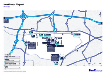
A switch Acts as a conductor orinsulator Can be used to buildamazing things The Bombe used to break the GermanEnigma machine during World War II
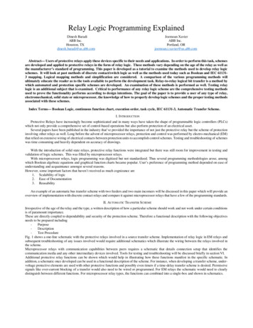
Basic Building Blocks: Switches to Logic Gates Truth TableA-B htLight
Basic Building Blocks: Switches to Logic GatesEither (OR) Truth TableA-BABLightOFFOFFOFFOFFONONONOFFONONONONBoth (AND) AB-ABLightOFFOFFOFFOFFONOFFONOFFOFFONONON
Basic Building Blocks: Switches to Logic GatesEither (OR)Truth TableA-ORBABLightOFFOFFOFFOFFONONONOFFONONONONBoth (AND)A-ANDBABLightOFFOFFOFFOFFONOFFONOFFOFFONONON
Basic Building Blocks: Switches to Logic GatesEither (OR)Truth TableA-ORBABLight000011101111Both (AND)A-ANDBABLight0000101001110 OFF1 ON
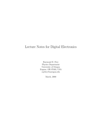
Basic Building Blocks: Switches to Logic GatesAORBGeorge Boole,(1815-1864)ADid you know?BGeorge Boole Inventor of the ideaof logic gates. He was born inLincoln, England and he was the sonof a shoemaker in a low class family.AND
TakeawayBinary (two symbols: true and false) is the basis ofLogic Design
Building Functions: Logic GatesNOT:AOutInA B OutAND: ABOR:ABLogic Gates0 000 101 001 11A B Out0 000 111 011 11 digital circuit that either allows a signal to pass through it or not. Used to build logic functions There are seven basic logic gates:AND, OR, NOT,NAND (not AND), NOR (not OR), XOR, and XNOR (not XOR) [later]
Building Functions: Logic GatesNOT:AInOut0110A B OutAND: ABOR:ABLogic Gates0 000 101 001 11A B Out0 000 111 011 11 digital circuit that either allows a signal to pass through it or not. Used to build logic functions There are seven basic logic gates:AND, OR, NOT,NAND (not AND), NOR (not OR), XOR, and XNOR (not XOR) [later]
Building Functions: Logic GatesNOT:AInOut0110A B OutAND: ABOR:ABLogic Gates0 000 101 001 11A B Out0 000 111 01 1A B OutNAND:ABNOR:A0 010 111 011 10A B Out0 010 1011 0011 10B digital circuit that either allows a signal to pass through it or not. Used to build logic functions There are seven basic logic gates:AND, OR, NOT,NAND (not AND), NOR (not OR), XOR, and XNOR (not XOR) [later]
Activity#1.A: Logic GatesFill in the truth table, given the following LogicCircuit made from Logic AND, OR, and NOT gates.What does the logic circuit do?abOutabOut
Activity#1.A: Logic GatesXOR: out 1 if a or b is 1, but not both;out 0 otherwise.out 1, only if a 1 AND b 0OR a 0 AND b 1abOut000011101110abOut
Activity#1.A: Logic GatesXOR: out 1 if a or b is 1, but not both;out 0 otherwise.out 1, only if a 1 AND b 0OR a 0 AND b 1abOut000011101110abOut
Activity#1: Logic GatesFill in the truth table, given the following LogicCircuit made from Logic AND, OR, and NOT gates.What does the logic circuit do?abd000001010011100101110111OutadbOut
Activity#1: Logic GatesMultiplexor: select (d) between two inputs (a and b)and set one as the output (out)?out a, if d 0out b, if d 1abdOut00000010010001111001101011011111adbOut
Goals for TodayFrom Switches to Logic Gates to Logic CircuitsLogic Gates From switches Truth TablesLogic Circuits Identity Laws From Truth Tables to Circuits (Sum of Products)Logic Circuit Minimization Algebraic Manipulations Truth Tables (Karnaugh Maps)Transistors (electronic switch)
Next GoalGiven a Logic function, create a Logic Circuit thatimplements the Logic Function and, with the minimum number of logic gatesFewer gates: A cheaper ( ) circuit!
Logic GatesNOT:AInOut0110A B OutAND:ABOR:ABXOR:0 000 101 001 11A B Out0 000 111 011 11A B OutALBogic Equations0 000 111 011 1 00Constants: true 1, falseVariables: a, b, out, Operators (above): AND, OR, NOT, etc.
Logic GatesNOT:AInOut0110A B OutAND:ABOR:ABXOR:0 000 101 001 11A B Out0 000 111 01 1A B OutNAND:ABNOR:A10 111 011 10A B Out0 010 1011 0011 10BXNOR:A B OutALBogic Equations0 00 000 111 011 1 00Constants: true 1, falseVariables: a, b, out, Operators (above): AND, OR, NOT, etc.A B OutAB0 010 101 001 11
Logic EquationsNOT: out ā !a aAND: out a b a & b a bOR: out a b a b a bXOR: out a b ab ābLogic Equations Constants: true 1, false 0 Variables: a, b, out, Operators (above): AND, OR, NOT, etc.
Logic EquationsNOT: out ā !a aAND:NAND:OR:NOR:XOR:XNOR: out a b a & b a b out a b a b a b out a b ab ābLogic Equations out a b !(a & b) (a b) out a b !(a b) (a b) out a b ab ab Constants: true 1, false 0 Variables: a, b, out, Operators (above): AND, OR, NOT, . etc.
IdentitiesIdentities useful for manipulating logic equations– For optimization & ease of implementationa 0 a 1 a ā a 0 a 1 a ā
IdentitiesIdentities useful for manipulating logic equations– For optimization & ease of implementationa 0 aa 1 1a ā 1aba 0 0a 1 aa ā 0ab
IdentitiesIdentities useful for manipulating logic equations– For optimization & ease of implementation(a b) (a b) a ab a(b c) a(b c)
IdentitiesIdentities useful for manipulating logic equations– For optimization & ease of implementationA(a b) a b(a b) a ba ab aa(b c) ab aca(b c) a b cBAB ABAB
Activity #2: Identitiesa 0 a 1 a ā a0 a1 aā a110a0(a b) (a b) a ab a(b c) a(b c) Show that the Logic equationsbelow are equivalent.(a b)(a c) a bcaba baab aca bc(a b)(a c)
Activity #2: Identitiesa 0 a 1 a ā a0 a1 aā a110a0(a b) (a b) a ab a(b c) a(b c) Show that the Logic equationsbelow are equivalent.(a b)(a c) a bcaba baab aca bc(a b)(a c) aa ab ac bc a a(b c) bc a(1 (b c)) bc a bc
Logic Manipulation functions: gates truth tables equations Example: (a b)(a c) a bcabc000001010011100101110111
Logic Manipulation functions: gates truth tables equations Example: (a b)(a c) a bcabca ba 01111011101110111111111
TakeawayBinary (two symbols: true and false) is the basis ofLogic DesignMore than one Logic Circuit can implement sameLogic function. Use Algebra (Identities) or TruthTables to show equivalence.
Goals for TodayFrom Switches to Logic Gates to Logic CircuitsLogic Gates From switches Truth TablesLogic Circuits Identity Laws From Truth Tables to Circuits (Sum of Products)Logic Circuit Minimization Algebraic Manipulations Truth Tables (Karnaugh Maps)Transistors (electronic switch)
Next GoalHow to standardize minimizing logic circuits?
Logic MinimizationHow to implement a desired logic function?a00001111b00110011c out0 01 10 01 10 01 10 01 0
Logic MinimizationHow to implement a desired logic function?a00001111b00110011c out minterm 1) Write minterm’s0 0a b c 2) sum of products:1 1a b c OR of all minterms where out 10 0abc1 1abc0 0abc1 1abc0 0abc1 0abc
Logic MinimizationHow to implement a desired logic function?a00001111b00110011c out minterm 1) Write minterm’s0 0a b c 2) sum of products:1 1a b c OR of all minterms where out 10 0abc E.g. out abc abc abca1 1abcbc0 0abcout1 1abc0 0abc1 0abccorollary: any combinational circuit can be implemented intwo levels of logic (ignoring inverters)
Karnaugh MapsHow does one find the most efficient equation?– Manipulate algebraically until ?– Use Karnaugh maps (optimize visually)– Use a software optimizerFor large circuits– Decomposition & reuse of building blocks
Minimization with Karnaugh maps (1)Sum of minterms yieldsabcout00000011010001111001101111001110 out abc abc abc abc
Minimization with Karnaugh maps (2)Sum of minterms yieldscabcout00000011010001111001101111001110ab out abc abc abc abcKarnaugh maps identifywhich inputs are (ir)relevantto the output000111 100000111101
Minimization with Karnaugh maps (2)Sum of minterms yieldscabcout00000011010001111001101111001110ab out abc abc abc abcKarnaugh map minimization 000111100000111101 Cover all 1’sGroup adjacent blocks of 2n1’s that yield a rectangularshapeEncode the common featuresof the rectangle out ab ac
Karnaugh Minimization Tricks s can overlap out bc ac ababMinterms can span 2, 4, 8or more cells out c ab
Karnaugh Minimization Tricks s can overlap out bc ac ababMinterms can span 2, 4, 8or more cells out c ab
Karnaugh Minimization Tricks 1010000110000101001The map wraps around out bdabcd00 out bd
Karnaugh Minimization Tricks 1010000110000101001The map wraps around out bdabcd00 out bd
Karnaugh Minimization Tricks 00x010xx0110xx0101001abcd“Don’t care” values can beinterpreted individually inwhatever way is convenient assume all x’s 1 out d assume middle x’s 0 assume 4th column x 1 out bd
Karnaugh Minimization Tricks 00x010xx0110xx0101001abcd“Don’t care” values can beinterpreted individually inwhatever way is convenient assume all x’s 1 out d assume middle x’s 0 assume 4th column x 1 out bd
MultiplexerA multiplexer selectsbetween multiple inputsa out a, if d 0 out b, if d 1bdabd000001010011100101110111outBuild truth tableMinimize diagramDerive logic diagram
Multiplexer Implementationa Build a truth tablebout abd abd abd abddabdout00000010010001111001101011011111
Multiplexer Implementationa Build the Karnaugh 011110
Multiplexer Implementationa Build the Karnaugh 11100001110110
Multiplexer Implementationa Derive Minimal 1111ab000111100001110110 out ad bdaoutdb
TakeawayBinary (two symbols: true and false) is the basis ofLogic DesignMore than one Logic Circuit can implement sameLogic function. Use Algebra (Identities) or TruthTables to show equivalence.Any logic function can be implemented as “sum ofproducts”. Karnaugh Maps minimize number of gates.
Goals for TodayFrom Transistors to Gates to Logic CircuitsLogic Gates From transistors Truth TablesLogic Circuits Identity Laws From Truth Tables to Circuits (Sum of Products)Logic Circuit Minimization Algebraic Manipulations Truth Tables (Karnaugh Maps)Transistors (electronic switch)
Activity#1 How do we build electronic switches?Transistors: 6:10 minutes (watch from from 41s to 7:00) http://www.youtube.com/watch?v QO5FgM7MLGg Fill our Transistor Worksheet with info from Video
NMOS and PMOS Transistors NMOS TransistorPMOS TransistorVSVDVGVG VSVG 0 VVS 0 V Connect source to drainwhen gate 1 N-channelVGVG VSVG 0 VVD 0 VConnect source to drainwhen gate 0P-channel
NMOS and PMOS Transistors NMOS TransistorPMOS TransistorVSVDVGVG 1VG 0VS 0 V Connect source to drainwhen gate 1 N-channelVGVG 1VG 0VD 0 VConnect source to drainwhen gate 0P-channel
InverterVsupply (aka logic 1)in01out Function: NOT Called an inverter Symbol:inout(ground is logic 0)In01Out10Truth table Useful for taking theinverse of an input CMOS: complementary-symmetry metal–oxide–semiconductor
InverterVsupply (aka logic 1)in10out Function: NOT Called an inverter Symbol:inout(ground is logic 0)In01Out10Truth table Useful for taking theinverse of an input CMOS: complementary-symmetry metal–oxide–semiconductor
InverterVsupply (aka logic 1)out A 0 Out 1 A 1in Function: NOTOut 0 Called an inverter Symbol:inout(ground is logic 0)A01Out10Truth table Useful for taking theinverse of an input CMOS: complementary-symmetry metal–oxide–semiconductor
NAND GateVsupplyA1VsupplyB Function: NAND Symbol:10outB1AA01011B out01011110about
NOR Gate Function: NOR Symbol:VsupplyAB00a1outAA01010B out0 10 01 01 0B0bout
Building Functions (Revisited)NOT:AND:OR:NAND and NOR are universal Can implement any function with NAND or just NOR gates useful for manufacturing
Building Functions (Revisited)NOT:aAND:abOR:abNAND and NOR are universal Can implement any function with NAND or just NOR gates useful for manufacturing
Logic GatesOne can buy gates separately ex. 74xxx series ofintegrated circuits cost 1 per chip, mostlyfor packaging and testingCumbersome, but possible tobuild devices using gates puttogether manually
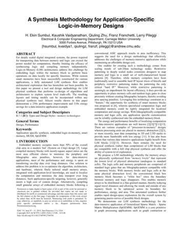
Then and Nowhttp://www.theregister.co.uk/2010/02/03/intel westmere ep preview/The first transistor An Intel Westmere on a workbench atAT&T Bell Labs in 1947 Bardeen, Brattain, and Shockley– 1.17 billion transistors– 240 square millimeters– Six processing cores
Big Picture: AbstractionHide complexity through simple abstractions Simplicity– Box diagram represents inputs and outputs Complexity– Hides underlying NMOS- and PMOS-transistors and atomicinteractionsVddaoutinoutbVssindoutadbout
SummaryMost modern devices are made from billions of on /offswitches called transistors We will build a processor in this course! Transistors made from semiconductor materials:– MOSFET – Metal Oxide Semiconductor Field Effect Transistor– NMOS, PMOS – Negative MOS and Positive MOS– CMOS – Complimentary MOS made from PMOS and NMOS transistors Transistors used to make logic gates and logic circuitsWe can now implement any logic circuit Can do it efficiently, using Karnaugh maps to find the minimalterms required Can use either NAND or NOR gates to implement the logiccircuit Can use P- and N-transistors to implement NAND or NOR gates
Logic Gates and Logic Circuits Hakim Weatherspoon CS 3410, Spring 2013 Computer Science Cornell University See: P&H Appendix C.2 and C.3 (Also, see C.0 and C.1) . There are seven basic logic gates: AND, OR, NOT, NAND (not AND), NOR (not OR), XOR, and XNOR (not XOR) [later