Transcription
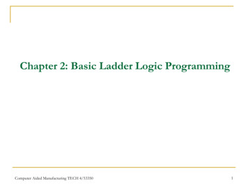
Relay Logic Programming ExplainedDinesh BaradiABB Inc.Houston, TXdinesh.baradi@us.abb.comJoemoan XavierABB Inc.Portland, ORjoemoan.i.xavier@us.abb.comAbstract— Users of protective relays apply these devices specific to their needs and applications. In order to perform this task, schemesare developed and applied to protective relays in the form of relay logic. These methods vary depending on the age of the relay as well asthe manufacturer’s standard of programming. This paper is developed as a tutorial to examine the methods used to develop relay logicschemes. It will look at past methods of discrete contact/switch logic as well as the methods used today such as Boolean and IEC 611313 mapping. Logical mapping methods and simplification are considered. A comparison of the various programming methods willultimately educate the reader as to the tools available to perform the development task. Relay-to-relay logical bit transfer is a method bywhich automated and protection specific schemes are developed. An examination of these methods is performed as well. Testing relaylogic is an additional subject that is examined. Critical to performance of any relay logic scheme are the comprehensive testing methodsused to prove the functionality performs according to design intentions. The goal of the paper is to provide a user of any type of relay,electromechanical, solid state or microprocessor, the knowledge of how to properly develop logic schemes and the proper testing methodsassociated with these schemes.Index Terms— Boolean Logic, continuous function chart, execution order, task cycle, IEC 61131-3, Automatic Transfer Scheme.I. I NTRODUCTIONProtective Relays have increasingly become sophisticated and in many ways have taken the shape of programmable logic controllers (PLCs)which not only provide a comprehensive set of control-based operations but also perform protection of an electrical asset.Several papers have been published in the industry that’ve provided the importance of not just the protective relay but the scheme of protectioninvolving other relays as well. Long before the advent of microprocessor relays, protection and control was performed by electro-mechanical (EM)that relied on extensive wiring of electrical contacts between protection units to accomplish control schemes. Testing and troubleshooting of schemeswas time consuming and heavily dependent on accuracy of drawings.With the introduction of solid state relays, protective relay functions were integrated but there was still room for improvement in testing andvalidation of logic schemes. This was filled by microprocessor relays.With microprocessor relays, logic programming was digitized but not standardized. Thus several programming methodologies arose, amongwhich Boolean algebraic equations and graphical function charts became popular. User’s preference of programming method depended on ease ofunderstanding and acquaintance amongst several reasons.However, some important factors that haven’t received as much cognizance are1. Scalability of logic2. Ease of Documentation3. ReusabilityAn example of an automatic bus transfer scheme with two feeders and two main incomers will be discussed in this paper which will provide anoverview of implementation with discrete contact relays and compare it against microprocessor relays that have a few of the programming standards.II. AUTOMATIC TRANSFER SCHEMEIrrespective of the age of the relay and the type, a written description of how a particular scheme should work and not work under certain conditionsis of paramount importance.These are directly coupled to dependability and security of the protection scheme. Therefore a functional description with the following objectivesneeds to be prepared includingPurposeDescriptionTest ProcedureFig. 1 shows a one-line schematic with the protective relays involved in a source transfer scheme. Implementation of relay logic in EM relays andsubsequent troubleshooting of any issues involved would require additional schematics which illustrate the wiring between the relays involved inthe scheme.Microprocessor relays with communication capabilities between peers requires a schematic that details connection setup that identifies thecommunication media and any other intermediary devices involved. Tools for testing and troubleshooting will be discussed briefly in section VI.Additional protective relay functions can be shown which would help in illustrating how these functions manifest in the specific schematic. Inaddition, a schematic once developed can be used in a functional description of the scheme. For instance, when developing a transfer scheme, undervoltage protective elements are used with other protective functions and possibly even timers if a time-delay transfer scheme is desired. Permissivesignals like over-current blocking of a transfer would also need to be wired or programmed. For EM relays the schematic would need to clearlydistinguish between different functions. For microprocessor relay types, the functions can combined into a single-box and shown in schematics.
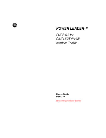
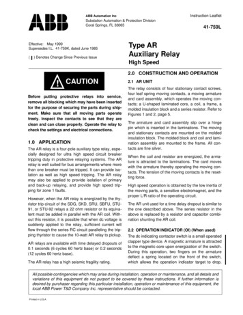
Fig. 1: One-line protection schematicLogic schematics can be drawn to illustrate how different protection elements are wired. In this example, a schematic when a Tie-relay closecircuit is energized is shown.Fig. 2: Close Circuit of Tie relayTrip and close circuits for both Mains and the Tie would also be illustrated and documented. Protection settings can also be documented toensure a single schematic provides reference during testing. The switches 43A (automatic) and manual transfer pushbuttons as well as lockoutrelays which provide permissive close are essential to the logic schematic as shown in Fig. 2. The principles used for simplifying and correlatinglogic design between electrical contacts and solid state logic units are shown in Fig. 3. It can be observed that physically Inverse AND, negationOR are functional equivalents of each other, however the solid state logic units for both have different representations. Furthermore, thenegation AND, Inverse OR are functional equivalents but the solid state representation differs.
Fig. 3: Logic gates and variationsIII. MICROPROCESSOR RELAY LOGICMicroprocessor relays with logic and communication capabilities can accomplish this type of scheme by using either hard-wired trip contactsor by using communication signals between each other to transfer statuses.By using the Boolean simplification, we can represent the logic in a microprocessor based relay in a few different ways. Textual based Booleanprogramming is one such way of representing logic. The logic in Fig. 2 can be interpreted and represented using Boolean symbols of ‘*’ for ANDgate and ‘ ’ for OR gate and ‘!’ for NOT.CLO TIE ((!43A MAN TRNSFR) * !86-F1* !86-B1*27-T1*27-M1*!52A-M2*!27-M2) ((!43A MAN TRNSFR) * !86-F2* !86-B2*27T2*27-M2*!52A-M1*!27-M1)Interpretation of the logic equation in such a form provides a challenge in developing logic that is intuitive and scalable. However it may bereused and replicated for a similar transfer scheme. Graphical programming of relay logic is intuitive and scalable compared to textual based formatand it is reusable. One such graphical format is shown in Fig. 4.Fig. 4: Signal mappingSignal mapping provides binary input, binary output and function mapping of relay connections.Fig. 4 translates some of the logic shown in Fig. 2. The ‘X’ in the mapping indicates a logical connection between input and the function. The‘I’ indicates an inverted (NOT) connection between the input and the function. This is equivalent to the ‘!’ Boolean connection. Such logical
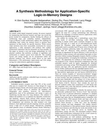
mapping is intuitive when logic is simple, however in terms of scalability and reusability it poses a challenge and it is not intuitive forprogramming sophisticated logic that is often required of microprocessor based relays. Therefore, a necessity arises for a logic format that canprovide ease of documentation, scalability in programming and at the same time be intuitive and easy to reuse. An existing format based on IEC61131-3 programming standard provides a solution that utilizes Continuous Function Chart (CFC) based convention. Some of the othergraphical IEC 61131-3 programming languages are Ladder diagram, Sequential function charts. Ladder diagram provides contacts, connectingwires and coils. Among the different programming formats of the IEC 61131-3 standard, Ladder diagram is the most similar to wiring ofcontacts as shown in Fig. 2. The only difference would be Ladder diagram is programmed from left to right and the wiring schematic isexecuted from top to bottom. CFC provides a digital worksheet based representation that not only provides relay users with the above benefitsbut also aids in troubleshooting and testing. It can also be used for providing an on-line view of the logical statuses of each element involved.Fig. 5 shows the digital worksheet based representation of schematic in Fig. 2.Fig. 5: Microprocessor relay logicFunction block based logic design can help create logic templates that can be used across different relays. In addition it would also facilitateusers in creating customized functions by using composite function blocks. The IEC 61131-3 programming standard incorporates and therebyenables logic designers to choose inputs and outputs of these composite blocks and the logic executed within them. Thus, a composite functionwhen required to be reused can be referenced.A. Comparison of LogicA requirement of comparing a logic that is downloaded in a relay and logic that is available in a file is useful in identifying if any modificationsand changes were made since relays are deployed into service. Textual representation of logic provides a very intuitive way to compare logic. CFCbased representation of logic can provide an even more intuitive method of comparison by checking the instance number of the function blocks andthe connections made to and from the specific function block.IV. ORDER OF EXECUTION, C YCLE TIMEIn newer generations of relays, one of the most important considerations is the order in which the logic is executed. For instance in Fig. 2, the orderof execution is from positive terminal to the negative terminal, it is analogous to the flow of current through the contacts of the EM, solid staterelays. If the concept of execution order were to be extended to DC logic schematic, then the contacts that are wired for any scheme would receiveprecedence starting from the positive terminal. For instance in Fig. 2, the Auto/ Manual selector switch (43A) receives the first precedence or isassigned execution order number 1 along with the Manual Transfer pushbutton, 86-F1 will receive order number 2 and 86-B1 will receive ordernumber 3 and so on.For EM relays, execution order may not be intuitive enough to comprehend because EM relays do not reset instantly. However, logic circuits thatbranch out can cause race conditions. In certain applications, time delay relays that provides a variable pickup are used. However there are certaincases where race conditions can occur between two completely different logic schematics. For example, a simultaneous transfer scheme where theopening of Main breaker and the closing of a Tie are initiated at the same instance as shown in Fig. 6.
Fig. 6: Simultaneous TransferOne can deduce that the execution order plays a significant role when designing logic in relays that provide multiple functions in a single relay. Formicroprocessor based relays, the cycle time is how frequently a function is performed or executed. This is either programmable or fixed based onthe relay. Both the execution order and cycle time play an important role in relay logic design and aid in detecting race conditions generated bypulses, latches and a combination of both. As various type of control schemes are integrated into modern microprocessor relays using flip-flops andtimers, embedding the calculated execution orders and cycle times into functions becomes critical to designing logic. For any given scheme thecycle time of a function may be fixed, however the execution order may vary depending on the connections made to the function. Note that in Fig.5, the execution order, cycle time and the instance number of the function are embedded in the bottom part of the function. Execution order andcycle time are highlighted in red in the format O: x, T: y where ‘x’ is a number and ‘y’ is time in milliseconds.A. Detecting anomalous execution order conditionsLogic programmers will innately grasp that the order should be increasing in numbers going from left to right. Validating this in complex designis time-consuming. As a result, the software used for programming would need to automatically compute the execution order of each functionblock used in the protection and control logic. This can be accomplished by tracing the logic from right to left and ensuring that the input of acertain function block with O: x is connected to the output of a function block with O: x-1 at the minimum, for a given cycle time. A recursiveloop can be programmed to detect for cases where this conditional statement doesn’t hold true for a given cycle time. Those connections can beflagged when logic is validated and compiled. There are multiple ways to correct these conditions automatically when logic is validated.Another way to detect for race conditions, is monitoring the sequence of events and co-relating them with a timestamp. This would requiredownloading logic to the microprocessor relay itself and testing the logic by simulating the actual conditions. Manually correcting theseconditions would involve identification of the signals that feed a control and extending the duration of these signals by at least one computationcycle to ensure an overlap occurs such the control output is initialized.B. Examples of execution order inconsistenciesA user implemented a Hot Line Tag Logic that should’ve worked in a manner that was described in red text of Fig. 7. However when Hot LineTag pushbutton was pressed on the relay locally to generate a 2.5 millisecond pulse, the Hot Line Tag condition never asserted. When reviewingthe logic the execution orders highlighted in red indicated that logic was not validated to account for execution order inconsistencies. Since thesoftware had the option to validate these inconsistencies the problem was resolved with ease.
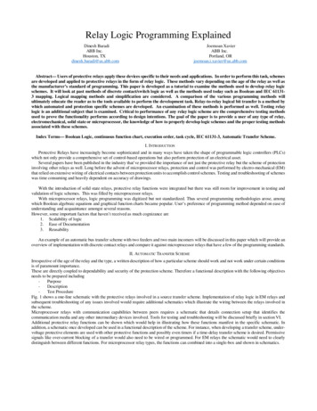
Fig. 7: Example - Hot Line Tag LogicC. Feedback LoopsFeedback loops are often used in microprocessor relays for different reasons. Some of them are to generate pulse signals of varying pulse widthto alarm on certain conditions, provide supervision between distributed control logic. If execution orders are not paid due diligence to when creatingfeedback loops then a function could be executed one cycle time after other logic functions are executed in the same loop. An example is shown inFig. 8 where asserting two inputs contacts X110-Input 1 and X110-Input 2 will cause X100-PO1 Output contact to close. Another condition causesthe same output contact to operate when another input contact X110-Input 3 will assert. In order to provide a supervision signal for the secondcondition, a feedback is created such that when the PO1 contact is already asserted then second condition will not operate the contact. While doingso the execution order for the feedback loop was not incrementing from left to right, this was corrected by setting a smaller execution number to theNOT gate.
Fig. 8: Example - feedback loopV. RELAY- TO-RELAY COMMUNICATIONTo reduce the complexity of wiring, relays with communication capabilities amongst themselves can exchange statuses like interlocking,blocking and control signals. The choice of transferring signals and controls between relays can be evaluated based on the nature of two categories:Ø Communication Topology – Point-to-Point (P2P) and Point-to-Multi-Point (P2MP)Ø Nature of communication protocol – Point-to-Point (P2P) and Point-to-Multi-Point (P2MP)A. P2P communication topologyP2P, bi-directional communication shown in Fig. 9 provides a means of exchanging binary statuses and controls between the Main #1 and Tierelay, Main #2 and Tie Relay. If statuses and controls need to be exchanged between the Main#1 and Main #2 relay, then the Tie relay wouldserve as an intermediate device. Disadvantage of this type of topology is that, it is not fault-tolerant as a single break in the link would mandatethe scheme being disabled. When any of the relays are being tested, statuses and control signals that are generated by the Device under test(DUT) would need to be tagged with a test flag that would inhibit any operations by the recipients. Recipient relays can be put into test mode aswell, this would be particularly useful for testing a scheme that involves communication based protection & control. The test bit implementationcan be programmed through contact inputs or it can be built-into the protocol itself. Latter not a scalable solution as wiring can be complex.B. P2MP communication topologyIf another bi-directional link is placed between the Main#1 and Main #2 as shown in Fig. 10, a P2MP topology can be created that couldaccommodate one fault in the system. For P2P communication protocols, each Main relay would need to send the signals from itself and the Tieand receive signals from the other Main and the Tie. Tie Relay would send and receive signals from both the main relays.A disadvantage with P2P protocols is that when large systems are to be designed, scalability becomes a challenge while guaranteeing delivery ofcommunication packets at minimal latency. If P2MP protocols are used then a larger degree of scalability can be achieved compared to P2Pprotocol without compromising on latency. Another choice would be to design a P2P communication topology shown in Fig. 11 using a logicprocessor – communication hub or device that can publish & subscribe either P2P messages or P2MP messages. However, this system lacksredundancy, hence a P2MP topology, shown in Fig. 12 provides redundancy and optimum system availability.Fig. 9: P2P topology -1
Fig. 10: P2MP topologyFig. 11: P2P topology – 2Fig. 12: P2MP topology -2The choice of communication protocol for designing a protection and control scheme mandates the relay logic be designed taking into accountthe nature of the protocol. Certain protocols like IEC 61850 GOOSE (Generic Object Oriented Substation Event) have provisions to incorporatethe quality of the signals that can be utilized by GOOSE recipients to validate the signals and the message. Therefore the communication itselfneeds to be tested with the system to ensure instability and undesired interplay with other functions are mitigated. An integrated test plan that
validates functions of the logic in a given relay in a given scheme is recommended. It is equivalent to testing the physical wiring that connects thecontacts shown in Fig. 2.C. Example of logic considerations in a communication oriented schemeAn automatic transfer scheme that used non-redundant communication between two Main relays and a Tie relay was developed. Based on thesequence of operations, it was desired to disable the transfer scheme when the communication messages are unreliable and also notify the operatorso that remedial action could be pursued. Logic was developed in all relays to incorporate this functionality by monitoring the validity of the signalsbeing received. As the engineering settings were being updated in a Main relay it was observed that the scheme was disabled which was expectedas the relay went through a soft reboot to apply the new settings. However when the update was finished, the scheme was still disabled. Upondiagnosing the logic starting from the Tie relay, it was observed that the TIE TRANSFER BLOCK, shown in Fig. 13 was asserted, which indicatedthe SR-1, Q1 output flip-flop never reset.Fig. 13: Example – transfer disableWhen the set (S1) & reset (R1) logic was traced back, it was observed that the ‘S1’ input consisted of multiple signals whose validity were beingsupervised as shown in Fig. 14. During the update, transfer was set to Auto mode which provided a possible explanation for the undesiredconsequence.Fig. 14: S1 logicThe Reset (R1) logic would be asserted by conditions indicated in Fig. 15. It was noticed that the same validity signals that set the SR-1, Q1 outputdidn’t reset the output.
Fig. 15: Tie - R1 logicIt was further observed that the Main relays were sending a Transfer reset signal to the Tie relay. Upon diagnosing the logic in the main incomers,it was noticed that the reset logic developed was the no different than the Tie.Fig. 16: Main 2 – R1 LogicAs a result of this, it was concluded that for a communication timeout the scheme would’ve been disabled and stayed in that mode even after thetimeout was rectified. Quality signals of all the received messages were aggregated into the reset logic, which would’ve mitigated this problemfrom occurring while the scheme was in operation. Three relays was required to have mutually inclusive control to unblock the Scheme thus, thelogic in the Main incomers was also corrected to encompass the required.VI. TESTING AND TROUBLESHOOTINGFrom the example in Section V.C, it can be concluded that an integrated test plan which addresses testing the scheme itself apart from theindividual components is a recommended approach.When testing EM and solid-state relay based schemes, existing system considerations and tools become more simplified. However the tools fordiagnosing why the test failed or passed are limited. Microprocessor based relays where communications are used for protection and control wouldmandate additional testing. A number of test plans can be incorporated with the aim of testing individual logic components as well the entire systemitself. An example of test scenarios is shown in Table 1. It must be noted that the testing methodology follows the pattern of logic execution.For EM and solid -State relays, one can develop a checklist to perform metering, protection, functional and control scheme relevant testing. Formicroprocessor relays a similar checklist can be developed. EM relays have flags that provide indication of breaker trip, whereas solid state relaystypically provide pickup and/or trip lights at the minimum to indicate a status, in addition to a testing pushbutton which would aid in functionaltesting of the contacts that validate the wiring. In microprocessor relays diagnostic information for testing a scenario(s) are all-embracing. Fromphasor diagrams, event records, disturbance records to even communication counters, a wide range of tools are available for validating and testing.One such tool that provides diagnosis of relaying logic is worth mentioning – a real-time logic monitoring tool which can be used to view howcertain conditions interplay on a real-time basis. An example of this is shown in Fig. 7.A. Communication testingSchemes that are developed using communication would mandate testing of communication links and also the communication equipment usingwhich protection and control traffic traverses through. While a simple test like removing communication cable from port of the relay may sufficefor testing the link, testing the equipment itself requires a communication schematic to identify the devices involved and knowledge of the P2P orP2MP topology being used.Table 1: Example test scenariosTEST#SCENARIO1Main#1 CloseMain#2 CloseTESTCONDITIONSimulate loss ofMain#1 byopening voltagetest switchEXPECTED RESULTMain#1 OpenTie Closes after Main#1 opens
Tie Open43A in closedAll lockouts areresetNOTE: Return system to normal operating conditionSimulate loss ofMain#1 by2Main#1 Closeopening voltagetest switchMain#2 CloseTie Open43A open, allother lockoutresetNOTE: Return system to normal operating conditionSimulate loss ofMain#1 by3Main#1 Closeopening voltagetest switchMain#2 CloseTie Open43A closed, 86F1 Lockoutrolled, all otherlockout resetNOTE: Return system to normal operating conditionMain#1 OpenTie shouldn't close after Main#1 opensMain#1 OpenTie shouldn't close after Main#1 opensVII. SUMMARYAs protective relays have evolved into controllers, tools for programming and troubleshooting have also advanced at the same pace. The conceptsof logic design in protective relays of today have many parallels one can draw from EM relay-based schemes. Solid state relays provided somebenefits when troubleshooting and testing. With advancements in software, troubleshooting sophisticated logic design became easier.REFERENCES1.2.3.4.5.Protective Relaying theory and application – Second Edition by Walt Elmore et al.The IEC 61131-3 Programming Languages Features for Industrial Control Systems – Ramakrishnan RamanathanIEC 61850 Edition 1 Part 7-4An Approach for Comparison of IEC 61131-3 Graphical Programs - Raoul Jetley, Anand Rath, Aparajithan V, KumarD, Vinu Prasad, Srini Ramaswamy, Industrial Software Systems, ABB Corporate Research, BangaloreInternational Institute of Information Technology, BangaloreLonWorks Network in Protection and Control Systems – User Manual and Technical Description
Fig. 5: Microprocessor relay logic Function block based logic design can help create logic templates that can be used across different relays. In addition it would also facilitate users in creating customized functions by using composite function blocks. The IEC 61131-3